Table of Contents
Advertisement
Quick Links
Advertisement
Table of Contents

Subscribe to Our Youtube Channel
Related Manuals for NTI ST-IPUSBD-L-DH


Summary of Contents for NTI ST-IPUSBD-L-DH
- Page 1 ST‐IPUSBD‐L/R‐DH Dual head DVI-I with USB KVM Extender over IP Setup Guide ...
-
Page 2: Table Of Contents
Introduction..................................1 Configuration ................................... 4 System ..................................4 Version Information..............................4 Update Firmware ..............................5 Utilities ................................... 6 Statistics..................................7 Network tab.................................. 8 IP Setup (TX/RX) ..............................8 Casting Mode (TX only) ............................8 Casting Mode (RX only)............................9 Jumbo Frame (TX/RX).............................. 9 Functions ................................... -
Page 3: Introduction
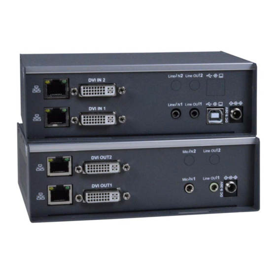
INTRODUCTION The XTENDEX® Dual Monitor DVI USB KVM Extender provides remote KVM (USB keyboard, USB mouse and two 1080p DVI monitors) access to a dual-head USB computer up to 472 feet (144 meters) away via two CAT6/6a/7 cables. Each KVM extender consists of a local unit that connects to a dual-head computer, and a remote unit that connects to two DVI monitors, 3.5mm stereo audio speakers and microphone, and up to four USB devices (keyboard, mouse, flash drive, HDD, or touchscreen display). - Page 4 Features and Functions Note: The Local and Remote units each contain 2 processors (A and B). The A processor supports DVI-I, USB, and 3.5mm Audio, while the B processor supports DVI-I only. The A is referred as “Main” and B is referred as “2nd“...
- Page 5 ST-USBD-R-DH Dual Head Receiver (Remote Unit) No. Connector Description 1A/1B Ethernet Main (1A) and 2 (1B) Gigabit Ethernet ports 2A/2B DVI‐I Out Main (2A) and 2 (2B) DVI‐I output ports 3 Mic. In Microphone Input, extend to the Line Out of Tx 4 Line Out 3.5mm Stereo Audio output port 5 DC Power input System power input, DC 12V. Green Blinking/Amber Off: System is starting up. Green On/Amber Off: System is ready, TX/RX not connected. Green On/AmberFast Blinking: Main/2 processors are 6A/6B Main/2 connecting. Green: System LED Green On/AmberSlow Blink: Main/2 processors are Amber: Link LED internally connected, TX/RX is externally connected, waiting for video input. ...
-
Page 6: Configuration
CONFIGURATION Use the Configuration Web page in the Local (TX) and Remote (RX) Units to configure them. There are Setup mode and Operation mode on the Configuration Web page. To enter TX/RX Operation mode Configuration Web page: 1. Directly connect the TX/RX to a PC LAN port. Set the PC IP address to 10.0.1.1, with Net Mask 255.0.0.0. 2. -
Page 7: Update Firmware
Update Firmware Update Firmware To update firmware in both processors simultaneously, navigate to the firmware file (.bin) then click “Upload” to start firmware upgrade. The firmware upgrade takes about 3 minutes, after which it will display “DONE Rebooting…” to indicate the unit has been upgraded and rebooted. -
Page 8: Utilities
Utilities Commands Factory Default ---> To reset the device to the factory default. Reboot ---> To reboot the device. EDID (TX only, not in RX) The TX provides flexible EDID selections: Copy EDID from EDID Master --->TX will get EDID from the RX with EDID Master setting. -
Page 9: Statistics
Statistics Display system status for State Machine, Network, Video EDID, Video Screen attachment, Video Timing. -
Page 10: Network Tab
Network tab IP Setup (TX/RX) The system supports Static setup for the IP configuration: Manually enter an IP Address, Subnet Mask, and Default Gateway for both the Main and 2 processors. Click “Apply” to save. Casting Mode (TX only) The dual head TX can be set in Multicast (default) or Unicast mode. In Multicast mode, the Multicast IP prefix can be configured: Multicast IP prefix (default 225.0.10) The Main and 2... -
Page 11: Casting Mode (Rx Only)
Casting Mode (RX only) The RX can be set in Multicast (default) or Unicast mode. In Multicast mode, you can setup the Multicast IP prefix and select the Connection Method from: First Available (default), Multicast IP, OSD Transmitter List, and Direct Connection. In Unicast mode, you can select the Connection Method from First Available, OSD Transmitter List, TX IP and Direct Connection. -
Page 12: Functions
Functions Figure 1- Video over IP Functions for the TX (Local Unit) Device Name (TX/RX) To set TX/RX Device name, enter up to 10 characters for Main and 2nd and click “Apply” to save. Video over IP (TX Only) Enable Video over IP (Default: Enabled) Video/Graphic Mode: Select Video Mode for video to play smoothly. -
Page 13: Video Over Ip
Figure 2- Video over IP Functions for the RX (Remote Unit) Video over IP (RX Only) Enable Video over IP (Default: Enabled) Enable Video Wall: Enable this setting for the Video Wall output. -
Page 14: Usb Over Ip (Tx)
USB over IP (TX) Enable USB over IP Check to enable TX’s USB over IP feature (default Enabled). It works as a 5-port Virtual HUB when TX is attached to PC USB. -
Page 15: Hotkey (Rx Main Only)
The RX Main KMoIP ports Configuration Web page: Enable the port #1, 2, 3, 4 for the device to be linked with the TX’s K/M over IP HID emulation port. Default is Port 1 and 2 KMoIP Enabled. Note: All of RX’s 4 x USB ports will be auto configured as KMoIP if the USB over IP is disabled. Hotkey (RX Main only) The dual head RX supports Hotkey for OSD Menu. -
Page 16: Multi-Screen Setting (Tx Main Only)
Multi-Screen Setting (TX Main only) The system supports Multi-Screen feature which is useful for PC with multiple HDMI screen outputs (above): Main Video: Enable this setting if this TX is connected to the PC’s main video output. Note: Any TX with Main Video setting disabled will not be shown on the OSD Transmitter List. Video TX IP: Type in another TX IP address which is connected to the PC’s 2 video output. -
Page 17: Installation(Tx/Rx)
INSTALLATION(TX/RX) 1. The factory default Connection Method for RX is “First Available”, and TX is in Multicast mode with its default Multicast IP (shown on the label). It means all TXs will send packets with default Multicast IP (225.0.10x.xxx), and all RXs will find the first available TX for connection. -
Page 19: Usb Over Ip And Km Over Ip Installation
USB over IP and KM over IP installation 1. Connect TX USB-B to PC, OS will detect a Generic USB 2.0 Virtual Hub Device. 2. Refer to the USBoverIP, K/M over IP and KMoIP ports on page 12 to properly configure TX and RX for the USB devices such as keyboard, mouse, Pen Drive, Touch Screen, etc. -
Page 20: Hotkey Operation
Hotkey Operation RX “Transmitter List OSD Menu” by Hotkey Pressing <hotkey><hotkey> at the RX keyboard will activate the Transmitter List OSD Menu with maximum 8 Transmitters per page (see image below). The top 2 lines are the current TX and RX IP or name. You can select the TX by pressing the ↑↓... -
Page 21: Using The Vwall Config Menu
While the Video Wall OSD menu is up (below), the characteristics of the RX with the video wall can be adjusted as needed. A video wall with a 4x4 configuration can be configured. The user can go into this page and configure the entire video wall system from any receiver’s OSD. -
Page 22: Technical Specifications
TECHNICAL SPECIFICATIONS Local Unit Compatible with a dual-head USB computer (PC or MAC) with DVI or HDMI output. Multiplatform support: Windows 2000/XP/Vista/7/8/10, Windows Server 2000/2003/2008/2012/2016/2019, Solaris, Linux, FreeBSD, and MAC OS 9/10. Two female DVI-I connectors. ... -
Page 23: Warranty Information
WARRANTY INFORMATION The warranty period on this product (parts and labor) is two (2) years from the date of purchase. Please contact Network Technologies Inc at (800) 742-8324 (800-RGB-TECH) or (330) 562-7070 or visit our website at http://www.networktechinc.com information regarding repairs and/or returns. A return authorization number is required for all repairs/returns. MAN373 Rev.
Need help?
Do you have a question about the ST-IPUSBD-L-DH and is the answer not in the manual?
Questions and answers