NTI XTENDEX Series Installation And Operation Manual
4k hdmi usb kvm over ip extender
Hide thumbs
Also See for XTENDEX Series:
- User manual (42 pages) ,
- Installation and operation manual (28 pages) ,
- Manual (7 pages)

Related Manuals for NTI XTENDEX Series


Summary of Contents for NTI XTENDEX Series
- Page 1 ® XTENDEX Series ST‐IPUSB4K‐L/R‐VW 4K HDMI USB KVM Over IP Extender Installation and Operation Manual ...
- Page 2 Receiver units in order to meet CE emission and immunity requirements. Note: CATx connection cable used between NTI XTENDEX Series Transmitter and Receiver or any XTENDEX Series products should not be run underground, outdoors or between buildings. WARNING: Outdoor or underground runs of CATX cable could be dangerous and will void the warranty.
-
Page 3: Table Of Contents
INTRODUCTION..................... 1 PANEL AND CONNECTORS................2 CONFIGURATION................... 4 Setup Mode Configuration................4 Version Information ..................4 Update Firmware..................5 Configuration....................5 Utilities ......................5 Statistics....................... 5 Operation Mode Configuration............... 6 System Tab ....................6 Network Tab ....................7 Functions tab ..................... 11 Compatibility Mode..................13 Baudrate Setting for Type 2................16 Audio Output (RX) ..................17 IR over IP (RX) ....................17 VIDEO WALL CONFIGURATION(RX)............ -
Page 4: Introduction
INTRODUCTION The XTENDEX® 4K HDMI USB KVM Over IP Extender provides remote KVM (USB keyboard, USB mouse, and 4Kx2K HDMI monitor) access to a USB computer up to 492 feet (150 meters) over a Gigabit network using a single CAT6/6a/7 cable. The extender consists of the ST-IPUSB4K-L-VW local unit (Transmitter) that connects to a computer and the ST-IPUSB4K-R-VW remote unit (Receiver) that connects to an HDMI monitor, 3.5mm stereo audio speakers and microphone, and up to four USB devices... -
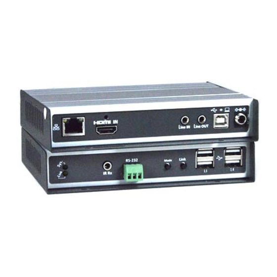
Page 5: Panel And Connectors
PANEL AND CONNECTORS Marking Description Green Blinks Slowly/Amber Off: System is System LED (Green) starting up. Link LED (Amber) Green On: System is ready, but TX/RX are not connected. Green Blinks Rapidly: TX/RX connected and communicating. - Page 6 Marking Description Green Blinks Slowly/Amber Off: System is starting up. Green On: System is ready, but TX/RX are not connected. System LED(Green) Green Fast Blink: TX/RX are connected and Link LED (Amber) communicating.
-
Page 7: Configuration
CONFIGURATION To configure the Tx/Rx through the Configuration Web page there is Setup mode and Operation mode. You can use either. We recommend Operation mode (on page 6). Setup Mode Configuration 1. To enter TX/RX Setup Mode Configuration Web page, press and Hold the TX/RX’s [Button 1]/[Link] button and Power ON until Green and Amber LED start blinking, then release the button. This will force TX/RX to enter Setup mode. 2. Directly connect TX/RX to PC LAN port and set the PC IP to 192.168.0.1, Net Mask 255.255.255.0. 3. Open the PC’s Web Browser (we recommend Chrome) and enter IP address 192.168.0.88 to enter the Setup Mode Configuration Web page. 4. The Setup Mode Configuration Web page contains a System tab with sub‐tabs Version Information, Update Firmware, Configuration, Utilities and [Statistics]. Version Information Provides information for “Tx” or “Rx”, Firmware version, IP ... -
Page 8: Update Firmware
Update Firmware Enter [Update Firmware] ‐‐‐> navigate to the firmware file (.bin) then click [Upload] to start a firmware upgrade. The firmware upgrade takes about 3 minutes, then it will display “DONE Rebooting…” to indicate the unit has been upgraded and rebooted. Configuration You can export the current settings to a configuration file, or import configuration from an external file. Enter [Configuration] ‐‐‐> Click [Save Configuration] to export configuration, click [Upload Configuration] to import configuration. Utilities Factory Default ‐‐‐> To reset the device to the factory default. Reboot ‐‐‐> To reboot the device. Compatibility mode, EDID, Console API Command ‐‐‐> See "Operation Mode Configuration" for details. Statistics Display system status for State Machine, Network, Video EDID, Video Screen attachment, Video Timing. ... -
Page 9: Operation Mode Configuration
Operation Mode Configuration To enter TX/RX Operation mode Configuration Web page: 1. Set the PC to IP 10.0.1.1, Net Mask 255.0.0.0. 2. Open a Browser (we recommend Chrome) then enter TX/RX IP address 10.xx.xx.xx 3. The TX contains 3 subtabs System, Network, Functions. The RX contains 4 subtabs System, Video Wall, Network and Functions. System Tab Version Information Same as in Setup Mode on page 4. Update Firmware Same as in Setup Mode on page 4. Configuration Same as in Setup Mode on page 5. Utilities Commands ‐‐‐> Factory Default ‐‐‐> To reset the device to the factory default. Commands ‐‐‐>Reboot ‐‐‐> To reboot the device. Compatibility mode ‐‐‐> Not applicable to this product. EDID (TX only, not in RX) The TX provides flexible EDID selections: Copy EDID from EDID Master (default) ‐‐‐> TX will get EDID from the RX with "EDID Master" setting. Resolution ‐‐‐> You can set TX with a specific resolution from the drop‐down menu. ... -
Page 10: Network Tab
Available resolutions are 3840x2160@30Hz, 2560x1440@60Hz, 1920 x 1200@60Hz, 1920 x 1080@60Hz, 1680 x 1050@60Hz,1440 x 900@60Hz, 1366 x 768@60Hz, 1280 x 1024@60Hz,1280 x 720@60Hz, 1024 x 768@60Hz, 720 x 480@60Hz. Note: The [Resolution] selection will be overwritten by the RX EDID Master if the TX is set on Unicast. DVI ‐‐‐> Enable this option if the video source is DVI‐D instead of HDMI. Console API Command ‐‐‐> Not applicable to this product. Statistics Display system status for State Machine, Network, Video EDID, Video Screen attachment, Video Timing. Network Tab IP Setup (TX/RX) The system supports Auto IP, DHCP, and Static (default) for the IP configuration: Auto IP ‐‐‐> 169.254.xxx.xxx (Auto), Subnet Mask 255.255.0.0, Default Gateway 192.168.0.1 DHCP ‐‐‐> Get IP from DHCP Server. Static ‐‐‐> Enter IP Address, Subnet Mask, Default Gateway, click [Apply]. ... - Page 11 Casting Mode (TX) The TX can be set either in Multicast (default) or Unicast mode as below: st In Multicast mode, the Multicast IP prefix (1 digit) can be configured in the range of 224 ~ 239, default is 225. nd The 2 digit is internally fixed with Video=2, Audio=3, IR=4, Serial=5, GPIO=6, USB=7, CEC=8. rd th The 3 and 4 digits are configurable in the range of 00 ~ 99. Multicast stop video streaming when no client connected: Enable this setting to stop the Tx from streaming out (reduce bandwidth) if there is no Rx connected. Disable this setting to keep the Tx streaming out (fast switching but increase bandwidth) even if there is no Rx connected. ...
- Page 12 Casting Mode (RX) The RX can be set in Multicast (default) or Unicast mode as below: In Multicast mode, you can set the Multicast IP prefix (default 225) and select the Connection Method from: First Available (default), Multicast IP, OSD Transmitter List, and Direct Connection. In Unicast mode, you can select the Connection Method from First Available, OSD Transmitter List, TX IP and Direct Connection. The RX supports the following Connection Methods: First Available: the RX will connect to the first available TX when powered ON. Multicast IP 225.2.xx.xx: the RX will connect to the TX with the same Multicast IP address specified here. OSD Transmitter List: the RX will display the available TXs in the OSD menu for user to select. Select “All Transmitters” if all of TXs are permitted. Select “Transmitter IP Range” and input the IP range with “‐“ and “,”. ...
- Page 13 For example, “10.0.30.1 – 10.0.30.30, 10.0.30.200, 10.0.92.188, …” TX IP: the RX will connect to this specified TX only. Direct Connection: this setting enables RX to connect TX by the same subnet, same Casting Mode, Jumbo Frame and EDID Master will be automatically enabled. Show TX Device name when connected (RX) This feature enables the RX to display the TX name (or IP) when connected. Default is enabled with 5 seconds of display time. Jumbo Frame (TX/RX) The TX/RX supports Jumbo Frame (8K bytes) for better video quality, default Enabled. Note: The Ethernet Switch also must be set with Jumbo Frame enabled (at least 8K) if TX has been enabled. ...
-
Page 14: Functions Tab
Functions tab Device Name (TX/RX) To set TX/RX Device name, enter ‐‐‐> [Functions] ‐‐‐> [Device Name] ‐‐‐> input name (20 characters max) ‐‐‐> [Apply] to save the Device Name. Video over IP (TX) Functions‐‐‐> Video over IP: Enable Video over IP (Default: Enabled) Video/Graphic Mode: Select [Video Mode] for smooth video play. Select [Graphic Mode] for a static picture KVM application. Maximum Bit Rate: Options are “Best Effort”, “200, 150, 100, 50, and 10 Mbps” for the TX bandwidth selection. (Default: Best Effort). Maximum Frame Rate: This provides the maximum % of the TX frames rate capture up (Default: 100%). ... - Page 15 Video over IP (RX) Functions ‐‐‐> Video over IP: Enable Video over IP (Default Enabled). Enable Video Wall: Enable this setting for the Video Wall output. Copy EDID from this Video Output: To assign this RX as the EDID Master. Scaler Output Mode: The RX is built with a scaler feature. The output resolution can be selected from these options: Auto EDID (default), Pass Through, 1080p60, 1080p50, 1920x1200, and Customize. The “Auto EDID” means the RX will output to the screen with resolution of the screen’s EDID. Timeout for detecting video lost: The timeout period for the video signal lost detection (default 10 sec.) Turn off screen on video lost: Stop the video output when video signal is lost (default Enabled) ...
-
Page 16: Compatibility Mode
USB over IP (TX) Enable USB over IP ‐‐‐> Check to enable TX’s USB over IP feature (default Enabled). It works as a 5‐port Virtual HUB when TX is attached to PC USB port. These 5 Virtual USB ports will be sequentially linked to the connected RX USB devices. There are 4 USB ports on each RX, but only the port with device attached will occupy the TX’s Virtual USB port. Operation Mode ‐‐‐> The TX USB‐over‐IP supports the Exclusive and Sharing modes: Exclusive Mode: All of TX’s 5 Virtual USB ports will be exclusively assigned to the RX which has the USB access right. The other RXs can request USB access right manually. Sharing Mode: The TX’s 5 Virtual USB ports can be shared by multiple RXs. Depending on the number of USB devices on each RX, it is possible to have maximum 5 RXs sharing the same TX’s Virtual USB. Compatibility Mode Mouse not responding well ‐‐‐> enable this setting when mouse is slow. K/M over IP ‐‐‐> The TX also built in K/M over IP HID emulation for multiple RXs to share the same TX’s keyboard/mouse. This feature will occupy one TX’s Virtual USB port when enabled (the default). ... - Page 17 USB over IP / KMoIP ports (RX) There are 2 x USB 1.1 and 2 x USB 2.0 ports on each RX. These 4 USB ports can be configured for USB‐over‐IP or KM‐over‐IP devices. The USB‐over‐IP devices will be virtually linked to the TX’s 5 Virtual USB ports; the KM‐over‐IP devices will be linked and shared with the TX’s K/M over IP HID emulation port. The advantage of USB‐over‐IP device have better USB compatibility, for example USB Touch, Disk, … devices must be configured with USB‐over‐IP. The advantage of KM‐over‐IP device is to have multiple RXs sharing the same TX’s K/M over IP HID emulation port. It is recommended to configure the 2 x USB 1.1 (keyboard/mouse) as KMoIP ports and 2 x USB 2.0 as USB over IP ports (for Touch screens, Flashdrive, etc). The RX USB over IP Configuration Web page: This USB over IP setting must be enabled for any USB devices to be attached with TX’s Virtual USB HUB. The RX KMoIP ports Configuration Web page: ...
- Page 18 Enable the port #1, 2, 3, 4 for the device to be linked with the TX’s K/M over IP HID emulation port. By default Ports 1 and 2 are KMoIP Enabled. Note: All of RX’s 4 x USB ports will be configured as KMoIP if the USB over IP is disabled. Hotkey (RX) The RX supports Hotkey for OSD Menu. To choose the RX OSD Hotkey: Function ‐‐‐> Hotkey ‐‐‐> select the Hotkey from the list: <Ctrl><Ctrl>, <Shift> <Shift>, <Alt> <Alt>, or <Scroll> <Scroll> (default: Ctrl Ctrl). ...
-
Page 19: Baudrate Setting For Type 2
Serial over IP (TX/RX) Serial over IP ‐‐‐> Enable/Disable (default Enabled). Operation Mode Type 1: for Unicast application where user can dynamically link with any target RX. Type 2: for Multicast application where TX RS‐232 will link with all of connected RXs (default). Type 1 guest: similar to type 1 but using PC to link with RX’s RS‐ 232. Type 2 guest: similar to type 2 but using PC to link with RX’s RS‐ 232. Note: Please refer to “How to Use RS232 over IP” . Baudrate Setting for Type 2 Set RS‐232 Baudrate, Data bits, Parity, Stop bits. (default 115200, 8‐n‐1) ... -
Page 20: Audio Output (Rx)
Audio Output (RX) If the TX’s input audio is HDMI, you can route the audio output on Line Out of the RX: Functions ‐‐‐> Audio Output ‐‐‐> check “HDMI Audio De‐Embedder”. Click Apply to save the setting and reboot. (default Disabled) Note: If any 3.5mm audio ports on the TX or RX are used, audio will not be routed through the HDMI cable at the RX. IR over IP (RX) It is possible to assign the IR signal routing path: Enable IR over IP (default Enabled) IR Assignment ‐‐‐> Select IR routing path from the following 3 options: Video Source TX ‐‐‐> Send the RX’s IR input signals to the TX of current video source. ... - Page 21 Multi‐Screen Setting (TX) The system supports Multi‐Screen feature which is useful for PC with multiple screen outputs. As above TX [Multi‐Screen Setting] Web page: Main Video: Enable this setting if this TX is connected to the PC’s main video output. Note: Any TX with [Main Video] setting disabled will not be shown on the OSD Transmitter List. nd Video TX IP: Type in TX IP address which is connected to the PC’s nd video out. rd Video TX IP: Type in TX IP address which is connected to the PC’s rd video out. th Video TX IP: Type in TX IP address which is connected to the PC’s th video out. ...
- Page 22 Multi‐Screen Setting (RX) As shown above in the RX Multi‐Screen Setting Web page: nd Screen RX IP: Type in RX IP address which is connected to the nd screen. rd Screen RX IP: Type in RX IP address which is connected to the rd screen. th Screen RX IP: Type in RX IP address which is connected to the th screen. When the Main RX switches to a new TX, its associated RXs will also be switched to the new TX’s associated TXs automatically. Mirror (RX) When the “Mirror” option is enabled, the associated RXs will connect to the same TX as the Main RX is connected to. This splitter function enables multiple RXs to display the same TX. ...
-
Page 23: Video Wall Configuration(Rx)
VIDEO WALL CONFIGURATION(RX) ... -
Page 24: Basic Setup
The RX comes with Video‐Wall feature, multiple RXs can receive the same video stream and display on multiple screens in a grid. You can setup the Video‐Wall either by using Video‐Wall Manager software, or OSD (On Screen Display) or the Web page. For the Video‐Wall Manager setup and operation, please refer to “Video‐Wall Manager Setup Guide”on our website. For the OSD setup and operation, please refer to “Video‐Wall OSD Quick Setup Guide”. The following section provides information for the Video‐Wall Web page setup. Basic Setup Enter RX Web page ‐‐‐> Video Wall ‐‐‐> Basic Setup. Bezel and Gap Compensation Enter the value for OW (Outside Width), OH (Outside Height), VW (View Width), VH (View Height) in 0.1mm units ‐‐‐> Apply. With these 4 values, the system can calculate the screen Bezel and Gap size. Wall Size and Position Layout Select the value for Vertical Monitor Count, Horizontal Monitor Count, Row Position, Column Position from the drop‐down menu ‐‐‐>Apply. With these 4 values, the system can calculate the Rx grid position within the Video‐Wall. Preferences Stretch Type ‐‐‐> Select ”Fit In” or “Keep Aspect Ratio” ‐‐‐>Apply Clockwise Rotation ‐‐‐> Select 0, 180, 270 ‐‐> Apply Note: Fit In: Stretches or compresses the broadcast screen to fill the whole wall. Keep Aspect Ratio: keeps strict picture aspect ratio. If there is a mismatch, some image may fall beyond screen edges. ... -
Page 25: Show Osd
The following screenshot shows couple examples of Fit In and Keep Aspect Ratio: Show OSD To identify the screen, check the “Show OSD” and select the device then click Apply button. Video-Wall Advanced Setup The Advanced Setup can be used for special effects which are not included in Basic Setup. There are two steps in advanced setup: Step 1: Choose one or more target RXs to apply setup to. Step 2: After the targets are selected, changes can be applied in Step 2. ... - Page 26 Show OSD To identify the screen, check the “Show OSD” and select the device then click Apply button. Reset to Basic Setup ‐‐‐> Reset the target(s) to the setting of “Basic Setup”. Stretch Type Fit In: Stretch the full screen to the whole wall. Keep Aspect: keeps picture aspect ratio; some image may spill off screen if needed. Clockwise Rotate 0: No rotation 180: clockwise rotate 180 degrees 270: clockwise rotate 270 degrees ...
- Page 27 ...
- Page 28 Screen Layout (Row x Column) Define the Video Wall size, select the Row and Column count from the drop‐down menu. Row Position: Set the Row position for the selected target RX. (start from 0) Column Position: Set the Column position for the selected target RX. (start from 0) Horizontal Shift: Shift target screen horizontal to left/right in 1 pixel units. Vertical Shift: Shift target screen vertically up or down in 1 pixel units. Horizontal Scale Up (N pixels/column_count): Scale up the target screen horizontally, by pixels (1/column count). Vertical Scale Up (N pixels/column_count): Scale up the target screen vertically, by pixels (1/row count). ...
-
Page 29: Installation
INSTALLATION 1. The factory default Connection Method for RX is “First Available”, and TX is in Multicast mode with its default Multicast IP (shown on the label). It means all TXs will send packets with default Multicast IP (225.2.xx.xx), and all RXs will find the first available TX for connection. 2. Use a CAT6 UTP cable (straight, EIA 568B) to directly connect TX/RX as a pair connection, or connect to IGMP enabled Gigabit Ethernet switch for many‐to‐many installation. Note: Each TX comes with individual factory default Multicast IP which is shown on the unit label. 3. Connect TX/RX to video source/screen by HDMI cable. 4. The TX factory default EDID setting is “Copy EDID from EDID Master“, please perform step 4.1/4.2 to assign a RX as the EDID Master. (The Tx has internal built‐in EDID of “KVM over IP” with resolution 1080p if there is no any Rx set as EDID Master) Or you can change and use the TX built‐in EDID as step 4.3: Press and hold the [Mode] button of the specific RX unit and power ON until Green LED blinking then releasing the [Mode] button, this RX will be assigned as EDID Master (RX’s Green LED will blink, then steady ON, and Amber LED Off to indicate it is ready and waiting for connecting with TX). Then power ON other RX units sequentially. Refer page 10, enable “Copy EDID from this Video Output” to assign a specific RX as EDID Master. To use TX built‐in EDID for specific Resolution, refer to page 6 “Resolution Selection”. ... -
Page 30: Usb Over Ip And Km Over Ip Installation
5. The following start‐up messages will be displayed during RX power on: FW: 20‐Aug‐28 A7.4.2.2 (Firmware date and version) Local IP: 10.0.99.33 (RX’s IP address) MAC: 0020FExxxxxx (RX’s MAC address) Connection Method: First Available Remote IP: 10.0.x.x / 225.0.x.x (Connecting target TX IP / Multicast IP) 6. To get the best video performance, please refer to page 9 to enable TX/RX Jumbo Frame setting, and set Ethernet Switch Jumbo Frame with minimum 8K bytes. 7. Attach HDMI/DVI source to the TX’s HDMI In. Then power ON the TX unit, the Green LED will blink then go steady ON to indicate ready and waiting for connecting with RX. 8. As long as TX/RX connection established, both TX and RX Amber LED will start to blink, indicating waiting for video input source (Green LED is ON). 9. If you are using PC as video source, check the correct screen EDID is shown on PC graphic control panel. 10. Activate video with audio source to TX, then check if all RXs are correctly displayed. In this step, the Green LED is fast blinking and the Amber LED is ON to indicate the unit is ready and video source is also ready. USB over IP and KM over IP installation 11. Connect TX USB‐B to PC, OS will detect a Generic USB 2.0 Virtual Hub Device. ... -
Page 31: Tx/Rx Panel Button Operation
It is not necessary to gain USB access right for the KM over IP port. The TX (PC) can be shared with multiple RXs for keyboard/mouse access in KM over IP mode. 13. There are 4 USB‐A ports on the RX. The factory default setting for the TX is both USB‐over‐IP and KM‐over‐IP enabled; RX USB‐over‐ IP enabled, USB 1.1 KMoIP enabled and USB 2.0 KMoIP disabled. 14. There are 2 methods to gain the access rights for a USB‐over‐IP port: 14.1 Keep pressing 3 sec. the RX Link button. 14.2 Press “U” key to toggle during Transmitter List OSD menu. The RX display “Requesting USB” to indicate starting USB‐over‐IP connection, and message of “Starting USB” will be displayed if it successfully gained the USB access rights. Meanwhile, the previous USB Master unit will show an OSD message of “USB Stopping”. Tx/Rx Panel Button Operation Press TX "Button 1" button to lock/unlock RX Keep pressing TX Button 1 button for 3 seconds will lock/unlock the RX’s USB and KMoIP ports. The RX will display “Locked by TX” OSD message on the screen when it is locked. Press TX "Button 2" or RX "Mode" button to select Video/Graphic mode ... - Page 32 Configuration” OSD Menu Press RX’s Link button for the Transmitter List OSD Menu as the below. Short press the button again to move the highlight arrow “>” to select the TX, the RX will connect to the selected TX after 3 seconds. From the Transmitter List OSD Menu, keep pressing the Link button for 3 seconds will enter Simple Configuration OSD Menu as the below screenshot. Short press the button to move the highlight arrow “>” to select the setting to change. You can change Casting Mode, TX Maximum bit rate, Connection Method and RX ON/OFF (temporary Connect/Disconnect with TX). Move the highlight arrow “>” to [Hotkey Setting], wait a few seconds, the sub‐menu will show up with 4 possible selections: “Ctrl Ctrl”, “Shift Shift”, “Alt Alt”, or “Scroll Scroll”. Press Link button to move the highlight arrow “>” to the desired selection. The RX unit will be re‐booted. ...
-
Page 33: Rx Hotkey Osd Menu
Rx Hotkey OSD Menu The Rx supports Graphic OSD Menu from firmware version A7.4.2.2. There are 2 type of A7.4.2.2 firmware for Rx unit: OSD Tx List firmware and OSD Console firmware. Rx with “OSD Tx List” firmware Press <hotkey> <hotkey> at Rx keyboard will activate the OSD Tx List Menu. If the Rx has not been connected with any Tx, the OSD Tx List st nd Menu is as below, the 1 line shows “TX:not connected”, the 2 line shows the current Rx name and IP address. ... - Page 34 To connect to a Tx: Select a Tx by mouse or↑↓then click Connect button to make connection. If the Rx already connected with a Tx, the OSD Tx List Menu is as below, the st line shows the connected TX name and IP address with a ”Disconnect” nd button, the 2 line shows the current Rx name and IP address with a “USB ON/OFF” button. ...
- Page 35 To Start/Stop Current Rx USB over IP: Press USB ON/OFF button. To refresh Tx List: Press F5 Refresh button. To switch OSD in Transparency/Background Mode: Press F8 Mode button. To Disconnect with the current Tx: Press the Disconnect button. To end the OSD: Press <ESC> ...
-
Page 36: Specifications
SPECIFICATIONS Local/Transmitter (TX) Ports HDMI‐ Female x1 RJ45 Female x1 USB Type B Female x1 Screw Terminal (RS232) 3.5mm Jacks x2 (Mic In/Audio Out) 3.5mm Jack x1 (IR emitter‐ sold separately) Computers supported PC, SUN and MAC with Ultra‐HD HDMI output Remote/Receiver (RX) Ports HDMI‐ Female x1 RJ45 Female x1 USB Type A Female x4 (2x USB 1.1 and 2x USB 2.0) Screw Terminal (RS232) 3.5mm Jacks x2 (Mic In/Audio Out) 3.5mm Jack x1 (IR emitter‐ sold separately) Ultra‐HD 4Kx2K resolutions (3840x2160 @ 30Hz) Video Resolutions 2K Cinema (2048x1080 @ 60Hz) supoported HDTV resolutions to 1080p Computer resolutions to 1920x1200 Audio support Supports embedded digital audio through HDMI compatible TVs or audio receivers. RS232 Communication Supports TXD and RXD Baud rate 9600/14400/19200/38400/57600/115200 ...
Need help?
Do you have a question about the XTENDEX Series and is the answer not in the manual?
Questions and answers