
Related Manuals for Chint Power CPS SC4.6KTL-O


Summary of Contents for Chint Power CPS SC4.6KTL-O
- Page 1 CHINT Grid PV-Inverter CPS SC4.6KTL-O Installation and Operation Manual Version 2.0E...
-
Page 2: Table Of Contents
Contents Before you start......................4 Safety Instructions ..................5 Limited Warranty ..................7 Overview ......................8 3.1. Introducing the Grid PV System ............8 3.2. Introducing the Grid PV Inverter ............9 3.3. Front Panel LEDs ................10 Features ...................... 11 Installation .................... - Page 3 9.2 Checking and Maintenance .............. 44 Specifications ....................46 Disposal ....................... 49 Contact Information ................... 50 Compliance of Standards ................51 Load Graph and Efficiency Graph............. 52 Appendix I: VDE Certification ................53...
-
Page 4: Before You Start
Before you start Congratulations on choosing CHINT Grid PV-Inverter (referred to in this manual as “PV-Inverter”, or simply “Inverter”). This PV-Inverter is a highly reliable product due to its innovative design and perfect quality control. The device is dedicated to high-demand, grid-linked PV systems. -
Page 5: Safety Instructions
1. Safety Instructions 1. Do not remove the casing. Inverter contains no user serviceable parts. Refer servicing to qualified personnel. 2. Both AC and DC voltage sources are terminated inside the PV-Inverter. Please disconnect these circuits before servicing. 3. When the Photovoltaic panel is exposed to sunlight, it generates a DC voltage. - Page 6 Hot Surfaces Although designed to meet all safety requirements, some parts and surfaces of the inverter are still hot during operation. To reduce the risk of injury, do not touch the heat sink at the back of the PV-Inverter or nearby surfaces while it is operating.
-
Page 7: Limited Warranty
2. Limited Warranty This INVERTER comes with a 5-year warranty. An optional extended warranty may be available by special request before delivery. This warranty covers all defects due to design, manufacturing and components. This warranty does not cover damages resulting from: ... -
Page 8: Overview
3. Overview 3.1. Introducing the Grid PV System The Grid PV System is mainly composed of 4 parts: the PV-panels, the PV-Inverter, the AC-Connection Unit (the connection Interface) and a connection to the Public Utility. When a PV-panel is exposed to sunlight and connected to an inverter, it generates DC power. -
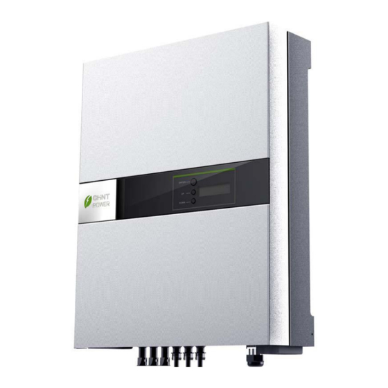
Page 9: Introducing The Grid Pv Inverter
(4) AC Output Optional Communication Port and Cover Connector CHINT CPS SC4.6KTL-O Inverter (1) Connection Panel: The connection panel contains DC and AC terminals, and communication ports as detailed below. (2) Heat-sink: Part to dissipate heat produced by the inverter (3) 3 pairs of DC-input terminals: Each input pair consists of positive and negative terminals. -
Page 10: Front Panel Leds
3.3. Front Panel LEDs There are 2 LED’s on the inverter, one is green and the other is red. Normally, only the green LED will turn on during operation. Their indicated status are explained as follows: Power on (green LED): It lights when inverter is running. The only condition it will be dark is no power provided to inverter. -
Page 11: Features
4. Features Very high conversion efficiency (up to 96%) 3 MPP (Maximum Power Point) trackers, independent or parallel operation IP65 compliant for outdoor application Embedded LCD, displaying status and system information Fanless design, quiet operation ... -
Page 12: Installation
5. Installation 5.1. Inside the Package The following items are included with this Inverter package: (1) One PV-Inverter (2) Installation and Operation Manual (3) 4 Mounting Screws and 4 Snap Bushings (4) 2 Safety-lock screws (5) Rubber Bushing (6) Mounting Bracket 5.2. - Page 13 Inverter is being installed away from explosive vapors. No flammable items are to be near the inverter. ...
- Page 14 1. Choose a dry place, out of direct sunlight with ambient temperature between 0 and 40° C. 2. Select a wall or solid, vertical surface which is strong enough to support the inverter. 3. The PV-inverter requires adequate cooling space for heat dispersal.
- Page 15 4. Fix the bracket by using outer mounting holes: (a) To install the device to a wall, mark 4 outer holes at the back of the bracket as illustrated below. 367 mm 267 mm (b)Drill the 4 marked holes in the wall, and then drive in the 4 Snap Bushings.
- Page 16 5. Fix the bracket by using central mounting holes: (a) To install the device to a narrow upright, mark 3 central holes at the back of the brackets as illustrated below. (b) Drill the 3 marked holes in the wall, and then drive in the 3 snap bushings.
- Page 17 7. Insert the Safety Lock screws to fix the PV-Inverter in place. 8. Ensure the device is properly fixed to the bracket.
-
Page 18: Connecting The Ac-Output Cable
5.3. Connecting the AC-Output Cable Connect PV-Inverter to the AC-Connection unit via the AC-output cable as following steps: (1) Unscrew those four screws around terminal block, keep them for AC cover screwing later. (2) Find rubber bushing in accessory box, cut a suitable hole in it for feeding AC cable. - Page 19 (6) Screw AC cover to chassis firmly, then screw cable gland to lock cable with AC cover together. Ø Ø...
-
Page 20: Connecting The Pv-Panel
5.4. Connecting the PV-Panel (1) First make sure the maximum open circuit voltage Voc of each PV string is below 750VDC UNDER ANY CONDITION. (2) Always connect PV-Panel positive (+) terminal to PV-Inverter DC positive (+) terminal, and the PV-Panel negative (-) terminal to PV-Inverter DC negative (-) terminal. -
Page 21: Connecting To The Connection Unit
(4) To fully optimize the PV DC output set-up, use the following configuration guidelines: (a) For PV DC output less than 8.5A, use a single pair of PV-Inverter DC terminals. (b) For PV DC output between 8.5A and 17A, use two sets of inverter DC terminals. - Page 22 (2) After the PV-Panels are connected to the PV-Inverter, the output voltage is greater than 100VDC and the AC grid is not connected to the inverter, the LCD displays “Model= XXXXXX”-> “Waiting”-> “No Utility”. The RED “fault LED” turns on. Initial Display before Connecting to the Public Utility (3) Check the connection between PV-Inverter and AC Connection System.
-
Page 23: Operation Of Pv-Inverter
6. Operation of PV-Inverter 6.1. Initialization for Regulation Type Setting The Inverter provides a “Initialization” function at the first time start-up as an process in which user is able to select the intended regulation type before normal operation. The inverter will not able to operate normally before regulation setting is completed even though it is connected correctly at both DC input and AC output. - Page 24 then press the button for 5 more seconds unitl “INIT OK” message appeared, the regulation setting is completed. INITIALIZATION Pac=xxxxW Press button (1sec) VDE0126-1-1 Pac=xxxxW “INIT OK” indicate Regulation type setting is completed Press button (1sec) INIT OK RD1663 Pac=xxxxW Pac=xxxxW Press button (5sec) to set Press button (1sec)
-
Page 25: Auto-Power
6.2. Auto-power The PV-Inverter starts up automatically once DC-power from the PV-Panel is sufficient. There are 3 modes of operation. 6.3. Operating Modes 1. Normal In this mode, the PV-Inverter automatically detects the system status and selects the best mode of operation. If the power from the PV-Panel is greater than 150VDC, the supply is converted to AC fed in to the grid. - Page 26 4. Three Operating States: Standby, Waiting, Normal During normal operation, the PV-Inverter enters a ‘standby’ state at voltages below 100V. Between 100V and 150V the device enters the ‘waiting’ state and begins checking its own internal status. The ‘Normal’ state is entered when the voltage is above 150V. The following example shows the LCD when the PV-Panel input increases above 100V: The LCD first displays the model name...
-
Page 27: Using The Lcd Display
Before connecting PV-Panels to DC terminals, make sure the polarity of each connection is correct. An incorrect connection could permanently damage the device. 6.3. Using the LCD Display Use the Function Button to customize the LCD display settings, or view further information about the internal status of the PV-Inverter. - Page 28 Pressing the Function Button seven Energy = XXXKWh times displays the Model No. of Pac = XXXX.XW the Inverter CPS SC4.6KTL-O Pressing Function Button nine times Pac = XXXX.XW displays the firmware version Ver xx.xx Pressing the Function Button a tenth Pac = XXXX.XW...
- Page 29 Contrast Repeatedly press the Function Pac = XXXX.XW Button until the contrast reaches the desired level Contrast After the highest level is reached, the Pac = XXXX.XW contrast starts to decrease A few seconds delay and the display Contrast automatically returns to its “Normal” Pac = XXXX.XW display Normal State...
- Page 30 Locking the display To lock the current display (for example, Frequency), press and hold Frequency= XX.XHz the Function Button for about a Pac = XXXX.XW second Lock The screen displays “Lock” then returns Pac = XXXX.XW to the previous screen Frequency= XX.XHz Pressing the Function Button on the Pac = XXXX.XW...
-
Page 31: Auto Test Setting (Only For Enel Guide 2010 Model)
6.4. Auto Test Setting (Only for ENEL GUIDE 2010 model) The Inverter is supplied with an auto test function which enables the user to check that the protection interface is operating correctly. In order to select this function, press the function button until the message "AUTO TEST SET"... - Page 32 Auto Test Setting If the threshold and the grid voltage are equal, the PV Inverter switches to fault. Display shows a message similar to this switch-off time OK. Upper frequency threshold will be checked. Display shows variation between upper frequency threshold and mains supply.
- Page 33 Auto Test Setting If all the above tests have been performed, the display shows the message TEST PASSED. PV Inverter switches to normal operation mode. If one of the above tests failed, the display shows the message AUTO TEST FAILED. PV Inverter switches automatically and permanently to fault status.
-
Page 34: Auto Test Record (Only For Enel Guide 2010 Model)
6.5. Auto Test Record (Only for ENEL GUIDE 2010 model) After the Auto test setting, inverter will record the test result values, as shown in below. **Press the button for 5 seconds, the messages shown on the screen will change per second. -
Page 35: Maximum Power Point Tracking (Mppt)
6.6. Maximum Power Point Tracking (MPPT) Due to its advanced design, the PV-Inverter can track the maximum power from any PV-Panel under any condition. When the output power display is stable, the PV-Inverter is converting the maximum power available. When the power reading fluctuates, the device is tracking power changes due to varying levels of sunlight. -
Page 36: Lcd Display Messages
6.7. LCD Display Messages Operating In English In German In Italian Description conditions Normal Working Status PV inverter is totally shutdown, V Power off <=90V Standby Standby Standby Standby 90V< Input voltage < =120V Input voltage range 120~150V during start-up. After PV voltage is higher than Initialization &... - Page 37 Operating In English In German In Italian Description conditions Instantaneous Output Pac = xxxx.xW Pac = xxxx.xW Pac = xxxx.W The real time output power in xxxx W power Accumulated energy Total energy to has been fed to grid Energy=xxxxxxkWh Eac = xxxxxxkWh Energy = xxxxxxkWh information...
- Page 38 Operating In English In German In Italian Description conditions Earth fault of the PV-panels or failure of Isolation failure Isolation fault Isolationsfehler Err.Isolamento surge voltage protection Leakage current on ground conductor is GFCI active Ground I fault Fehlerstrom I dispers.Alta too high Grid measured data is beyond the Grid failure...
- Page 39 Operating In English In German In Italian Description conditions Output DC injection DC INJ High DC INJ zu hoch Idc uscita alta Output DC injection too high too high EEPROM inside has data access EEPROM problem EEPROM Failure EEPROM Fehler Err.interno 02 problem Communication...
- Page 40 Operating In English In German In Italian Description conditions Model display CPS SC4.6KTL-O CPS SC4.6KTL-O CPS SC4.6KTL-O Inverter model name LCD contrast Contrast Kontrast Contrasto The top menu of LCD contrast setting LCD contrast setting Set Contrast Kontrast Regola contrasto...
-
Page 41: Communication Interface
Use “Pro Control” to monitor status of multiple inverters. Firmware upgrades are also available via this interface. CPS SC4.6KTL-O is integrated with a DB9 socket for the RS232 interface. Remove the DB9 socket cover before use. Pin assignment of this DB9 socket is stated as below: N.C. -
Page 42: Troubleshooting
8. Troubleshooting The PV-Inverter requires very little maintenance. When unexpected situation occurs, please refer to the following table should further assistance be required before calling your local dealer. The following table lists common fault messages that display when the fault LED is lit, and their solutions. Troubleshooting the PV-Inverter Fault Diagnosis and Solution... - Page 43 Troubleshooting the PV-Inverter Fault Diagnosis and Solution Message Consistent (1) Disconnect PV(+) and PV(-) from the input, start the unit again. Fault (2) If it does not work, please call service. SCI Failure (1) The internal temperature is higher than specified normal value.
-
Page 44: Preventative Maintenance
9. Preventative maintenance Although PV-Inverter requires very little maintenance, the following inspections at regularly would help to ensure PV Inverter operation with optimal performance. 9.1 Visual Inspection Check the inverter and cables for any signs of external damage. Contact your installer immediately if you find any defects. Do not carry out any repairs on your own. -
Page 46: Specifications
10. Specifications Model CPS SC4.6KTL-O Input (DC) Nominal DC voltage 600 V Max. PV open voltage 750V System start-up voltage Typical 120 V Initial feeding voltage 150 V Shutdown voltage Typical 90V Working voltage range 100 ~ 750 V Full rating voltage range... - Page 47 Model CPS SC4.6KTL-O O/P current distortion (THD i) < 3% Power Factor > 0.99 Operational voltage range (F/W 190~256V Setting) Disconnection time of excess ≦0.2 sec. operational voltage range Operational frequency range (F/W Germany 47.55~50.15Hz Setting) (DE) Disconnection time of excess ≦0.2 sec.
- Page 48 Model CPS SC4.6KTL-O Heat dissipation Convection Operating temperature range -20 ~ +55℃ Humidity 0 to 95%, non-condensing Communication RS232 standard RS485 optional. Hazard substance restriction Lead free, complied with RoHS GP2 Standard protocol, Eaton Phoenixtec MMPL proprietary RS485 Protocol protocol...
-
Page 49: Disposal
11. Disposal The dealer or installers should remove the PV Inverter from the array and contact the supplier for disposal instructions The inverter must not be disposed of with the household waste. Dispose of the PV Inverter at the end of its service life should be done in accordance with the disposal regulations for electronic waste which apply at the installation site at that time. -
Page 50: Contact Information
• Serial number of the PV Inverter • Type and number of PV panel connected • Fault message • Communication method SHANGHAI CHINT POWER SYSTEMS CO., LTD. Add: Building 4, No.855 Wenhe Road, Songjiang District, Shanghai, 201614, China Tel :+86 - 21 - 3779 1222 Fax:+86 - 21 - 3779 1222 - 6016 Service Hotline:+86 - 21 - 3779 1222 - 6300... -
Page 51: Compliance Of Standards
13. Compliance of Standards Regulatory Type Compliance of Standard VDE0126-1-1 (DE) Grid interface regulation ENEL Guide 2010 (IT) Safety DIN EN 50178 (4.98) (VDE0160) (IEC62103) EMC: EN 61000-6-2 EMS / EMI EN 61000-6-3 LVD: 2006/95/EC EMC: 2004/108/EC... -
Page 52: Load Graph And Efficiency Graph
14. Load Graph and Efficiency Graph The relationship between PV input voltage (V ) and input power (P is shown in the following example. Formula Curve Load Graph P (W)=8.5 x V Example: For Input VDC > 450V, IP = 3825 W For Input VDC ≦... -
Page 53: Appendix I: Vde Certification
Appendix I: VDE Certification...
Need help?
Do you have a question about the CPS SC4.6KTL-O and is the answer not in the manual?
Questions and answers