
Related Manuals for Chint Power CPS SCA50KTL-DO/US-480


Summary of Contents for Chint Power CPS SCA50KTL-DO/US-480
- Page 1 物料: CPS SCA50/60KTL-DO/US-480 英文版说明书 料号: 9.0020.0334A0 纸张大小: 大 32 开 封面制作要求: 200g 铜版纸附亚膜封面彩色印刷 内页制作要求: 70g 除静电双胶纸黑白印刷...
- Page 2 CPS SCA Series Grid-tied PV Inverter CPS SCA50KTL-DO/US-480 and SCA60KTL-DO/US-480 Installation and Operation Manual - Rev 2.1 CHINT POWER SYSTEMS AMERICA CO.
-
Page 3: Table Of Contents
Table of Contents Before You Start… ....................1 Chapter 1 IMPORTANT SAFETY INSTRUCTIONS ........2 Chapter 2 Overview ..................... 5 2.1 Inverter for grid-tied PV systems ............. 5 2.2 Product Features ................5 2.3 Product Protection Functions ............6 2.4 Schematic Diagram and Circuit Design ........... 7 2.5 Appearance and Main items Description .......... - Page 4 Chapter 6 Operation..................... 100 6.1 Start-Up ..................100 6.2 Shut-Down ..................100 6.3 Operation Mode ................101 6.4 Grid-tied Power Generation ............103 Chapter 7 Maintenance and De-installation ............104 7.1 Fault Shutdown and Troubleshooting ..........104 7.1.1 LED Fault and Troubleshooting ..........104 7.1.2 LCD Fault and Troubleshooting ..........
-
Page 5: Before You Start
This Installation and Operation manual contains important information, safety guidelines, detailed planning and setup information for installation, as well as information about configuring, operating and troubleshooting the CPS SCA50KTL-DO/US-480 and CPS SCA60KTL-DO/US-480 3-Phase String Inverters. Be sure to read this manual carefully before operating or servicing the inverters. -
Page 6: Chapter 1 Important Safety Instructions
Chapter 1 IMPORTANT SAFETY INSTRUCTIONS (SAVE THESE INSTRUCTIONS) Please read this user manual carefully before installation of the product. CPS reserves the right to refuse warranty claims for equipment damage if the user fails to install the product according to the instructions in this manual. Warnings and symbols in this document DANGER: DANGER indicates a hazardous situation which, if not avoided, will... - Page 7 Markings on the product HIGH VOLTAGE: This inverter operates with high voltages. All work on the inverter must only be performed as described in this document. HOT SURFACE: The inverter is designed to meet international safety standards, but surfaces can become hot during operation. Do not touch the heat sink or peripheral surfaces during or shortly after operation.
- Page 8 Do not connect the AC output of the inverters directly to any private electric utility power equipment. CAUTION: CPS SCA50KTL-DO/US-480 and SCA60KTL-DO/US-480 inverters weigh approximately 56kg (123.5 pounds). The wirebox portion weighs approximately 15kg (33 pounds).
-
Page 9: Chapter 2 Overview
Chapter 2 Overview 2.1 Inverter for grid-tied PV systems CPS SCA50KTL-DO/US-480 and SCA60KTL-DO/US-480 3-Phase String Inverters are designed for use with carport, commercial rooftop, and large utility scale PV grid-tied systems. The system is generally made up of PV modules, a 3-Phase String Inverter with a fused combiner/disconnect, and AC power distribution equipment (Figure 2-1). -
Page 10: Product Protection Functions
Long Service Life: Uses thin-film capacitors to extend inverter's service life 3 MPPTs: Multi-channel MPPT (Maximum Power Point Tracker) enable maximum design flexibility and energy harvest optimization over the life of the system. Wirebox option: The wirebox enables fused input of either discrete wiring using the Standard wirebox, or an optional H4 wirebox with quick-fit connectors for connection of industry standard cord sets. -
Page 11: Schematic Diagram And Circuit Design
2.4 Schematic Diagram and Circuit Design The basic electrical schematic diagram of CPS SCA50KTL-DO/US-480 and SCA60KTL-DO/US-480 inverters are shown in Figure 2-2. The input from PV source circuits passes through surge protection circuitry, DC EMI wave filters, and independent DC-DC boost circuitry to achieve maximum power point tracking and boost the voltages to a common DC bus. -
Page 12: Appearance And Main Items Description
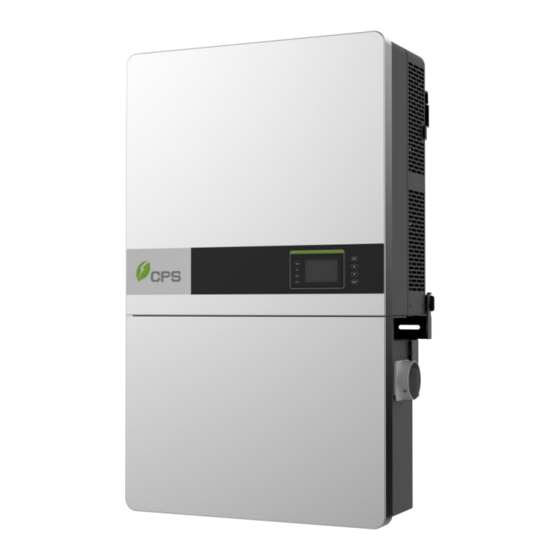
2.5 Appearance and Main items Description 5 6 7 Figure 2-3 Diagram of the CPS SCA50KTL-DO/US-480 and SCA60KTL-DO/US-480 Inverters Main items of the Inverter: 1) Main inverter enclosure 2) Inverter wirebox 3) Inverter mounting bracket 4) Cooling fans 5) LED indicator lights... -
Page 13: Anti-Islanding Detection
2.6 Anti-islanding Detection The SCA50KTL-DO/US-480 and SCA60KTL-DO/US-480 inverters include Unintentional Islanding detection as required by UL1741/IEEE1547. The inverter will continuously make bi-directional perturbations to the frequency of the output current by injecting a small amount of reactive power in order to detect a possible islanding condition. -
Page 14: Chapter 3 Installation
Chapter 3 Installation This chapter describes the planning and installation procedures for the SCA50KTL-DO/US-480 and SCA 60KTL-DO/US-480 inverters. Please read carefully and install the products following the step-by-step instructions. The inverter and other main items are shipped in two separate packages, consisting of A.) the main inverter enclosure and B.) the wirebox, mounting bracket, user manual, and accessory kit. - Page 15 Note that the items in the Accessory Kits vary between the Standard wirebox and H4 wirebox, the items listed below: Table 3-2 Accessory Kit (Standard wirebox) Q’ty Item Note For attaching the mounting bracket to M8 Expansion Anchors a concrete wall or surface M8×25mm machine bolts with integrated Used with M8 expansion anchors...
- Page 16 Table 3-3 Accessory Kit (H4 wirebox) Q’ty Item Note For attaching the mounting bracket to M8 Expansion Anchors concrete wall or surface M8×25mm machine bolts with integrated Used with M8 expansion anchors lock washer 4 for securing the wiring box to the M6 X18mm Phillips main enclosure;...
-
Page 17: Recommendations Before Installation
3.1 Recommendations before Installation See Chapter 8, Technical Data for specification ranges and limits NOTICE: allowable ambient temperature range SCA50KTL-DO/US-480 and SCA 60KTL-DO/US-480 inverters is defined based on the following conditions; Condition 1: -40C to 70C, Inverter not installed, and in storage (in packaging or unpackaged). -
Page 18: Mechanical Installation
3.2 Mechanical Installation 1) Dimensions Figure 3-1 Dimensions of CPS SCA50/60KTL-DO/US-480 Inverter 2) Installation Method (see Figure 3-2): Ensure that the mounting structure (wall, rack, roof, etc) is suitable to support the weight of the inverter. Follow the mounting guidelines below: (a) If the location permits, install the inverter vertically. - Page 19 Shade cover Figure 3-2 Inverter Mounting Options NOTICE: When the inverter is mounted backwards by ≤30° in an outdoor environment, the CPS shade cover accessory must be installed on the inverter to avoid direct sunlight.
- Page 20 3) Installation Space Requirement (see Figure 3-3): The distances between the inverters or the surrounding objects should meet the following conditions: NOTICE: The spacing between two adjacently mounted inverters must be ≥500mm (19.7 inches). Spacing should be enlarged for installation locations with ambient temperature higher than 45°C.
- Page 21 8in. 12in. 12in. 12in. Figure 3-4 Inverter Pillar or Column Mounting Dimensions INSTRUCTION: If the inverter is installed on a pillar or column (instead of solid wall), the space from the bottom of one inverter to the top of the inverter below may be as small as 12in (300mm).
- Page 22 4) Mounting the Inverter onto the Bracket (1) Mark the 8 holes on the wall or bearing surface for attaching the inverter mounting bracket as shown in Figure 3-5. 350mm 250mm 250mm ≥ (13.8in.) (9.84in.) (9.84in.) 8-? 10.0 1100mm(min.) ≥ 480~500mm (43.3in) (18.9~19.7in)
- Page 23 (2) Drill holes at the marked positions with a 10mm (0.4in.) masonry bit and insert the M8 Expansion Anchors ① into the holes; Fasten the Mounting Bracket ② with the M8x25 Assembling Bolts ③ supplied with the Accessory Kit. Figure 3-6 and 3-7. Tools Required: Electric drill (Ф10mm/0.4in.
- Page 24 Manual mounting: Two people are required to safely lift the inverter by the handle positions marked in Figure 3-9, and mount it onto the bracket. CAUTION: The main enclosure of the CPS SCA50KTL-DO/US-480 and SCA60KTL-DO/US-480 inverters is approx 56kg (123.5 pounds). Ensure the mounting bracket is properly installed and secured before hanging the inverter on the bracket.
- Page 25 Figure 3-9 Grab Handle Position (4) Install the wiring box ① Remove the cover plate at the bottom of the main enclosure. (see Figure 3-10) Tool required: No.2 Phillips head screwdriver Figure 3-10 Main Enclosure Cover Plate...
- Page 26 ② Remove screws securing the bulkhead cover at the top of the wiring box. (see Figure 3-11) Figure 3-11 Wiring Bulkhead Cover Save the bulkhead cover and screws, and attached the cover to the left side of the wiring box after the wiring box is attached to the inverter enclosure (see step 6, Figure 3-13) Tool required: No.2 Phillips head screwdriver ③...
- Page 27 Figure 3-12 Installation of the Wiring Box (5) Attach the main enclosure and the wiring box to the mounting bracket with the M6x18 screws (6 pcs). (see Figure 3-13) Tool required: No.3 Phillips head screwdriver, torque value of 4N.m (35.4in-lbs) Figure 3-13 Secure the Main Enclosure and Wiring Box to the Bracket...
- Page 28 (6) Attach the cover shown in Figure 3-11 to the left side of the wiring box. (see Figure 3-14) Tool required: No.2 Phillips head screwdriver, torque value of 1.6N.m (14.2in-lbs) Standard wirebox H4 wirebox Figure 3-14 Attach the Cover to the left side of the Wiring Box...
- Page 29 (7) Optional - Install an anti-theft padlock when the installation is complete. The anti-theft padlock is used to prevent the inverter from being stolen when the equipment is installed outdoors. The inverter may be locked to the bracket, as shown in Figure 3-15: Figure 3-15 Location of the Anti-Theft Padlock The anti-theft padlock shackle should meet the requirements of the dimensions shown in Figure 3-16:...
-
Page 30: Electrical Installation
3.3 Electrical Installation 3.3.1 Removing/Replacing the Wiring Box Cover: Prior to installation, confirm the wiring box used as either the Standard wirebox as shown in Figure 3.17(a) or H4 wirebox (Optional) as shown in Figure 3.17 (b). Figure 3.17 (a) Standard wirebox Figure 3.17(b) H4 wirebox (1) Use a No.3 Philips head screwdriver to remove the 4 screws on the wiring box and remove the cover. - Page 31 INSTRUCTION: It is important to use hand tools (e.g. Screwdriver or T-handle, #3 Phillips) and not power drivers or other types of screw drivers. During cover installation, it is recommended to hold the cover in alignment with balanced force. Partially engage the screws into the threaded inserts before tightening.
- Page 32 20.5in(520mm) 19.0in(483mm) 17.5in(445mm) 13.2in(336mm) 10.2in(258mm) 7.1in (180mm) DC INPUT COMM. PORT DC INPUT AC OUTPUT For more details please see the user manual. WARNING: High touch current . Earth connection essential before connecting supply. 2 3 2 Figure 3-20(a) Conduit Knock-out Locations on the Standard wirebox ①...
- Page 33 Figure 3-21(a) Internal Connection Points within the Standard wirebox ⑤ DC Input fuse holder/terminal ⑦ Internal ground terminal ⑥ DC SPD (Surge Protective Device) ⑧ AC output terminal block...
- Page 34 9.4 in. (237mm) 3.9 in. (99mm) COMM. PORT AC OUTPUT Do not disconnect under load. PV 1 PV 2 PV 3 WARNING: High touch current . Earth connection essential before connecting supply. For more details please see the user manual. Figure 3-20(b) Conduit Knock-out Locations on the H4 wirebox ①...
- Page 35 AC Output: Use 90 ¡ã C wire, either 3~2/0AWG copper or 2~2/0AWG aluminum, torque 110 in-lbs. AC Ground: Use 90¡ã C copper wire, 6~ 4AWG for internal grounding bar or external grounding nut , torque 50 in-lbs. Figure 3-21(b) Internal Connection Points within the H4 wirebox ⑦...
- Page 36 When using the Standard wirebox, choose the DC conductor size and material for the inverters according to the following configuration table: Table 3-3 DC Cable Specifications Terminal Cable DC input #14-6AWG (Copper only) when terminating to the fuse holders (﹢/﹣) #6~2AWG (Copper or Aluminum) when using the Bypass Terminal kit The SCA50/60KTL-DO/US-480 and SCA50/60KTL-DO/US-480 inverters operate with ungrounded arrays, although the PV system requires a DC EGC...
-
Page 37: Dc Connection
3.3.2 DC Connection 1) Working mode CPS SCA50KTL-DO/US-480 and SCA60KTL-DO/US-480 inverters include three MPPTs that are electrically divided into separate PV input zones: PV Input-1, PV Input-2, and PV Input-3. Each 5 string PV input zone operates as a separate and independent MPP Tracker. Each MPPT employs a method known as perturb and observe for seeking and tracking the maximum power point along the I/V curve of the PV array. - Page 38 Maximum PV Current (Isc x 1.25) 2) DC fuse configuration The CPS SCA50KTL-DO/US-480 and SCA60KTL-DO/US-480 inverter wireboxes include touchsafe fuseholders and 15A DC fuses as a factory standard. Ensure that the appropriate fuse values are used depending on the configuration of PV string and by performing PV fuse sizing calculations for each string.
- Page 39 3) DC fuse selection Verify and select the appropriate fuses for installation depending on the configuration of the PV strings. Table 3-5 DC Fuse selection Brand Standard fuses 50-60 SPF015 SPF020 SPF025 SPF030 Littelfuse 15A/1000V 20A/1000V 25A/1000V 30A/1000V INSTRUCTION: The 1000VDC Littelfuse KLKD fuse series are recommended as replacement fuses if neccessary.
- Page 40 4) DC Cable Connection To ensure the optimum performance of the inverter, please read the following guidelines before performing any DC connections: (a) Confirm the DC configuration referring to Table 3-5 and ensure that the maximum open circuit voltage of the PV modules is lower than 1000Vdc under any conditions;...
- Page 41 NOTICE: Note 1: The temperature rating of the input wiring should be no less than 90°C (194°F). Note 2: The recommended fuse values are configured based on the condition that the input strings are the same (module type and length). (d) Ensure correct polarity of the PV Strings before terminating the DC cables.
- Page 42 3.3.2.1 DC connection for Standard wirebox (Refer to Section 3.3.2.2 for the H4 wirebox DC connection) (a) Remove the factory installed liquid-tight hole plugs from the DC knockout holes in the wiring box, and install 1-1/2 inch Trade Size conduit and conduit fittings Ensure all fittings are properly tightened, and route the DC cables through the conduit into the wiring box.
- Page 43 (c): Optionally all DC input cables from the PV string pairs may be routed through a single larger knock-out hole inside the wiring box. The wiring box includes removable gland plates that may be drilled or punched for up to 2 -1/2 inch Trade Size conduit.
- Page 44 3.3.2.2 DC connection for H4 wirebox (a) Ensure correct polarity of the PV Strings before terminating the DC input cables in order to avoid risk of reverse polarity. NOTICE: The Amphenol H4 connectors provided within the Accessory Kits must be used for the DC input. Use of incompatible connector types may create an improper contact and cause unforseen problems.
- Page 45 Table 3-7 Contact terminals for H4 connectors Item Function Socket solid contact for Positive DC cable Pin solid contact for Negative DC cable (d) Crimp process solid contacts: The Amphenol specified crimp tool (H4TC0001) should be used in this step. Insert the contact into the corresponding crimping notch or locator (male or female) taking into account the cable size used.
- Page 46 Assembly process connector: Insert contact cable assembly into back of male and female connector. A “click” should be heard or felt when the contact cable assembly is seated in correct position. Contacts cannot be removed once seated. See Fig 3-29 and 3-30. Figure 3-29 Assemble male connector with DC positive cable Figure 3-30 Assemble female connector with DC negative cable Connector body tightening:...
- Page 47 NOTICE: Confirm the following points before connecting the assembled H4 DC cables to the inverter: Check to be sure the Gnd cable is well connected. Refer to Section 3.3.3 for detailed information regarding the ground connection. Ensure the DC Disconnect switch is in the OFF position. (g) Install the assembled H4 DC cable connectors with the respective mating positive and negative connectors on the H4 wirebox.
- Page 48 4) Individual Maximum Power Point Tracking The inverter is designed with three separate MPP Trackers (MPPT) which operate independently. Independent mode can be very useful for sites with partial shading of the array or with arrays consisting of different tilt or azmuth. IN1+ PV1+ IN1-...
-
Page 49: Ac And Ground Connection
3.3.3 AC and Ground Connection The following describes how to connect the AC and ground cables between the inverter and the AC grid: 1) Remove the liquid-tight hole plug from the AC input of the wiring box and install 1-1/2 inch conduit and conduit fittings into the hole. Then route the cables through the conduit inside the wiring box. - Page 50 Choose the cables for inverters according to the following configuration table: Table 3-10 Cables specifications Position Cable AC output #3~2/0AWG(Copper) #2AWG recommended(Copper) (L1/L2/L3/N) #2~2/0AWG(Aluminum) #1AWGrecommended(Aluminum) Gnd (EGC) #6~4AWG(Copper) #6AWG recommended (Copper) AC Output: Use 90¡ã C wire, either 3~2/0AWG copper or AC Output: Use 90¡ã...
- Page 51 (1) Use the OT type terminal to connect the Connect the AC (L1, L2, L3, N) cables to the AC terminal block and connect the PE cable to the internal grounding terminal block. (See the 1 graph in Figure 3-31) Set up the cables referring to Figure 3-32.
- Page 52 OT type terminal for AC 4pcs OT type terminal 1pcs Core wire OT type terminal for AC Core wire OT type terminal Figure 3-33 AC output and ground cable set up NOTICE: Please connect the Ground cable before AC cable. It is required to use the AL9CU OT type terminal if you chosen the aluminum cable for AC output.
- Page 53 9.4 in. (237mm) 3.9 in. (99mm) COMM. PORT AC OUTPUT Do not disconnect under load. PV 1 PV 2 PV 3 WARNING: High touch current . Earth connection essential before connecting supply. For more details please see the user manual. Figure 3-34(b) External Ground point Location of H4 quick-fit connectors wirebox (3) Optionally all AC input cables may be routed through a single larger...
- Page 54 Selecting a breaker of another size may either result in nuisance tripping or rejection from the AHJ. Table 3-10 Specification of AC breaker selection Inverter AC breaker rated current(A) CPS SCA50KTL-DO/US-480 CPS SCA60KTL-DO/US-480 Acceptable transformer configurations: Inverter Configuration...
- Page 55 4 Wire WYE (3 phase + Neutral +GND) Compatible with Note that there are no SCA50/60KW restrictions to the connection type on the secondary (grid side) transformer winding. All other configurations not Not compatible with mentioned in this document, Other Configurations SCA50/60KW such as Corner Grounded Delta...
- Page 56 Note: If aluminum conductors are being used CPS recommends the following steps to prepare each conductor prior to landing and terminating to the AC terminal block: a) Strip the outer insulating jacket from the conductor and use care so as not to nick any of the strands.
-
Page 57: Communication Connection
3.3.4 Communication Connection SCA50KTL-DO/US-480 SCA60KTL-DO/US-480 inverters support industry standard Modbus RS485 communication. Communication board description AC Output: Use 90¡ã C wire, either 3~2/0AWG copper or 2~2/0AWG aluminum, torque 110 in-lbs. AC Ground: Use 90¡ã C copper wire, 6-4AWG for internal grounding bar or external grounding... - Page 58 AC Output: Use 90¡ã C wire, either 3~2/0AWG copper or 2~2/0AWG aluminum, torque 110 in-lbs. AC Ground: Use 90¡ã C copper wire, 6~4AWG for internal external grounding bar or grounding nut, torque 50 in-lbs. Figure 3-38(b) Communication Board of H4 Connectors wirebox Connectors and communication cards Table 3-10 Communication Connection Interfaces Item...
- Page 59 ③ USB port Firmware upgrade via USB disk S200 ④ Selector 1-----Enable the termination resistance switch for setting 2-----Disable the termination resistor the 120Ω terminal resistor of the RS485 communication ② RS485 communication cable connection: Choose the RS485 communication cables according to the following table: Table 3-11 Cables specifications Cable RS485...
- Page 60 Figure 3-39(a) RS485 Connection of Standard wirebox 1. Cable connection of RS485 communication: 5 pin connector 2. Cable connection of RS485 network communication: 5 pin connector It is recommended that industrial grade RS485 cable be used in lieu of unshielded twisted pair. Communication cable such as (CAT5) or Belden 3106A cable for RS485 5 pin connector is preferred.
- Page 61 RS485 network connection: When the inverters are monitored via the RS485 communication, a unique RS485 address for each inverter can be set up through the LCD interface. Up to 32 inverters can be connected together in the RS485 communication network. The daisy-chain topology is recommended for the RS485 network connection, as shown in Figure 3-33.
- Page 62 It is important to daisy chain the inverter RS485 connections to minimize noise and bus reflections. All RS485 connections must be terminated in a serial fashion and not to exceed 32 in total. Warning: Risk of Electric Shock. Make sure all DC and AC power to the unit has been disconnected before opening the inverter wiring box and ensure that hazardous high voltage and power inside the equipment has been discharged.
- Page 63 S1 - Selector switch for the 120Ω RS-485 termination resistor On - Enable the Modbus (RS-485) bus termination (Applies only for the last inverter in the daisy chain) Off - Disable the Modbus (RS-485) bus termination. (Factory default) Figure 3-41. The Modbus (RS485) Termination Switch (S1) Location and Settings on the LCD/Communication Board.
-
Page 64: Chapter 4 Commissioning
Chapter 4 Commissioning WARNING: Please follow the guidelines below before on-grid operation to eliminate possible dangers to ensure safety. 4.1 Commissioning Checklist 4.1.1 Mechanical Installation Make sure that the mounting bracket is secure and all the screws have been tightened to the specified torque values. (Please refer to 3.2 Mechanical installation) 4.1.2 Cable Connections ... -
Page 65: Commissioning Steps
When the inverter completes “sys checking”, the LCD will show the screen as Figure 4-1 below. Press the ENT key to access the menu for selecting the grid standard, as shown in Figure 4-2. Chint Power System Initialization Figure 4-1 System Checking Logo... - Page 66 4.) Set up the grid standard: INSTRUCTION: Please check with your local electricity supply company before selecting a grid standard. If the inverter is operated with a wrong grid standard, electricity supply company cancel interconnection agreement. Placing the inverter into operation before the overall system complies with the national rules and safety regulations of the application is not permitted.
- Page 67 (6.) Neutral Line Setting : Setting the neutral line connect or not as Figure 4-4: Neutral Line Setting Figure 4-4 Setting the Neutral Line (7.) Choosing the communication data below to the Figure 4-5: Communication Setting Baud rate: 9600 Address: 0001 Figure 4-5 Communication Setting...
- Page 68 (8.) Time Setting as shown in Figure 4-6: Time setting Date: 2016–05 - 21 12 :21 :03 Time: Figure 4-6 Time Setting...
- Page 69 (9.) When the LCD screen shows the normal operation status (Figure 4-7) and the “RUN” light on the LED panel is illuminated, this is an indication that the grid connection and power generation are successful. E-T:0.0kWh E-D:0.0kWh PV1:0.0V 0.0A Standby Addr:001 2015-10-22 12:00:00 Figure 4-7 Normal Operation Status REMARK :...
-
Page 70: Chapter 5 User Interface
Chapter 5 User Interface 5.1 Description of LCD Panel The inverter’s LCD panel consists of the LCD screen, four LED status indicator lights, a buzzer, and four user keys, as shown in Figure 5-1. POWER GRID FAULT Figure 5-1 LCD Panel The LCD panel includes a screen-saver function to increase the service life of the display. - Page 71 Interpretation for the indicator lights is shown in Table 5-1 and function of the keys is shown in Table 5-2. Table 5-1 LED Indication LED light Name Status Indication Light Energized (control panel starts to Working work) POWER power Light light Power supply not working Light...
-
Page 72: Operation State
Table 5-2 Definition of the Keys Description Definition of function Escape key Back/end/mute Confirm entering the menu/confirm set Enter key value/Switch to parameter setting mode Page up in selection menu/+1 when setting parameters Page down in selection menu/-1 when Down setting parameters 5.2 Operation State Table 5-1 indicates the definitions of LED, i.e. -
Page 73: Interface Types
5.3 Interface Types Users can perform the corresponding operations with the 4 function keys according to the indications of the LCD display. The LCD screen will display different interfaces based on the operation modes of the inverter. There are three operation modes: Logo interface mode (as shown in Figure 5-2), Normal operation mode as shown in Figure 5-3, and Fault mode (as shown in Figure 5-4). - Page 74 (2) Indication of inverter operation mode: E-T:0.0kWh E-D:0.0kWh PV1:0.0V 0.0A Standby Addr:001 2015-10-22 12:00:00 Figure 5-3 Default Display Interface for Normal Operation History Record Current Error Running Record Fault Record Figure 5-4 History Record Interface...
-
Page 75: Main Menu
5.4 Main Menu LCD screen displays “default indication interface” when the inverter is in operation mode. Press ESC in this interface to escape the default interface and Press ENT to access the main operation interface. The main operation interface is shown in Figure 5-5. Main Menu Measurement Data Setting... -
Page 76: Operation Information
5.4.1 Operation Information When the cursor moves to “Measurement Data” in the main screen, pressing the ENT key selects the operation information as shown in Figure 5-8. Check the information by pressing . Return to the previous menu by pressing the ESC key. PV Information Independent PV Input Mode... -
Page 77: Setting
5.4.2 Setting Move the cursor to “ Setting ” in the main interface. Press the ENT key to be prompted for the password: “ 1111” as shown in Figure 5-7. Enter the password number by pressing , selecting the numeral, and pressing the ENT key to input and proceed to the next digit of the password number. - Page 78 Press ENT to confirm, and set the current system parameters, as shown in Figure 5-8. There are 8 submenus in “ Parameters Setting ”: “1 System Parameters ”, “2 Control Command ”, “3 Protection Parameters ”, “4 L/HVRT Setup ”,“5 Power Derating Setting ”, “6 Reactive Power Derating Setup ”,“7 ARC Parameters ”, and “8 Other Parameters ”.
- Page 79 (2) “ Grid Rule ”: There are multiple grid standards available. Press , and select the corresponding grid standard and press the ENT key . Grid Connection Rule IEEE1547 Rule-21 HECO-HM HECO-ML Figure 5-10 Setting Grid Rule INSTRUCTION: Please check with your local electricity supply company before selecting a grid standard.
- Page 80 (3) “ PV Input Mode ”: This allows the user to read the inverter working mode as “ Independent ” mode (4) “ Neutral Line Setting ”: Check the neutral line be connected or not. (5) “ Com Setting ”: This interface is used to set the address and baud rate for communication.
- Page 81 3 “ Auto Test ” menu is only used by authorized CPS personnel. 4 “MPPT Scan” menu: “MPPTScan” is used to execute the MPPT scanning manually. Move the cursor to this item, and press the ENT key to initiate the scanning. The LCD screen will skip to normal operation interface if the MPPT scanning succeeds, or remain on the “MPPTScan menu”...
- Page 82 6. “ARC Clear” is used to clear the ARC fault. Move the cursor to this menu, and press ENT. The operation result will appear on the LCD, i.e. “Succeed” or “Failed”. 7. “PID Check Enable” is used to enable/disable the PID Check function. Press ENT and use UP and DOWN to enable/disable the Island PID Check function, and press ENT to confirm the setting.
- Page 83 5.4.2.3 Protect Parameters This interface is used to display and set the Protect parameters of the AC grid voltage, frequency and recovery, etc, as shown in Figure 5-10. Grid Over Voltage Protection Grid Under Voltage Protection 110.00% 88.00% GridVolMax1 GridVolMin1 Enable Enable VolMaxTripT1(S)
- Page 84 . Then press “ENT” to Navigate to the parameters by pressing select it, and change the parameter value by pressing then press“ENT” to confirm the parameter setting. The LCD will display new parameters if the setting is successful, otherwise the old parameters will display on the LCD.
- Page 85 Table 5-2 The Protection Parameters (IEEE1547) cont'd Grid Low Voltage Protection Setup range (lower limit, Parameter name Description default & upper limit) Threshold value of Level 1 {30.00%, 88.00%, GridVoltMin1 Min. grid voltage 100.00%} Threshold value of Level 1 VoltMinTripTime1(S) {0, 2.0, 655} Min.
- Page 86 Table 5-2 The Protection Parameters (IEEE1547) cont'd Grid Low Frequency Protection Setup range (lower limit, Parameter name Description default & upper limit) Protection threshold value {90.00%, 99.17%, GridFrqMin1 of Level 1 Min. grid 100.00%} frequency Trip time of Level 1 Min. grid FrqMinTripT1(S)...
- Page 87 Table 5-2 The Protection Parameters (IEEE1547) cont'd Grid Over Frequency Protection Setup range (lower limit, Parameter name Description default & upper limit) Protection threshold value {100.00%, 100.83%, GridFrqMax1 of Level 1 Max. grid 110.00%} frequency Trip time of Level 1 Max. FrqMaxTripT1(S)...
- Page 88 Table 5-2 The Protection Parameters (IEEE1547) cont'd Grid Recovery Setup range (lower limit, Parameter name Description default & upper limit) Recovery Maxthresholdgrid {80.00%, 107.92%, VolMax(V) voltage protection 135.00%} Recovery Min threshold. {20.00%, 90.08%, VolMin(V) grid voltage protection 100.00%} Recovery time of grid VolRecoveryT(S) {0, 300, 655} voltage protection...
- Page 89 5.4.2.4 “L/HVRT Parameters” “L/HVRT” is used to set the LVRT and HVRT parameters. Move the cursor to this item, and press the ENT key to set the parameters. Setting the parameters as shown in Figure 5-11. The LVRT curve as shown in Figure 5-12 and HRVT curve as shown in 5-13.
- Page 90 Through Trip Time/S 2 4 6 8 10 12 14 16 18 20 22 Figure 5-12 The LVRT Curve 1.25 Through 1.15 5,6,7,8 Trip 1.05 Time/S 2 4 6 8 10 12 14 16 18 20 22 Figure 5-13 The HVRT Curve...
- Page 91 Table 5-3 LVRT and HVRT Parameters LVRT Setup range (lower limit, Parameter name Description default & upper limit) Threshold value of Low {0%, 0%, 100%} LVRTVolt (1,2) voltage ride through(first or {0%, 0%, 100%} second point) Time of Level Low voltage ride {0, 0, 655} LVRTTime(1,2) through( first or second point)
- Page 92 HVRT Threshold value of high {100%, 125%, 135%} HVRTVolt(1,2) voltage ride through(first or {100%, 125%, 135%} second point) Time of Level high voltage ride {0, 0, 655} HVRTTime (1,2) through(t first or second point) {0, 0.8, 655} Threshold value of high {100%, 124%, 135%} HVRTVolt(3,4) voltage ride through(third or...
- Page 93 LHVRT Control Threshold value of LOW LVRTTripVol (70.0%,80.0%,100.0%) voltage trip ThefactorLVRT Positive LVRTPstReactive1 (0.0%,150.0%,300.0%) Reactive Current The factor LVRT Negative LVRTNegReactive1 (70.0%,200.0%,100%) Reactive Current Threshold value of HIGH HVRTTripVol (100.0%,110.0%,135.0%) voltage trip...
- Page 94 5.4.2.5“Power Derating Setup” “Power Derating Setup” menu is used to set the active power derating parameters including Active Power Derating, Over frequency derating, Low frequency derating and High temperature frequency derating, etc. The parameters are shown in Table 5-3. Power vs Friquency 60.4 OvrFrqMin(Hz) OvrFrqMax(Hz)
- Page 95 Table 5-3 Power Derating Setup Voltage-Watt Over Setup range (lower limit, Parameter name Description default & upper limit) Threshold value of grid over OvrVoltTrip {100%,110%,135%} voltage derating Threshold value of grid over OvrVoltRecovery {100%,100.5%,110%} voltage derating recovery Slop of grid over voltage OvrVoltSlop {0,0,1} derating...
- Page 96 5.4.2.5 “Reactive Parameters” “Reactive Power Derating Parameters” menu is used to set the Grid reactive power derating parameters including PF parameters and Qu parameters, etc. The parameters as shown in Table 5-4 Note: The PF and Q value can be adjusted by remote software if the “Remote” is selected.
- Page 97 (PFCurveP1,PFCurvePF1) Inductive (P%) Capacitive (PFCurveP2,PFCurvePF2) Figure 5-16 PF(P) Curve Mode...
- Page 98 (3). Q(U) Curve:Q(U) curve mode Note: The reactive compensation changes according to the grid voltage change, as shown in Figure 5-17. INSTRUCTION: The Q(U) curve function is only available for IEEE-1547 grid standards. Q(%) (QuCurveU2i,QuCurveQ2i) Inductive (QuCurveU1, QuCurveQ1) (QuCurveU1i, U(V) QuCurveQ1i) Capacitive (QuCurveU2,QuCurveQ2)
- Page 99 Table 5-4 lists the parameters of PF Set, PF(P) Curve and Q(U) Curve modes. Press ENT to start up the modes after the parameters are set up. Table 5-4 Parameters of reactive power control (IEEE-1547) Grid Reactive Power Derating Setup range (lower limit, Parameter name Description default &...
- Page 100 5.4.2.7“Arc Parameters” “ARC Parameters” is used to enable/disable the ARC function and set the ARC parameters. ARC Bandwith Setting ARC Bandwith Setting Bandwidth1 Bandwidth2 StartFrq1 StartFrq2 Proportion1 Proportion2 Filter1 Filter2 Setting Threshold1(dB) Threshold2(dB) System Parameters SigPerApdLimit1(dB) Control Command SigPerApdLimit2(dB) Protection Parameters LVRT/HVRT Setup P1/4 P2/4...
-
Page 101: Power On/Off
5.4.2.9 “File Export” “File Export” is used to export the data including “ Running History ” and “ Fault Record ”. Press ENT and use UP and DOWN to export the data, and press ENT to confirm the setting. The parameters as shown in Figure 5-13. 5.4.2.10 “Firmware update”... -
Page 102: History
5.4.4 History Move the cursor to “4 History ” in the main interface. Press ENT to check the history information, as shown in Figure 5-20. There are 2 submenus in the “2 History ” menu: “ Running History ” and “ Fault Record ”. (1) The error log can store up 100 running history messages in “... -
Page 103: Device Information
5.4.5 Device Information Move the cursor from the main operation interface “Main Menu” Press ENT and go to submenu “Device Information” and press ENT to check the device information as shown in Figure 5-15. Inverter information Device Model: SCA60KTL-DO/US- Device SN: 0 0000 0000 0000 DSP Ver: 01.00 0x505A LCD Ver:... -
Page 104: Chapter 6 Operation
Chapter 6 Operation 6.1 Start-Up Manual Turn ON/OFF: Manual Power ON/OFF is required after regulation setting or manual (fault) shut-down. Press ESC to Main Menu , then Press ENT and go to submenu “Power ON/OFF”. Then move the cursor to “ON”... -
Page 105: Operation Mode
There are 4 operation modes. The following are corresponding indications for each mode. (1) System check and Logo mode for start up, as shown in Figure 6-1: Chint Power System Initialization Figure 6-1 System Self Check Ongoing This mode indicates that the inverter is checking whether it is ready for normal operation after the manual start-up of inverter. - Page 106 (3) Standby mode, as shown in Figure 6-3: The inverter will enter standby mode when the output voltage and power of PV modules do not meet the startup conditions or PV voltage and input power are lower than the set value. The inverter will check automatically whether it meets the startup conditions in this mode until it turns back to normal mode.
-
Page 107: Grid-Tied Power Generation
Do not operate or maintain the inverter until at least 5 minutes after disconnecting all sources of DC and AC. 6.4 Grid-tied Power Generation The CPS SCA50KTL-DO/US-480 and SCA60KTL-DO/US-480 series inverters have an automatic grid-tied power generation process. It will check constantly whether AC power grid meets the conditions for grid-tied power generation, and also test whether the PV array has adequate energy. -
Page 108: Chapter 7 Maintenance And De-Installation
Chapter 7 Maintenance and De-installation 7.1 Fault Shutdown and Troubleshooting 7.1.1 LED Fault and Troubleshooting Please refer to the definition of LED lights in Table 5-1 and troubleshoot according to Table 7-1: Table 7-1 Troubleshooting of LED Lights LED fault status Solutions Neither the “Power”... -
Page 109: Lcd Fault And Troubleshooting
7.1.2 LCD Fault and Troubleshooting The inverter will be shut down automatically if the PV power generation system fails, such as output short circuit, grid overvoltage / undervoltage, grid overfrequency / underfrequency, high environmental temperature or internal malfunction of the machine. The fault information will be displayed on the LCD screen. - Page 110 Table 7-2 LCD Troubleshooting cont'd Definition: Communication inside inverter fails Possible causes: Terminal block connecters internal communication wires have poor contact 2.CommErr Recommended solutions: 1.Observe for 5 minutes and see whether the alarm will be eliminated automatically; 2.Switch off 3-phase working power supply and then reboot the system;...
- Page 111 Table 7-2 LCD Troubleshooting cont'd Definition: Internal alarm Possible causes: Internal memory has a problem Alarm 4.EepromErr Recommended solutions: 1.Observe for 5 minutes and see whether the alarm will be eliminated automatically; 2.Contact after-sales service personnel Definition: Ambient or internal temperature is too high Possible causes: 1.Ambient temperature outside the inverter is too high;...
- Page 112 Table 7-2 LCD Troubleshooting cont'd Definition: Grid voltage exceeds the specified range, Possible causes: 1.Grid voltage is abnormal; Power grid breaks down 2.Cable connection between the inverter and the grid is poor; Protection 2.GridV.OutLim Recommended solutions: 1.Observe for 10 minutes and see whether the alarm will be eliminated automatically;...
- Page 113 Table 7-2 LCD Troubleshooting cont'd Definition: Grid voltage frequency is abnormal, or power grid is not detected Possible causes: 1.Grid frequency is abnormal; 2.Cable connection between the inverter and the grid is poor; 3.GridF.OutLim Recommended solutions: 1.Observe for 10 minutes and see whether the alarm will be eliminated automatically;...
- Page 114 Table 7-2 LCD Troubleshooting cont'd Definition: PV module is connected inversely Possible causes: PV positive pole and negative pole are connected 5.PV1 (2) Reverse** inversely; Recommended solutions: 1.Check whether positive pole and negative pole are connected inversely; 2.Contact after-sales service personnel Definition: System leakage current is too high Protection...
- Page 115 Table 7-2 LCD Troubleshooting cont'd Definition: Insulation impedance of PV positive to ground or PV negative to ground exceeds the specified range Possible causes: Air humidity is high 7.IsolationErr Recommended solutions: 1.Observe for 10 minutes and see whether the alarm will be eliminated automatically; 2.Check insulation of PV system;...
- Page 116 Table 7-2 LCD Troubleshooting cont'd Definition: Arc board error Possible causes: Poor contact or damage of Arc board Recommended solutions: 9.Arcboard Err 1. Check whether the Arc board is in good condition 2. Use “ARCFaultClear” to clear the ARC fault. (Refer to section 5.4.4) Protection 3.
- Page 117 Table 7-2 LCD Troubleshooting cont'd Definition: Internal fault of the inverter Possible causes: Fault occurs inside the inverter Fault IntFault0010~0150 Recommended solutions: 1.The inverter can be forced to restart once if it is required by operation and if it is confirmed that there is no other problem;...
-
Page 118: Product Maintenance
7.2 Product Maintenance 7.2.1 Check Electrical Connections Check all the cable connections as a regular maintenance inspection every 6 months or once a year. 1.) Check the cable connections. If loose, please tighten all the cables referring to “3.3 Electrical installation”. 2.) Check for cable damage, especially whether the cable surface is scratched or smooth. - Page 119 Figure 7-1 Replace cooling fans...
-
Page 120: Replace The Inverter
7.2.4 Replace the Inverter Please confirm the following things before replacing the inverter: (1) The AC breaker of inverter is turned off. (2) The DC switch of the inverter is turned off.. Then Replace the inverter according to the following steps: a.) Unlock the padlock if it is installed on the inverter. -
Page 121: De-Installing The Inverter
housing and the wiring box. Lift up the main inverter enclosure and disconnect from the wiring box. Figure 7-4 Disconnect the main housing from the wiring box d.) Use a No.2 Phillips head screwdriver to remove the 2 screws on the left side of the wiring box, and take off the cover. - Page 122 DANGER: Please disconnect the electrical connection in strict accordance with the following steps. Otherwise, the inverter will be damaged and the service personnel’s life will be endangered. 1.) Turn off the AC breaker, and use Padlocks if provided. 2.) Turn off the DC breaker, and use Padlocks if provided. (Skip the two steps if there are no circuit breakers.) 3.) Switch the AC switch to “OFF”...
-
Page 123: Chapter 8 Technical Data
Chapter 8 Technical Data Model Name SCA50KTL-DO/US-480 SCA60KTL-DO/US-480 DC Input Max. PV Power 75kW (25kW per MPPT) 90kW (30kW per MPPT) Nominal DC Input Power 51.5kW 61.5 Max. DC Input Voltage 1000Vdc Operating DC Input Voltage 200-950Vdc Range Start-up DC Input Voltage / 330V / 80W Power Number of MPP Trackers... - Page 124 System Topology Transformerless Max. Efficiency 98.8% CEC Efficiency 98.5% Stand-by / Night <30W / <1W Consumption Environment Enclosure Protection Degree NEMA 4X Cooling Method Variable speed cooling fans Operating Temperature -22°F to +140°F / - 30°C to +60°C Range (derating from +113°F / +45°C) Non-Operating Temperature No low temp minimum to +158°F / +70°C maximum Range...
- Page 125 Note 1: When the DC input voltage is lower than 480/540V or higher than 850V, the inverter output power (Pn) will begin to derate, as shown in Figure 8-1 and 8-2: 110% 100% 0.8%/V 100 200 300 400 500 600 850 950 1000 PV Voltage (V) Figure 8-1 CPS SCA60KTL derating curve of PV input voltage...
- Page 126 Note 2: When the ambient temperature is higher than 113℉ (45℃), the inverter output power (Pn) will begin to derate, as shown in Figure 8-3: Pin/Pn 100% -3%/℃ Tamb(℃) Figure 8-3 SCA50/60KTL Derating Curve with High Temperature Note 3: When the altitude is higher than 9842.5ft (3000m), the rated output power (Pn) of the inverter will decrease, as shown in Figure 8-4: Pin/Pn 100%...
- Page 127 Note 4: When the grid voltage is within 100%~110% (Un ~ 1.1*Un) of the Rated Ouput Voltage, the inverter output power (Pn) may reach 100%. When the grid voltage is lower than the Rated Ouput Voltage, the inverter will limit the AC Output Current and the output power (Pn) will begin to derate, as shown in Figure 8-5.
-
Page 128: Chapter 9 Limited Warranty
The warranty policy of this product is specified in the contract; otherwise, the standard warranty is 10 years. For service, Chint Power Systems America will provide local support. For Warranty terms, please refer to the CPS America standard warranty policy in... - Page 129 CHINT POWER SYSTEMS AMERICA CO., LTD. Address: 700 International Parkway, Suite 102 Richardson, Texas 75081 Service Hotline: 855-584-7168 Email: AmericaSales@chintpower.com Website: www.chintpowersystem.com SHANGHAI CHINT POWER SYSTEMS CO., LTD. Headquarters: Building 4, No. 3255, Sixian Road, Songjiang District, Shanghai, China Tele: +86 -21 -3779 1222 -6300 Fax: +86 -21 -3779 1222 -6001 Part No: 9.0020.0334 A0...
Need help?
Do you have a question about the CPS SCA50KTL-DO/US-480 and is the answer not in the manual?
Questions and answers