Advertisement
Quick Links
Three-phase Grid-tied PV String Inverter
SCA15/20/25K-T-SA
CPS SCA25K-TM-EU
CPS SCA30/33/36/37.5/40K-T-EU
Quick Installation Guide
Version: 1.0
Date: Jun, 2023
Doc. No.:9.0020.0691A0
Shanghai Chint Power systems Co.,Ltd.
Official Site: www.chintpower.com
Customer Service Line: +86-021-37791222-866300
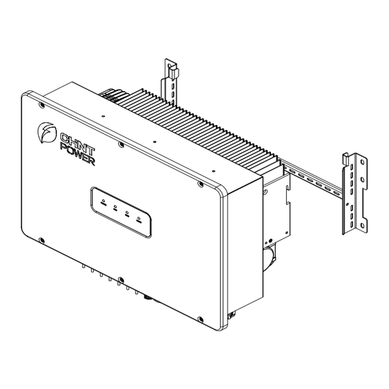
1 Product Dimensions and Components
1.1 Dimemsion
1.2 Main Components
9
1. DC Switch
2. Vent valve
3. MPPT1
4. MPPT2
5. MPPT3
6. MPPT4
7. RS485 interface
8. COM interface
9. AC output
10. Radiator
SCA15/20/25K-T-SA, SCA25K-TM-EU, SCA30/33K-
T-EU inverters are equipped with 3 MPPTs (6 inputs),
SCA36/37.5/40K-T-EU inverters are equipped with 4 MPPTs
(8 inputs). Their installation and electrical connection
NOTICE
pocedures are the same, only 4 MPPT inverters will be taken
as instance. Different points will be introduced seperately.
2 Installation
2.1 Scope of Delivery
H
I
No.
Accessories
Amt
Usage
A
PV Inverter
1
B
Mounting Bracket
1
Hang inverter
6+6
PV DC quick connector
C
DC Input Connector
or
15-33kw: 6 (+) & 6 (-)
8+8
36-40kw: 8 (+) & 8 (-)
D
AC Output Connector
1
Route and protect AC cable
E
WIFI Dongle
1
Communication
2 for mounting bracket;
F
M6X16 screw
3
1 for grounding terminal
Unlock Tool for DC
G
1
Unlock DC connector
Connector
Lock mounting bracket to
H
Expansion Bolt
6
wall
I
RS485 Connector
1
Connect RS485 cable
For quick guidance and
Quick Guide, Warranty Card
2
warranty service
2.2 Installation Environment Requirements
In order to reduce power derating and extend service life, avoid direct
sunlight, rain and snow wherever possible. It is recommended that
inverter is installed under a roof or sunshade as below. However, outdoor
installation is also acceptable, which does not diminish warranty rights.
CAUTION:
R IS K OF BU R NIN G . D O N OT TOUCH!
R IS K OF BU R NIN G . D O N OT TOUCH!
CAUTION:
CAUTION:
R IS K OF BU R NIN G . D O N OT TOUCH!
CAUTION:
AFT ER D ISC O N N EC TIN G AL L SO U R C ES OF
D O NOT RE
S U PPL Y.
DANGER:
B EFO R E OP EN IN G TH E DEVICE , D I SC ONNECT
FR O M G R ID AN D TH E P V GENERATOR. THE
D EV I C E MA Y O N L Y BE O P EN ED BY SE R VI CE
5mi n
MO VE COV ER U NTI L 5 MINU T ES
B EFO R E OP EN IN G TH E DEVICE , D I SC ONNECT
CAUTION:
D EV I C E MA Y O N L Y BE O P EN ED BY SE R VI CE
AFT ER D ISC O N N EC TIN G AL L SO U R C ES OF
MO VE COV ER U NTI L 5 MINU T ES
DANGER:
S U PPL Y.
FR O M G R ID AN D TH E P V GENERATOR. THE
D O NOT RE
5mi n
CAUTION:
D EV I C E MA Y O N L Y BE O P EN ED BY SE R VI CE
FR O M G R ID AN D TH E P V GENERATOR. THE
B EFO R E OP EN IN G TH E DEVICE , D I SC ONNECT
DANGER:
S U PPL Y.
D O NOT RE
AFT ER D ISC O N N EC TIN G AL L SO U R C ES OF
MO VE COV ER U NTI L 5 MINU T ES
5mi n
H AZA R D. THE DC
P ER SO N N EL.
H A Z A R D O U S V O L T A G E AND EN ER GY I N SID E,
D IS C H A R G E BY SE R V I C E PE R SO NN EL BEF O RE
O PE N IN G TH E D EV IC E. E L EC TR IC SH OCK
PH O TO VO LT AIC SY STEM ARE UN G ROU N D ED
CAUTION:
R IS K OF ELECTR
WARNING:
A N D M AY BE EN ER GIZE D.
I C SH OCK - BOTH AC
CON D U C TO RS O F T H IS
AN D DC
H AZA R D. THE DC
O PE N IN G TH E D EV IC E. E L EC TR IC SH OCK
D IS C H A R G E BY SE R V I C E PE R SO NN EL BEF O RE
H A Z A R D O U S V O L T A G E AND EN ER GY I N SID E,
WARNING:
P ER SO N N EL.
CAUTION:
A N D M AY BE EN ER GIZE D.
R IS K OF ELECTR
PH O TO VO LT AIC SY STEM ARE UN G ROU N D ED
I C SH OCK - BOTH AC
CON D U C TO RS O F T H IS
AN D DC
A N D M AY BE EN ER GIZE D.
P ER SO N N EL.
CAUTION:
D IS C H A R G E BY SE R V I C E PE R SO NN EL BEF O RE
O PE N IN G TH E D EV IC E. E L EC TR IC SH OCK
PH O TO VO LT AIC SY STEM ARE UN G ROU N D ED
R IS K OF ELECTR
H AZA R D. THE DC
H A Z A R D O U S V O L T A G E AND EN ER GY I N SID E,
WARNING:
AN D DC
I C SH OCK - BOTH AC
CON D U C TO RS O F T H IS
V OL T AG E S OURC ES A R E TE R MI N ATE D IN SIDE
WARNING - POWER FED FROM
T H IS EQU IP ME N T . E ACH C IRCU IT M U ST B E
D C V O L T A G E T O T H IS E Q UIPME N T.
S ER VIC I NG AN D W HEN T H E PHOTOVO
IN D IVIDUAL L Y D I SC ONNEC T ED B EF O RE
MORE THAN ONE SOURCE
A R R AY IS E XP O SE D T O L IG H T, IT S U PP L IES A
L TAIC
V OL T AG E S OURC ES A R E TE R MI N ATE D IN SIDE
IN D IVIDUAL L Y D I SC ONNEC T ED B EF O RE
T H IS EQU IP ME N T . E ACH C IRCU IT M U ST B E
A R R AY IS E XP O SE D T O L IG H T, IT S U PP L IES A
S ER VIC I NG AN D W HEN T H E PHOTOVO
D C V O L T A G E T O T H IS E Q UIPME N T.
WARNING - POWER FED FROM
MORE THAN ONE SOURCE
L TAIC
WARNING - POWER FED FROM
MORE THAN ONE SOURCE
D C V O L T A G E T O T H IS E Q UIPME N T.
IN D IVIDUAL L Y D I SC ONNEC T ED B EF O RE
T H IS EQU IP ME N T . E ACH C IRCU IT M U ST B E
S ER VIC I NG AN D W HEN T H E PHOTOVO
A R R AY IS E XP O SE D T O L IG H T, IT S U PP L IES A
V OL T AG E S OURC ES A R E TE R MI N ATE D IN SIDE
L TAIC
.E ar th c onnec
c h c u rrent
H igh tou
WARNIN G:
e s s entia l b efor e c o nne c ti n g su p p ly.
ti on
H igh tou
e s s entia l b efor e c o nne c ti n g su p p ly.
c h c u rrent
WARNIN G:
ti on
.E ar th c onnec
WARNIN G:
H igh tou
e s s entia l b efor e c o nne c ti n g su p p ly.
.E ar th c onnec
c h c u rrent
ti on
Avoid direct sunlight
Avoid rain and snow
10
2.3 Recommended Clearances
During planning and installing the inverter, appropriate clearances shown
as below shall be reserved to ensure sufficient ventilation and heat
dissipation. The inverter shall be more than or equal to 300mm distant from
its left or right objects, 500 mm from upper objects, 600mm from lower
objects, and 1000 mm from its front objects. In addition, no objects shall be
put between two inverters to prevent any influences on heat dissipation.
>
>
>
>
2.4 Installation Mode Requirements
(a) Vertically
(b) Tilt backward
(c) Tilt forward
(d) Horizontally
(a) If the location permits, install the inverter vertically.
(b) If the inverer cannot be mounted vertically, it may be tilted backward by
lower than 15 degrees from vertical direction.
(c) Do not mount the inverter leans forward.
(d) Do not mount the inverter horizontally.
(e) Do not mount the inverter upside down.
2.5 Install the Inverter
1. Mark the positions of mounting holes on the mounting structure
according to the size of mounting bracket. Drill six holes with a depth of 65
mm with a Ф12mm drill at the marked positions.
Knock all the six expansion bolts into mounting holes, then remove their
nuts (E), spring washers (D) and flat washers (C), leaving their tubes (B)
and bolts (A) in the wall.
Drill holes on marked position
2. Lead the said six pairs of nuts (E), spring washers (D) and flat washers
(C) through screw holes of mounting brackets and lock them to fasten
mounting brackets onto wall with a torque value of 15 N.m.
R IS K OF BU R NIN G . D O N OT TOUCH!
CAUTION:
B EFO R E OP EN IN G TH E DEVICE , D I SC ONNECT
DANGER:
AFT ER D ISC O N N EC TIN G AL L SO U R C ES OF
MO VE COV ER U NTI L 5 MINU T ES
D O NOT RE
CAUTION:
5mi n
S U PPL Y.
A N D M AY BE EN ER GIZE D.
FR O M G R ID AN D TH E P V GENERATOR. THE
PH O TO VO LT AIC SY STEM ARE UN G ROU N D ED
O PE N IN G TH E D EV IC E. E L EC TR IC SH OCK
H AZA R D. THE DC
D IS C H A R G E BY SE R V I C E PE R SO NN EL BEF O RE
H A Z A R D O U S V O L T A G E AND EN ER GY I N SID E,
WARNING:
P ER SO N N EL.
D EV I C E MA Y O N L Y BE O P EN ED BY SE R VI CE
CON D U C TO RS O F T H IS
CAUTION:
MORE THAN ONE SOURCE
I C SH OCK - BOTH AC
D C V O L T A G E T O T H IS E Q UIPME N T.
WARNING - POWER FED FROM
S ER VIC I NG AN D W HEN T H E PHOTOVO
A R R AY IS E XP O SE D T O L IG H T, IT S U PP L IES A
IN D IVIDUAL L Y D I SC ONNEC T ED B EF O RE
T H IS EQU IP ME N T . E ACH C IRCU IT M U ST B E
V OL T AG E S OURC ES A R E TE R MI N ATE D IN SIDE
R IS K OF ELECTR
L TAIC
AN D DC
e s s entia l b efor e c o nne c ti n g su p p ly.
WARNIN G:
H igh tou
.E ar th c onnec
c h c u rrent
ti on
3. Hang the slots of the inverter onto the hooks of mounting bracket.
>
4. Use two M6X16 screws to fasten inverter on mounting bracket.
Tools required: No.10 hexagon socket wrench, torque value: 5 N.m.
(e) Upside-down
Check that the mounting bracket is properly installed
CAUTION
on the support surface once again before hanging
the inverter on the bracket.
2.6 Installation Check
1. Ensure slots of the inverter is aligned with hooks of mounting bracket.
2. Ensure the inverter is hung steadily on the mounting bracket.
3. Ensure the inverter is locked on the mounting bracket with M6 screws.
3 Electrical Connection
DANGER
3.1 Cable Specifications (Recommended)
Cable
Cable Type
Multi-core cables
AC
specialized for outdoor
Industry common PV
DC
cables (PV1-F)
Cables specialized for
PE
Ground
outdoor
E D C
B
A
4-core cables
RS485
specialized for outdoor
A & B
3.2 Cable Connection
1. AC wiring and Grounding
(1) Insert the four partitions into baffle gaps between different phases.
Install expansion bolt
(2) Remove an appropriate length of the jacket and insulation layer
from the cable. Loosen locking cap from the connector, route the power
cable through the locking cap of the connector and reserve appropriate
wiring length. Insert the exposed core wires into the crimp area of the OT
terminal, wrap the wire crimp area with heat shrink tubing or insulation
tape, and crimp them using hydraulic pliers.
<150mm
(3) Connect ground wire to PE terminal, neutral wire to N terminal, and live
wire to L1, L2, L3 terminal, tighten them using screw driver.
NOTICE
Before performing any electrical connections, ensure
that both DC and AC sides are powered OFF.
Otherwise, fatal injury may be caused by high voltage.
Cable O.D.
Conductor cross-sectional area
(mm)
(mm
2
)
Copper core cable: 16~50
16~38
Aluminum core cable: 35~50
6~7
4~6
NA
≥16
5-6mm
0.21-0.32
L+3 mm
Connect ground wire, neutral wire and live wires
to PE, N, L1/L2/L3 terminals correspondingly. If
connect incorrectly, inverter may work abnormally.
Advertisement

Related Manuals for Chint Power SCA15K-T-SA


Summary of Contents for Chint Power SCA15K-T-SA
- Page 1 Cable O.D. Conductor cross-sectional area Cable Cable Type 2 for mounting bracket; (mm) M6X16 screw Shanghai Chint Power systems Co.,Ltd. 1 for grounding terminal Multi-core cables Copper core cable: 16~50 Unlock Tool for DC 16~38 Official Site: www.chintpower.com specialized for outdoor...
- Page 2 (3) Insert the crimped positive and negative power cables into corresponding (5) After adjusting cable length, insert the connector cover into base slot. 4. Install Wifi communication module as shown below. positive and negative connectors until a "click" sound is heard. Tighten the Pull the two buckles on the two sides of the terminal base to the lugs on Back Smart Link...
Need help?
Do you have a question about the SCA15K-T-SA and is the answer not in the manual?
Questions and answers