Table of Contents
Advertisement
Quick Links
Advertisement
Table of Contents
Troubleshooting

Related Manuals for Chint Power CPS PSW1.5M-1500V


Summary of Contents for Chint Power CPS PSW1.5M-1500V
- Page 1 CPS PSW1.5/3M-1500V Inverter Container User Manual...
-
Page 2: Table Of Contents
Contents 1 About This Manual ..................... 5 1.1 Foreword ..........................5 1.2 Validity............................5 1.3 Content............................. 5 1.4 Target Group ..........................5 1.5 Symbols Explanation ........................ 6 1.6 How to Use this Manual ......................6 1.7 Terminology..........................7 2 Safety Instructions ..................... 8 2.1 Intended Usage ........................... - Page 3 3.2 Inverter Design .......................... 17 3.2.1 Appearance of the Inverters ....................17 3.2.2 Electrical Connections Area....................17 3.3 Power Distribution Box Design ....................17 4 Delivery ......................19 4.1 Scope of Delivery ........................19 4.2 Identifying the Container ......................19 4.3 Checking for Transport Damages ....................
- Page 4 6.4.1 Circuit Diagram ........................35 6.4.2 Cable Specifications ....................... 36 6.5 Ground Connection ........................36 6.6 AC Connection ........................... 37 6.6.1 Safety Notices......................... 37 6.6.2 AC Cable Connection ......................38 6.7 DC Connection........................... 39 6.7.1 Checking before Connection ....................39 6.7.2 DC Cable Connection ......................
- Page 5 9.3.2 Operation information ......................55 9.3.3 Present fault alarm ......................... 55 9.3.4 History ............................ 56 9.3.5 Inverter parameter ......................... 56 9.3.6 System parameter ........................61 9.3.7 Version information ....................... 63 9.3.8 Power dispatching ........................64 10 Container Functions ..................65 10.1 Intelligent Temperature &...
-
Page 6: About This Manual
1 About This Manual Foreword Thank you for purchasing the Inverter Container from Shanghai CHINT Power Systems Co., Ltd. We hope that the device will meet your satisfaction. Your commands and feedbacks on the performance and function of the device are very important for our further improvement. -
Page 7: Symbols Explanation
Familiar with the country/regional standards and specifications Familiar with this manual Symbols Explanation This manual contains important safety and operational instructions that must be accurately understood and respected during the installation and maintenance of the equipment. To ensure the optimum use of this manual, note the following explanations of the symbols used. DANGER: DANGER indicates a hazard with a high level of risk which, if not avoided, will result in death or serious injury. -
Page 8: Terminology
The contents of the manual will be periodically updated or revised due to the product development. It is probably that there are changes of manual in the subsequent inverter edition. The latest manual can be acquired via visiting the web site at www.chintpower.com. Terminology In this manual, the inverter container will be referred to as “container”... -
Page 9: Safety Instructions
2 Safety Instructions 2.1 Intended Usage The container, R & D and manufactured by CPS, is mainly applied to large-and-medium PV power systems. By adopting outdoor standard container design, the container integrates the PV inverters, monitoring units, power distribution units, firefighting system, lighting devices, and security &... -
Page 10: Manual Storage
DANGER: Lethal voltages are present inside the device! Pay attention and follow the warning signs on the device. Respect all safety instructions in this manual and other pertinent documents. DANGER: Electric shock or fire may occur due to the device damage or system fault. ... -
Page 11: Ground Fault Protection
2.2.5 Ground Fault Protection DANGER: If a ground fault occurs to the PV system, some parts that were voltage-free before may contain lethal voltage .Accidental touch may cause serious damage. Make sure there is no system ground fault before operation and take proper protection measures. 2.2.6 Live Line Measurement DANGER: High voltage is present inside the device. -
Page 12: Lcd Parameter Setting
2.2.10 LCD Parameter Setting Certain LCD settable parameters are closely related to the container and internal devices operation, therefore these parameters can only be set after reliable evaluation of the system. WARNING: Improper parameter setting may affect the functionality of the device. ... -
Page 13: Disposal Of Waste
Heating components may exist inside the container. When the device stops, the heating components may still be hot. Wear proper glove when working on them. The inverters and cooling fans inside the container may emit acoustic noise during operation. Wear noise abatement earplug when entering into the container. -
Page 14: Product Description
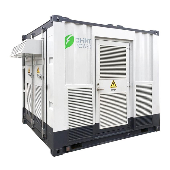
3 Product Description 3.1 Container Design 3.1.1 Container Views View Description Front view Front of the container; a single-door is equipped; the container external grounding point is located on the lower left side. Danger Back view Back of the container; the container external grounding point is located on the lower left side. -
Page 15: Mechanical Parameter
Danger Danger PV Power Station Shanghai Chint Power Systems Co.,Ltd 3.1.2 Mechanical Parameter External dimensions (without the flashings) are shown in figure below. Left view Front view... -
Page 16: Ventilation Design
Devices in the above figure are: Item Device Description Inverter 1 The two inverters are of the same model: CPS SCH1500K; Hereinafter the two inverters will be referred to as #1, #2 Inverter 2 respectively (for 1.5MW container, only one inverter inside) Manhole cover The manhole cover for routine maintenance use. -
Page 17: Flashings Design
The position of 5 cover plates is shown in the following figure by (1) – (5). Danger Danger Danger Danger PV Power Station Shanghai Chint Power Systems Co.,Ltd Left view Back view Right view Figure 3-5 Position of the cover plates... -
Page 18: Inverter Design
3.2 Inverter Design 3.2.1 Appearance of the Inverters Two (or One) CPS SCH1500K inverters are inside of each container. Inverters are core devices inside the container that can convert the DC power to AC power. The appearance of the inverter is shown below. - Page 19 as main and backup power supply to increase the reliability of power supply. The distribution box integrated communication function, the inverters signals and temperature & humidity controller signals can be output from the distribution box to the outside. NOTE: Please confirm the configure of the power distribution box according to the project requirement.
-
Page 20: Delivery
Manufacture date : Rated Output Frequency : Serial Number : Max. AC Output Current : Made in China SHANGHAI CHINT POWER SYSTEMS CO., LTD. PV Power Station Shanghai Chint Power Systems Co.,Ltd Right view Figure 4-1 Location of the container nameplate... - Page 21 preferred. We will provide you with the fast and best service. Examine the contents of the shipment to check if there is anything missing according to the scope of delivery described in 4.1 Scope of Delivery. Check to make sure the container and inner devices are the models placed in your order; ...
-
Page 22: Mechanical Installation
5 Mechanical Installation WARNING: Respect all local standards and requirements during mechanical installation. 5.1 Transport All devices are installed inside the container before delivery. The container can be transported as a whole. If necessary, transport the container by fork lift truck with sufficient load capacity. The container is delivered to the user by a forwarding company. -
Page 23: Hoisting
The hoisting work must be stopped in violent weather days. For example, in strong wind, heavy rain, or thick fog conditions. Please carefully observe the following items: All safety requirements must be met. A professional instructor is needed in the whole hoisting process. ... -
Page 24: Fastening Of Connectors
Figure 5-2 Hoisting from top fittings 5.2.3 Fastening of Connectors Use slings with hooks or U-hooks to hoist the container. The lifting devices should be connected correctly to the container. Lifting Hook U-hook device Connections Insert the hook from inside to Lateral pin of the U-hook should be Notice outside. -
Page 25: Foundation
The forklift used must have sufficient carrying capacity (at least 10 tons). The prong of the forklift used should be at least 1634mm long. Insert the prong into the fork pockets at the bottom of the container. The position of the fork pockets is shown below. -
Page 26: Foundation Requirements
5.4.2 Foundation Requirements WARNING: Pay attention to the heavy weight of the container. Check thoroughly the conditions of the installation site (mainly the geographical and environmental conditions). Then design and construct the foundation. Improper foundation construction may affect the place of the container, open & close of the door and later maintenance of the container. - Page 27 Container front view...
- Page 28 Figure 5-4 Container foundation (recommended) Recommended foundation cross-section area (Length × Width): 3113mm× 2438mm. According to the position and size of the cable inlets/outlets at the bottom of the container, cables must thread through the bottom of the container. During the foundation construction, reserve the trough for AC/DC cables and pre-bury the wire pipes.
-
Page 29: Other Precautions
NOTE: Pre-bury grounding units according to relevant standards of the country/region where the project is located. 5.4.4 Other Precautions NOTICE: A drainage system should be designed on the installation site to prevent the container from being immersed in water during heavy rain falls. NOTICE: Do not plant any trees near the container installation site to prevent the damage of container by tree leaves or stems. -
Page 30: Installation Steps
situations on site. WARNING: After the flashings are installed, the joint between the flashings and the container must be well sealed. NOTICE: The cover plate and the flashings are heavy; therefore, please make sure this procedure is performed by at least two persons. Proceed as follows to install the flashings: Step 1 Remove the cover plate on the upper side of the container left and right sides;... -
Page 31: Electrical Installation
6 Electrical Installation 6.1 Safety Instructions DANGER: High voltage! Electrical hazards! Do not touch the live components of the device. Make sure the AC and DC sides are voltage-free before installation. Never put flammable materials in the vicinity of the inverter. DANGER: If a ground fault occurs to the PV system, some parts that were voltage-free before may contain lethal voltage. -
Page 32: Parts For Cabling
WARNING: Too small bending radius or excessive intertwine may damage the fiber! When selecting fiber as the communication cable, please follow the related requirements of the fiber manufacturer about the min. allowable bending radius. WARNING: Only professional electricians can perform the electrical connection. Professional electricians should meet the related requirements listed in 2 Safety Instructions in this manual. -
Page 33: Copper Wire Connection
NOTICE: Long bolts may affect the insulation and may cause short circuit. Remove the heat-shrinkable tubing between the cable lug and the copper bar if necessary. Poor contact or over-heating may follow if otherwise. NOTE: Clean the connection terminals before cable connection. Do not touch the terminal after cleaning. -
Page 34: Preparation Before Electrical Connections
6.3 Preparation before Electrical Connections Cables inside the container have been connection before delivery. The electrical connection in this chapter is mainly the power cable, communication cable and power supply cable related to the inverter. If the power distribution cabinet has container power supply connection, it is also included inside the electrical connection. -
Page 35: Removal Of The Protective Grid
6.3.3 Removal of the Protective Grid The inverter is equipped with protective grid inside to maintain safe operation. Remove the grid prior to electrical connections. NOTICE: All external cables connect to the connection terminal through the cable entries on the bottom of the inverter. -
Page 36: Container Circuit Diagram And Cable Connection
6.4 Container Circuit Diagram and Cable Connection 6.4.1 Circuit Diagram 3~ 3~ Ethernet 3~ 3~ Ethernet RS485 RS485 RS485 (Optional) (Optional) Communication circuit 1 Communication circuit 2 3~ 3~ Ethernet 3~ 3~ Ethernet RS485 RS485 RS485 (Optional) (Optional) Communication circuit 3 Communication circuit 4 Figure 6-4 Container main circuit diagram Devices in the above figure are:... -
Page 37: Cable Specifications
6.4.2 Cable Specifications Choose cables according to the rules below: All the cables must have sufficient ampacity. The ampacity of the conductor can at least be influenced by environmental conditions, conductor insulation materials, laying, wire materials and cross-sectional areas and etc. ... -
Page 38: Ac Connection
Grounding connection can be divided into two parts, equipotential connection of container internal devices and container external grounding. Figure 6-5 Container ground connection Equipotential connection of container internal devices All devices inside the container should be connected equipotentially. The equipotential connection copper bar is located under of the power distribution box. -
Page 39: Ac Cable Connection
WARNING: If the low-voltage side vector group of the transformer after the inverter is Wye, and the neutral line is present, please ensure the N terminal is floating and not grounded. WARNING: Cables from the two inverters to the LV side of the transformer should be of the same length. -
Page 40: Dc Connection
Step 8 Check to ensure the connection is secure. Finish the AC cable connection of all two inverters according to the above steps. Figure 6-6 Location of AC output and copper bar Figure 6-7 Dimensions of holes on AC copper bars (mm) 6.7 DC Connection 6.7.1 Checking before Connection Check the following items before cable connections. -
Page 41: Dc Cable Connection
6.7.2 DC Cable Connection Proceed as follows to connect the DC cables: Step 1 Make sure the switch upstream of the combiner box is in the OFF position. Step 2 Strip off the insulation cover of the cable with a tripped length of 5mm longer than the depth of the cable lug. -
Page 42: Auxiliary Power And Dry Contact Connection
(b) Dimensions of holes on DC copper bar for Aluminum cable (mm) Figure 6-8 Dimensions of holes on DC copper bar (mm) Finish the DC cable connection of all two inverters according to the above steps. Connect DC positive and negative cables to positive and negative copper bars correspondingly. The positions of DC input positive and negative copper bars are shown as in Figure 6-9. -
Page 43: Communication Connection
Figure 6-10 Auxiliary power switch and dry contact connection (1) No. 1 and 2 points of the terminal ① can be connected to the AC 220V as the working power supply of the inverter. Using auxiliary power switch: switch the auxiliary power to “OUTSIDE” if need the external working power. -
Page 44: External 1Phase Or 3-Phase Container Power Supply (Optional)
Figure 6-12 Location of communication ports (2) Inverter communication is directly connected with 485 bus through RS485-1 or RS485-2 port on the inverter. (3) To remotely monitor a number of inverters Connect the RS485-2 port of one inverter with the RS485-1 port of another one in cascade, and then connect the last inverter to the data logger through the RS485 communication bus cable. -
Page 45: Commissioning
7 Commissioning 7.1 Safety Instructions DANGER: High voltage! Electric shock! Wear proper protection equipment before all operations on the device. Do not touch the live terminals or conductors. Respect all safety instructions inside the device and in this manual. ... -
Page 46: Checking Before Commissioning
NOTICE: All operation during commissioning must be performed by qualified personnel only. NOTE: Commission the device when it is sunny and the environmental conditions are stable to ensure the successful commissioning. 7.3 Checking before Commissioning 7.3.1 Checking the Cable Connection ... -
Page 47: Checking Grid Voltage
NOTE: The PV field circuit fault (module fault or module numbers deviation in certain array), cable damages or connection looseness may cause the voltage deviation exceeding 3% at stable environmental conditions. Record the environmental parameters (temperature and radiation intensity, etc.). ... -
Page 48: Lcd Parameter Setting
Step 8 Disconnect the AC and DC switches of inverter #1. Step 9 Perform step 3-8 to inverter #2. Make sure all two inverters can operate normally. Step 10 Set the inverter output power to the default value through LCD display. Step 11 Close the AC and DC switches of the two inverters (The number of DC input is determined according to the actual situation). -
Page 49: Operation
8 Operation 8.1 Check before start-up Check and make sure the following items are ready before start-up: Make sure that all the connection cables are well connected without damage or cracks, and all the screws are fastened in place; Make sure that AC/DC side voltage meets the requirement of the inverter, and make sure there is no risk of over-voltage;... -
Page 50: Operation Mode
Figure 8-1 Select grid regulation NOTE: CHINT is the reserved customized grid regulation. NOTE: Please confirm the grid regulation with your local electricity company first. After selecting the grid regulation, the inverter will start up automatically. If the grid regulation needs to be changed, please refer to “9.3.5 Inverter Parameter”. 8.3 Operation mode The inverter has 4 operation modes. - Page 51 set value after the inverter is normally connected to the grid, or when the AC power grid fails, the inverter will automatically exit the "operation" mode and stop Feed the grid. (b) Manual shut-down: If service personnel need to maintain or repair the inverter, please take the following steps: (1) Click “Inverter Parameter”...
-
Page 52: Grid-Tied Power Generation
Fail Fail Off line Off line Off line Figure 8-3 Discharging failure of the inverter Note: Refer to the first start-up procedure of the inverter after the maintenance. INSTRUCTION: The command of de-energy will be ineffective if the inverter is being energized. Wait and execute the command until the process of de-energy is completed. - Page 53 be eliminated until the system is restarted; if service personnel need to maintain the inverter, please refer to “Maintenance Shutdown”. The system can be disconnected to stop working when CPS SCH1500K has the failures such as DC overvoltage, overcurrent, DC input reverse connection or 3-phase output AC interruption (when the internal power mode is selected), or external connection 220VAC interruption (if auxiliary powering mode is selected).
-
Page 54: User Interface
9 User Interface 9.1 Description of LCD panel The LCD panel of CPS SCH1500K is mainly composed of LCD screen, LED lights and buzzer. The indications of the lights refer to Table 9-1. Table 9-1 LED lights and indications LED Light Name Status Indication... -
Page 55: Home Page
the system is energized, and then enters the home page after 3s. Figure 9-1 System startup There are seven first-level submenus in display interfaces altogether, including home page, operation information, present alarm, history, inverter parameter, system parameter and version information. First level submenu labels are available at the top ends of most of interfaces, and the system can enter the corresponding submenus by clicking the labs. -
Page 56: Operation Information
9.3.2 Operation information Click “Operation Information” for checking more operation information. The submenu has four pages and supports page turning check. The first page displays the operation information on the AC side; The second page displays the on-line states of all modules as well as PV voltages, PV currents and DC powers;... -
Page 57: History
9.3.4 History Click “History” to enter a history menu. There are 3 submenus under this menu, including “Fault Record”, “Power Curve” and “Electric Energy Production Curve”. (1) Under the “Fault Record” menu, 4000 recent faults together with fault occurrence and clearance time records can be seen;... - Page 58 inquired. Whether modules are on-line is shown as the table below: Table 9-2 Complete machine Module 1 is on-line Module 1 is selected Module on-line NOTICE: CPS SCH1500K has 2 modules. The number of on-line modules of the inverter is correct or not should be confirmed before inverter startup.
- Page 59 Protection time for upper limit of Class I grid 0.05 655.34 0.00 voltage I (s) Lower limit of Class I grid voltage I (%) 50.0 100.0 Protection time for lower limit of Class I grid 0.10 655.34 0.00 voltage I (s) Grid overvoltage recovery point (%) 108.0 120.0...
- Page 60 HVRT trigger voltage (%) 115.0 135.0 110.0 Power recovery step size (kW/s) 250.00 327.67 Active derating control Default Active derating (%) 110.0 110.0 Active step size (kW/s) 100.00 327.67 0.00 Overfrequency derating setting Overfrequency derating trigger frequency 50.2 55.00 50.00 Overfrequency derating slope (%/Hz) 40.0 100.0...
- Page 61 In case of modification of the equipment protection parameters, the "red dot" found before the name of the protection parameters indicates that in the current on-line modules, the protection parameters are not entirely consistent with each other, as shown in Figure 9-5 (red dot). Figure 9-5 shows that there is a red dot before "power grid undervoltage recovery point", indicating that in the current on-line modules, the "power grid undervoltage recovery points"...
-
Page 62: System Parameter
2016-02-05 10:21:32 FRI Figure 9-7 Order parameters In this menu you can view the on and off status, and perform startup, shutdown, forced restart, factory reset, rapid discharge and fault history clearing, operation of PV curve scanning, bus capacitance capacity prediction and so on. If the inverter fails to meet the startup conditions, even if you select "Start Up", the inverter will not step into power generation operation state, but the standby state. - Page 63 (1) “System clock”: click on any number of the date and time to set the correct system time (very important parameter! Affecting the operation of the information recording), and then click on the "Synch" button to synchronize the time of the inverter. (2) "Language": English and Chinese.
-
Page 64: Version Information
2000 5 Figure 9-10 Other Configuration In the inverter, the AC meter function and PID function are selected. Under this interface, these two functions can be configured. 9.3.7 Version information In this menu, touch screen, communication board, DSP software version, serial number of the equipment, and the contact information of the manufacturer are listed. -
Page 65: Power Dispatching
offline online offline 1.03 0.00 0.00 offline online offline 0.00 1.03 0.00 offline offline offline 0.00 1.03 0.00 offline offline offline 0.00 1.03 0.00 offline offline offline 0.00 0.00 1.03 Figure 9-12 List of module software version 9.3.8 Power dispatching Inverter "active dispatching", "reactive dispatching"... -
Page 66: Container Functions
10 Container Functions 10.1 Intelligent Temperature & Humidity Control Technology The inside of Container has intelligent temperature & humidity control device. When the temperature & humidity exceeds the set value, the intelligent temperature & humidity control device will open the fan, so that the temperature & humidity dropped below the set value. 10.2 Firefighting 10.2.1 General Introduction Respect the national and local firefighting rules and regulations. -
Page 67: Troubleshooting
11 Troubleshooting 11.1 Safety Instructions DANGER: Lethal voltages are present inside the container when a fault occurs. Only qualified personnel can perform the troubleshooting described in this chapter. Qualified means that the operator has received professional training on devices troubleshooting. ... -
Page 68: Fault And Troubleshooting On The Lcd Screen
11.3 Fault and Troubleshooting on the LCD screen Before you contact our after-sales service center, you are able to find most faults and solutions in Table 11-1 for troubleshooting. There are three categories of fault alert statuses: Warn, Protect and Fault. - Page 69 1. The fan is blocked; 1. Observe for 5 minutes to see 2. The power supply whether the alarm circuit of the fan will be eliminated goes wrong; AC fan (invisible automatically; from the outside) 3. The state test 3. Warn 0020 2.
- Page 70 1. Make sure the SVG device is ordered and correctly installed; 2. Observe for 5 SVG charging circuit minutes to see 7. Warn0060 Internal warn is abnormal whether the alarm will be eliminated automatically; 3. Contact our after-sales service center 1.
- Page 71 1. Observe for 5 minutes to see whether the alarm DC breaker will be eliminated 11. Warn0010 Internal warn automatically; abnormal 2. Contact our after-sales service center 1. Observe for 5 minutes to see whether the alarm DC breaker will be eliminated 12.
- Page 72 1. Observe for 10 minutes to see whether the alarm will be eliminated 1. Grid voltage is automatically; abnormal; 2. Check whether the 2. The grid halts; grid voltage is Grid voltage exceeds 3. The connection within the range; 2. Abnormal grid the specified range;...
- Page 73 1. Observe for 30 minutes to see whether the alarm will be eliminated automatically; 2. Check whether the PV voltage 1. The PV voltage is exceeds the too high; specified range; 4. Excessively high PV voltage exceeds PV voltage the specified value 2.
- Page 74 1. The AC contactor 1. Contact our is damaged after-sales service 7. Abnormal AC AC contactor is center contactor abnormal 2. The inverter has internal faults 1. Check that the emergency stop button is pressed; 1. The emergency if yes, please reset stop button is the emergency 8.
- Page 75 1. Restart the inverter if there is no other problem; The inverter has Unspecified internal 2. Record protect Fault 0010~0160 internal faults inverter faults code; 3. Contact our after-sales service center Fault Replace the fuse on GFDI board; 1. The fuse on the *Grounding fault 2.
-
Page 76: Routine Maintenance
12 Routine Maintenance 12.1 Safety Instructions Due to the effect of ambient temperature, humidity, dust and vibration, the container and the inner components will be aging and worn out. To ensure the system safety and maintain the efficiency of the container, it is necessary to carry out routine and periodic maintenance. All measures, which can help the container in good working conditions, are within the maintenance scope. -
Page 77: Maintenance
12.2 Maintenance 12.2.1 Introduction With IP54 protection degree, the container can be installed outdoors. Harsh environment condition or long-time operation, however, may cause age and damage of the container. Check and maintain the container periodically and replace the aged components can effectively enlarge the service life and increase the device performance inside the container. - Page 78 Item Method Interval External Make correction immediately once the following Every quarter checking items are found: Check if there is flammable materials on top of and around the container; and if there are other factors that may impair the system operation ; ...
- Page 79 terminals is strip-off. Air inlet/outlet Check if the air inlet filter and ventilation ducts Every six months or of the container and internal devices are maintain according to normal; real situation Clean or replace the filter. Check the running state of the fan inside the Every six months or container;...
-
Page 80: Container Filter Checking And Cleaning
12.2.3 Container filter checking and cleaning NOTE: It is recommended to check and clean the container filter at least every six months. The maintenance interval should be shortened to once every three months or shorter if the dust deposition is heavy. The air inlets located on around of the container are entrances of cool air. -
Page 81: Replacement Of The Electrical Components
12.2.5 Replacement of the electrical components WARNING: The electrical components inside the container must be replaced by the same components from the same manufacturer and with the same model number. The model number can be acquired from the marking of the container or the component itself. -
Page 82: Appendix
13 Appendix 13.1 Container System Parameter Model Name CPS PSW1.5M-1500V CPS PSW3M-1500V DC Input Max. PV Power 2250kWp 4500kWp Max. DC Input Voltage 1500Vdc Working DC Input Voltage Range 880-1500Vdc Start-up DC Input Voltage 940Vdc MPPT Voltage Range 900-1300Vdc Number of MPPT Tracker Number of DC Input Max. -
Page 83: Exclusion Of Liability
Unforeseen calamity or force majeure 13.3 About Us Shanghai Chint Power Systems is a solar power system solution provider, designing, manufacturing, and supplying high reliability 1kW~3MW PV inverters and power solutions for customers. An international senior management team, experienced and solid research and... -
Page 84: Contact Information
Chint Power System's brand in the field of renewable energy. 13.4 Contact Information Should you have any questions or queries about this product, please contact us through the following information. We will be more than happy to assist you! Company: SHANGHAI CHINT POWER SYSTEMS CO., LTD.
Need help?
Do you have a question about the CPS PSW1.5M-1500V and is the answer not in the manual?
Questions and answers