
Related Manuals for Chint Power CPS Series


Summary of Contents for Chint Power CPS Series
- Page 1 CPS Series Photovoltaic Grid Connection Inverter CPS SC100KT Installation and Operation Manual Shanghai CHINT Power Systems Co., Ltd.
-
Page 2: Table Of Contents
Table of Contents Chapter 1 Safety Instructions ..........1 Chapter 2 Overview............3 2.1 Photovoltaic system for grid connection ....3 2.2 Inverter circuit structure ........4 2.3 Illustration for front and top views......5 Chapter 3 Installation ............3.1 Basic requirements..........6 3.2 Mechanical installation ........ - Page 3 Chapter 5 Human Machine Interface .......28 5.1 Description of LCD display ......28 5.2 Operation State ..........29 5.3 Interface and menu functions ......30 5.3.1 Interface types ........30 5.3.2 Main operation interface......32 5.3.3 Operation information......33 5.3.4 Present fault..........34 5.3.5 History.............34 5.3.6 System setup ..........36 5.3.7 System protection parameter setup ..37 Chapter 6 Technical Data ..........40...
-
Page 4: Chapter 1 Safety Instructions
Chapter 1 Safety Instructions Please read this manual carefully before installation. CPS reserves have the right not to guarantee the quality for equipment damage if the user fails to install the equipment as per the instructions in this manual. Electric shock hazard: Make sure that all DC and AC are isolated from the equipment to prevent electric shock hazard during equipment maintenance or installation. - Page 5 switched off. Therefore, equipment shall not be serviced or operated until 60 minutes after all inputs are switched off. For grid connection only! This inverter is specially designed for directly connecting AC power to public power grid. Do not connect the AC output of this equipment directly to private AC power equipment.
-
Page 6: Chapter 2 Overview
Chapter 2 Overview 2.1 Photovoltaic system for grid connection CPS SC100KT grid connection photovoltaic inverter applies to all kinds of commercial roof grid connected system or grid connected power station system. Normally, the system consists of solar cell modules, DC power distribution unit, grid connection inverter and AC power distribution unit (Figure 2-1). -
Page 7: Inverter Circuit Structure
2.2 Inverter circuit structure The basic schematic diagram of CPS SC100KT inverter is shown in Figure 2-2. The output of solar cells first passes through DC switch and DC EMI wave filter circuit. The inverter then converts DC voltage to 3-phase AC voltage. The output wave filter will remove high frequency component, and is connected to LV grid through industrial frequency transformer step-up and isolation, AC contactor, AC EMI... -
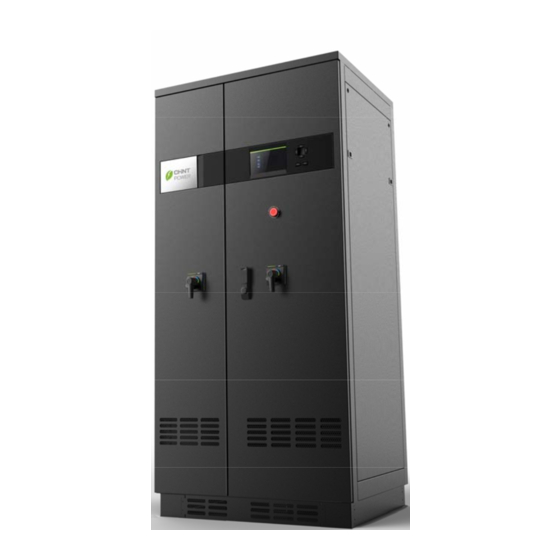
Page 8: Illustration For Front And Top Views
2.3 Illustration for front and top views Figure 2-3 Appearance sketch Description of main items (shown in Figure 2-3): 1、Mounting plate for lifting ring 2、Display panel (with LED indication and LCD Display) 3、Operation keys (Up, Down, Left, Right, ESC, ENT) 4、Emergency switch button 5、Switch on DC side 6、Lock... -
Page 9: Chapter 3 Installation
Chapter 3 Installation 3.1 Basic requirements The protection level of CPS SC100KT photovoltaic inverter is IP20. Do not install it in a humid environment. Check and make sure that the ambient temperature of the installation location is -20 C ~+65C; ... - Page 10 Figure 3-1 Sketch of dimensions Figure 3-2 Sketch of foundation installation dimensions (2) Requirements on inverter installation: Front door: A 560mm space should be reserved to ensure that the front door can be opened and closed freely. Back: A 600mm space should be reserved to allow for maintenance.
- Page 11 The weight of the inverter is approximately 900kg. Make sure that the mounting place can bear the weight. Two approaches are recommended to lift the machine, i.e. lifting with a crane and lifting with a hydraulic forklift: Lifting with a crane: Bolt the 4 lifting lugs at the 4 corners of the top the machine.
-
Page 12: Electrical Installation
back baffle front baffle Figure 3-4 Sketch of handling by forklift 3.3 Electrical installation Open the front door of the machine. Proceed as shown in Figure 3-5. 1、Turn the handle bar of the latch at DC side to right toward horizontal position. 2、Turn the handle bar of the latch at AC side to right toward horizontal position. -
Page 13: Dc Connection
Figure3-5 Sketch of opening front door 4、 Remove the transparent Plexiglas cover at the bottom of the machine and install the external wires after the front door is open (as shown in Figure 3-6). All external wires must penetrate the wire holes at the bottom of the machine Figure 3-6 Sketch of external wiring 3.3.1 DC connection... - Page 14 (b) Ensure that the polarity of DC input is correct, i.e. the positive pole of photovoltaic module is connected to the positive pole of the inverter DC input, and the negative pole of photovoltaic module is connected to the negative pole of the inverter’s DC input;...
-
Page 15: Ac Connection
Figure 3-7 DC input wiring 3.3.2 AC connection Connect the AC output of photovoltaic inverter to the AC cabinet or the power grid through AC output cables and grounding wires: (1) Use the recommended AC output cables, L1 (Line 1)、L2 (Line 2)、L3 (Line 3) :70mm ;... -
Page 16: Communication Connection
Figure 3-8 AC output wiring (3) Connect power grid A to terminal L1. Connect power grid B to terminal L2. Connect power grid C to terminal L3. Connect power grid PE cable to terminal G. (4) Tighten terminals L1, L2, L3 and PE. Make sure that all cables are tightened properly. - Page 17 (1) Terminal 1 is connected to RS485+. Terminal 2 is connected to RS485-. Twisted pair cable is connected to 485 busbar. (2) Terminal 3 and terminal 4 can be connected to an external 380V power supply and used as power supply of the inverter.
-
Page 18: Chapter 4 Operation
Chapter 4 Operation 4.1 Start-up and shut-down 4.1.1 Start-up Check and make sure that input and output cables are connected correctly. Close the DC circuit breaker at PV side then close the AC circuit breaker at power grid side. Manual start-up: Manual start-up is required after initial installation or manual (failure) shut-down. -
Page 19: Operation Mode
or shutdown by human is required. (1) Move the cursor from the main operation interface to “4 Setting”. Click the ENTER key and enter submenu “1 ON/OFF”. The inverter is shut down after moving the cursor to “OFF” and pressing the ENTER key. (2) Press the emergency button on the panel to shut down the inverter in case of emergencies. - Page 20 (2) Normal operation, as shown in Figure 4-2: Figure 4-2 Default indication interface for normal operation In this mode, the inverter converts the power generated by solar cell panels to AC continuously and feeds in the power grid. (3) Standby mode, as shown in Figure 4-3: The inverter will enter standby mode when the voltage of PV panel is too low or output power cannot meet the startup condition.
-
Page 21: Grid Connection And Power Generation
(4) Failure mode, as shown in Figure 4-4: The inverter will disconnect from the power grid and enter failure mode when photovoltaic power generation system fails. Check the specific cause through LCD “Troubleshooting” and eliminate the failure with the instructions. Figure 4-4 Fault indication interface Warning Disconnect the AC circuit breaker at the power grid... -
Page 22: Fault Shutdown
time, it will also check whether photovoltaic array has sufficient energy. The inverter will enter grid connection and power generation mode when everything is ready. The inverter will maximize the photovoltaic array output power in MPPT (Maximum Power Point Tracking) during the grid connection and power generation. - Page 23 Table 4-1 Troubleshooting Table Alarm/Prote-cti Definition Possible causes Recommended solutions on/Failure 1、Check status of PV 1、Forget to close switch; PV switch; 2、Check whether PV 2、 PV is connected Indicate that PV cabling is correct; 1、PV reversely; switch is in 3、Check whether sunlight BrkerOpen 3、Input current is disconnection state...
- Page 24 1、Observe for 5 1、Fan is minutes and see blocked; whether the inverter 2、 Power supply can eliminate this circuit of the fan alarm automatically; The visible has problem; 2、Check for foreign fan from 3、 Fan state test 4、 matters on fan blades outside is circuit has ExtFanErr...
- Page 25 1、 Observe for 10 minutes and see whether the inverter can 1、Grid voltage is eliminate this alarm abnormal; automatically; Grid voltage Power grid outage 2、Check whether the grid exceeds the 2、Connecting voltage is within the specified 2、 cable between the specified range;...
- Page 26 1、PV positive pole and negative pole 1、Check whether positive PV panel is are connected pole and negative pole are 5、PV.Reverse connected reversely; connected reversely; reversely 2、 2、Contact after-sales Failure inside the service personnel inverter 1、Excessive parasitic 1、Observe for 10 minutes capacitance on PV and see whether the inverter panel due to...
- Page 27 1、Check whether emergency 1、Emergency button is pressed. Reset the 10、 Emergency button is pressed emergency button if it is pressed. EmergencyST button is closed 2、Failure inside 2、Contact after-sales service the inverter personnel if the problem persists after the emergency button is reset 1、The inverter can be forced restarted only once if it is required Serious failure...
-
Page 28: Chapter 5 Human Machine Interface
Chapter 5 Human Machine Interface 5.1 Description of LCD display CPS SC100KT display mainly consists of LCD screen, LED indicator lights, buzzer and 6 keys. Meanings of indicator lights are shown in Table 5-1 and functions of the keys are shown in Table 5-2. Table 5-1 LED Indication Description State... -
Page 29: Operation State
Table 5-2 Definitions of the keys Description Definition of function Escape ESC( Back/end/mute Enter Confirm entering the ) ENTER( menu/confirm set point PAGEUP( ) Page up in selection menu PAGEDOWN Down Page down in selection menu ( ) ADD( ) Left +1 when setting parameters DEC(... -
Page 30: Interface And Menu Functions
occurs. “FAULT” will not light up if the grid is normal. The buzzer will sound alarms if a failure (including power grid abnormality) occurs. 5.3 Interface and menu functions Users may can perform the corresponding operations of the 6 function keys witch the indications of the LCD display. 5.3.1 Interface types (1) The system starts with the company logo as in Figure 5-1 once the system is energized. - Page 31 Figure 5-3 Default display interface for normal operation Figure 5-4 Inverter system in standby mode Figure 5-5 Failure indication interface LCD screen will display different mode interfaces based on the operation modes of the inverter. There are four operation modes: startup self-checking mode (as shown in Figure 5-2), normal operation mode (as shown in Figure 5-3), stand-by mode (as shown in Figure 5-4) and fault mode (as shown in Figure 5-5).
-
Page 32: Main Operation Interface
The default indication interface mainly indicates PV voltage, PV current, grid voltage, generation power and time information under normal operation. LCD screen jumps to failure indication interface and display the present failure information automatically when the inverter is in fault mode. 5.3.2 Main operation interface LCD screen will indicate “default indication interface”... -
Page 33: Operation Information
5.3.3 Operation information When the cursor moves to “1 OP. Info” in the main interface, press ENTER to enter the operation information menu as shown in Figure 5-7. Check the information by pressing PAGEUP and PAGEDOWN. Return to the previous menu and enter the main operation interface by pressing ESC. -
Page 34: Present Fault
5.3.4 Present fault As described above, fault currently occur which have not recovered are indicated under this menu during the operation of the inverter apart from sound and light alarms. In the main interface, move the cursor to “2 Alarm” and press ENTER to enter the present fault menu and check the present failure information, as shown in Figure 5-8. - Page 35 (2) In “2 OP. Recd” menu, check the history of operation data of the latest 21 days. Data include all variables in “1 OP. Info” under the main interface menu. The users can select and enter the “Operation record” menu and enter the retraceable days (For example, enter 21, if the current date is December 15th , then it will indicate the operation information of 21 days before that date ,that is, November...
-
Page 36: System Setup
5.3.6 System setup Move the cursor to “4 Setting” in the main interface. Press ENTER to enter the setup menu of the curent system parameters and set up the relevant parameters, as shown in Figure 5-10. There are 5 submenus in the system setup menu: “1 ON/OFF”, “2 Language”, “3 Buzzer”, “4 Time”... -
Page 37: System Protection Parameter Setup
(These parameters are important and will be used in history information). (5) Set up 485 communication parameters with “5 ComPara” menu. → ON ON State 中文 → English 1 ON/OFF 2 Language 3 Buzzer 4 Setting →4 Time English Ver. 5 CommPara KeyBeep Enable... - Page 38 (1) Set up the system protection parameters with “1 SysPara” menu. The types of protection parameters are shown in Table 5-3. (2) “2 Restart” menu. If an internal failure shutdown indicates that a hard failure has occurred inside the inverter, the user may perform a force restart once under this the menu if the user needs to restart the inverter.
- Page 39 GridV.Max(V) GridF.Max(HZ) PowerDerating(%) → 450 → 50.2 → 90 GridV.Min(V) GridF.Min(HZ) ReactiveComp(%) 47.5 →1 SysPara. Pls Input Pwd **** 2 Restart Are You Sure? 3 Recover 4 ClrErrRecd Restarting... Are You Sure? PwdError Pls Input Again Success! Recovering.. Fault Operating Failure!...
-
Page 40: Chapter 6 Technical Data
Chapter 6 Technical Data CPS SC100KT DC Input Max. DC Voltage* 880Vdc MPPT Voltage Range 430~820Vdc Max. DC Power 110KWp Max. Input Current 240A Max. DC Short Circuit 300A Max. Number of Strings AC Output Output Power 100KW Norminal Output Voltage 400Vac 3 phase Grid Voltage 320~460Vac... - Page 41 Forced cooling/RPM Cooling regulated fan Stand by consumption <50W Display and communication Communication RS485 Display Mechanical parameters WxDxH(mm) 920x725x1900 Weight (kg) *Note: Exceeding the rated voltage value shown in “Max. DC voltage” may cause permanent damage to the equipment. Chapter 6 Technical Data...
-
Page 42: Chapter 7 Quality Assurance
Chapter 7 Quality Assurance 7.1 Warranty The warranty policy of this product is specified in a contract; otherwise the warranty period is 24 month after the date of installation. 7.2 Disclaimer 1、Damages caused during transportation; 2 、 Operating in an environment that is out the specification of the product;... - Page 43 Please do not hesitate to contact us if you have any questions regarding CPS SC100KT photovoltaic grid connection inverter. CPS is glad to provide service the best for you at any time. Chapter 7 Quality Assurance...
Need help?
Do you have a question about the CPS Series and is the answer not in the manual?
Questions and answers