
Related Manuals for Chint Power CPS SCE4


Summary of Contents for Chint Power CPS SCE4
- Page 1 CPS SCE Series Grid-tied PV Inverter CPS SCE4/5/6/7KTL-O/US Installation and Operation Manual Version: 1.1...
- Page 2 Web: www.chintpower.com/na Suite 102 Richardson, Texas Email: americasales@chintpower.com Zip Code: 75081 Service Hotline: 855-584-7168 SHANGHAI CHINT POWER SYSTEMS AMERICA CO., LTD. All rights reserved. Specifications and designs included in this manual are subject to change without notice. CHINT POWER 2013/06-MKT...
-
Page 3: Table Of Contents
Contents Before You Start… ------------------------------------------------------------------------------------------ 1 Important Safety Notification --------------------------------------------------------------------------- 2 1. Introduction ------------------------------------------------------------------------------------------------ 4 2. Limited Warranty ----------------------------------------------------------------------------------------- 5 3. Features Overview -------------------------------------------------------------------------------------- 6 4. Product Overview ---------------------------------------------------------------------------------------- 7 4.1 Introduction of Grid-tied PV system ---------------------------------------------------------- 7 4.2 Introduction of CPS Grid-tied PV Inverter -------------------------------------------------- 8 4.3 Dimensions and Weight ------------------------------------------------------------------------- 9 4.4 Control and Display Overview --------------------------------------------------------------- 10 4.5 LED Indicators ----------------------------------------------------------------------------------- 11... -
Page 4: Before You Start
Before You Start… This manual contains important information regarding installation and safe operation of this unit. Be sure to read this manual carefully before using. Thanks for choosing CPS Grid-tied PV Inverter (referred to in this manual as “PV Inverter”, or simply “Inverter”). This PV Inverter is a highly reliable product due to its innovative design and perfect quality control. -
Page 5: Important Safety Notification
Important Safety Notification General This user manual contains important instructions and notifications that must be followed during installation and maintenance of the CPS grid-tied PV Inverter. The CPS grid-tied PV Inverter is a well-designed product through strict tests to meet international safety requirements, but as an electrical and electronic equipment, certain precautions must be observed during the installation and operation of the PV Inverter. - Page 6 Safety Symbols ELECTRIC SHOCK Electric shock indicates a potential risk of electric shock if not avoided. WARNING Warning indicates a potentially hazardous situation that could result in death or serious injury if not avoided. CAUTION Caution indicates a hazardous situation that could result in minor injury if not avoided.
-
Page 7: Introduction
1. Introduction This manual describes all the information needed to install and operate the following PV Inverter Models: CPS SCE4KTL-O/US, CPS SCE5KTL-O/US, CPS SCE6KTL-O/US, and CPS SCE7KTL-O/US IMPORTANT In order to avoid problems during the installation, it is recommended to read the entire user manual before any installation procedures. -
Page 8: Limited Warranty
ELECTRIC SHOCK Risk of electric shock from energy stored in capacitors. Do not remove the cover until three minutes after disconnecting all sources of power supply and the service should be done by qualified personnel. 2. Limited Warranty The warranty policy of this product is specified in the contract; otherwise, the warranty period is 10 years. -
Page 9: Features Overview
3. Features Overview Max. energy yield CEC efficiency of 97% Transformer-less Design Field selectable voltage out: 208/240/277 Vac Wide MPPT voltage operating range: 105-500V Integrated NEC compliant wire raceway Integrated PV system AC / DC disconnect switch ... -
Page 10: Product Overview
4. Product Overview 4.1 Introduction of Grid-tied PV system The grid-tied PV system is mainly composed of four parts: PV modules, DC distribution unit, grid-tied PV inverter and AC distribution unit. When the PV modules are exposed to sufficient irradiation, they will generate DC power. First, the DC will be fed to the PV Inverter (via DC distribution unit). -
Page 11: Introduction Of Cps Grid-Tied Pv Inverter
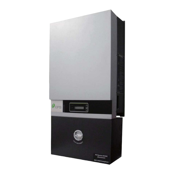
4.2 Introduction of CPS Grid-tied PV Inverter CPS grid-tied PV Inverter converts direct current (DC) power generated by a PV panel into alternating current (AC), which is compatible with the local electric distribution network, also called the public grid. The CPS grid-tied PV Inverter is designed with a transformer-less topology. -
Page 12: Dimensions And Weight
4.3 Dimensions and Weight Figure 4.3.1: Dimensions of PV Inverter Table 4.3.1 Product weight in the package Inverter Model SCE4KTL-O/US SCE5KTL-O/US SCE6KTL-O/US SCE7KTL-O/US Net Weight (lbs) 90.4 101.4 101.4 Copyright CPS America Co., Ltd. Page 9... -
Page 13: Control And Display Overview
4.4 Control and Display Overview Figure 4.4.1: Overview of CPS PV Inverter A. LCD Display LCD screen displays all measured values and parameters. B. LED Indicators There are three indicators used to indicate the operating status. C. Control Buttons They are three control buttons available to switch between each display menu and configure the settings for the LCD. -
Page 14: Led Indicators
4.5 LED Indicators CPS grid-tied PV Inverter has three built-in LED indicators which will provide information of the operational status: Figure 4.5.1: LED Indicators Power-On LED Indicator It is a green LED indicator which will light up in green when the feed-in DC voltage from PV array reaches the minimum operating voltage for the PV Inverter. -
Page 15: Control Buttons And Lcd Displays
4.6 Control Buttons and LCD Displays CPS grid-tied PV Inverters are equipped with three control buttons which could be used to switch between display menus. Figure 4.6.1: Control buttons and LCD displays A) Up Control Button The up control button is used to advance the display menu or move the cursor up B) Enter Control Button The enter control button is used to configure the settings such as... -
Page 16: Installation Of Pv Inverter
5. Installation of PV Inverter 5.1 Open the package The product package contains the following items (Table 5.1.1): Q’ty Item Note (1) PV-Inverter Photovoltaic Inverter (2) Mounting Bracket Upon which Inverter be hang and mounted onto a wall (3) Accessory Box Contains all necessary accessories (Table 5.1.2) Note: Please keep the package box in case of need for sending the product for repair service. -
Page 17: Visually Check The Pv Inverter
5.2 Visually check the PV Inverter It is important to check the PV Inverter for any visible damage, including the LCD screen. If there are visible damages can be found, please contact the dealer or supplier immediately. WARNING Due to the weight of the inverter, it is recommended at least 2 people lift the PV Inverter from the packing and also for the mounting the PV Inverter on the wall. -
Page 18: Identify The Pv Inverter
5.3 Identify the PV Inverter The structure of the CPS grid-tied PV Inverter can be divided into two parts, main housing and wiring box shown in figure 5.3.1. The main housing contains the electrical components that are used for power conversion and the wiring box contains the electrical components that are used as the connection points for DC input voltage and AC output voltage as required by the NEC. - Page 19 Figure 5.3.2: Main Housing Name Plate A warning label plate is located in the left-hand side of PV Inverter as indicated in figure 5.3.4. This warning label is used to indicate all important notices that shall be known. When you are dealing with the general utility system and DC generator, read and follow all notifications from the warning label as a reminder in order to prevent any electric shock that can happen during the configuration period.
-
Page 20: Mount The Pv Inverter
5.4 Mount the PV Inverter Figure 5.4.1: Required Dimension Select a dry location, out of direct sunlight with ambient temperature between -20 and 45° C. IMPORTANT It is important not to install the CPS grid-tied PV Inverter under direct sunlight, because the exposure of direct sunlight may cause an internal heating and also a reduction of output power, which is known as derating protection. - Page 21 WARNING PV Inverter’s surface and housing can become hot during operation. Ensure not to install PV Inverters in a location that contains any flammable material. CAUTION Ensure selected location has a sufficient space for air flow. The PV Inverter requires an adequate cooling space for heat dispersal. Therefore, the PV Inverter must have sufficient clearance for the air flow as illustrated below: Figure 5.4.2: Required Clearance Space...
- Page 22 Install Orientation Selecting a proper orientation for the PV Inverter is very important. The PV Inverter should be installed in a vertical position. In order to avoid heat dissipating issues, ensure there are no any obstacles located or installed near by the PV Inverter.
- Page 23 CAUTION Do not to install PV Inverter horizontally and tilt-forward direction as illustrated above. The PV Inverter is designed only for the vertical installation position. Do not place any objects on the top of PV Inverter. Moreover, PV Inverter may make noise during operation. As a consideration, install the PV Inverter away from living or working areas where noise could be a concern.
- Page 24 There are 2 types of handling modes to install the mounting bracket on a wall. The user can use the different screwing points as appropriate. The corner screwing points or the central screwing point as illustrated in the figures, below. To secure the mounting bracket, mark 6 outer holes on the wall, drive in the 6 mounting anchors, then screw in the 6 M4 screws to each screwing point as illustrated below: Figure 5.4.5: Corner screwing fixing mode...
- Page 25 WARNING It is important to ensure the drilling location is not located on any electric wiring within the wall. F. Mount the PV Inverter into the mounting bracket as illustrated below. Hook up the PV Inverter by aligning the opening of rear-side enclosure and place the PV Inverter into each targeted wedge points of the mounting bracket as illustrated below: Figure 5.4.7: Install PV Inverter into mounting bracket...
- Page 26 ii) Secure the edge point of mounting bracket In order to avoid the wiring box swaying due to weather, the security screws for the wiring box must be tightening. There will be two pieces of the M4 size screws found within accessories box. The tightening location of mounting bracket was indicated in figure 5.4.8.
- Page 27 iv) Unfasten 2 pieces M4 and 4 pieces M5 screws from the top cover of wiring box as illustrated below: Figure 5.4.10: Remove the screws of DC/AC Wiring Box Screwdriver A M5 hexagon head screwdriver is required for the procedure. Page 24 Copyright CPS America Co., Ltd.
- Page 28 Remove the top cover of disconnect box and then find the highlighted location from the below figure and then insert 2 M4 size screws: Figure 5.4.11: Screwing Location for the Security Screws Copyright CPS America Co., Ltd. Page 25...
-
Page 29: Wiring Box Overview
6. Wiring Box Overview 6.1 Hardware Structures Figure 6.1.1: Wiring Box Structures Protection MOV for DC Input side DC bypass terminal DC/AC Disconnect 2 fuse holder for AC Output Side (Shipped with dummy fuses) Modbus Card 8 fuse holders for DC Input (Shipped with dummy fuses) DC input terminal Protection MOV for AC Output side AC output terminal... - Page 30 A. Protection MOV for DC Input Side It is the surge protection that is equipped and used to protect input circuit against excessive voltage on the DC connections. B. Bypass Terminal block for DC Input Side It is the bypass terminal block for solar (+) and solar (–) polarity that used to co-operate with an external combiner box and external fuses.
- Page 31 C. DC/AC Disconnect It is the disconnect switch that is used to turn-on and turn-off the power of the PV Inverter. The switch disconnects both the DC and AC voltage to and from the PV Inverter. Electric shock It is important to avoid touching the DC and AC cabling area during the procedures even if the AC/DC switch of PV inverter has been switched off.
- Page 32 E. Communications slot for Modbus PV inverter has an extended slot for a communication interface in the wiring box as indicated in the figure below. Through installing a Modbus card to use this slot, please remove the cover of the wiring box following (Please refer to page 24) insert the card into the slot reinstalled the cover of the wiring box (Please refer to page 52).
- Page 33 F. Modbus Card INSTALLATION and CONNECTION: CAUTION The PCB SERMB is an accessory for the PV Inverter series The installation has to be done with the unit OFF. Don’t install the PCB is you see damaged on it. Before installing the PCB, it is necessary to configure the dip-switch as indicate on following page.
- Page 34 II) CONFIGURATION: On the PCB are presented 2 dip switch blocks for the configuration: Function Description: SW2 Slave Address DIP1-5 Modbus Slave number: 1-31 DIP5 DIP4 DIP3 DIP2 DIP1 1 2 3 4 5 6 7 8 N.B. Address 0 is reserved. Baud Rate DIP6-7 DIP7...
- Page 35 III) Problems and solution: Problem Possible cause Solution The PCB don’t start PCB not well fix on SLOT Control the PCB fixing on Inverter is OFF SLOT ; verify if the PCB broken Inverter is OFF If the problem still present contact service.
- Page 36 G. DC Protection This is the over current and over voltage protection that is used for the Direct Current (DC) side. Please refer to configuration diagram that shown in Appendix I to connect have a proper configuration for the DC side of PV system.
- Page 37 The criterion of fuse selection can be calculated by a standard formula in order to help the installer or service personnel to select the correct rating of fuse. The standard formula for DC Fuse Selection: Nominal Voltage of fuse must be 600V Rating and the fuse should be selected between 1.56 x Isc <...
- Page 38 H. DC Input Terminal Block It is the terminal block that is used to connect the DC cables from the PV modules. In order to have a trouble free connection, it is recommended to connect PV modules of the same type, same quantity, with an identical configuration of strings.
- Page 39 K. Utility Configuration DIP Switch It is a utility configuration dip switch that is embedded within DC/AC wiring box. This dip switch allows the user to do different configurations of the PV Inverter in order to let it connect to the different public grid-tied PV systems using the same inverter.
- Page 40 L. RS232 Interface (for service purpose) Firmware upgrades are also available and can be done via RS 232 interface. All PV Inverters are integrated with a DB9 socket for the RS232 interface as a built-in interface in the wiring box. The pin assignment of DB9 socket is shown in the table below: Signal Assignment N.C.
-
Page 41: Maximum Ac Short-Circuit Current
6.3 Maximum AC Short-Circuit Current According to requirements for safety protection, PV Inverters shall have a short circuit test on the AC output circuit. The following table describes the test result of the AC Short-Circuit Current that the PV Inverter had. Table 6.3.1: AC Short-Circuit Current Maximum Short-Circuit Current and Duration Period Ipeak... - Page 42 Figure 6.4.2: Dimensions of Knockouts Table 6.4.1: Knockouts of PV Inverter Direction Diameter Quantity Combo 1-1/4 in. & 1 in. Bottom side Combo 3/4 in. & 1/2 in. Combo 1-1/4 in. & 1 in. Back side Combo 3/4 in. & 1/2 in. Combo 1-1/4 in.
- Page 43 0.75″ Outer level area 0.5″ 1.25″ Inner level area 1″ Figure 6.4.3: Levels area and the size of Knockouts Upper Knocking Point Lower Knocking Point Figure 6.4.4: Knocking points of inner level Left-hand side Right-hand side Knocking Point Knocking Point Figure 6.4.5: Knocking points of outer level Tools A M4 size slotted screwdriver and hammer are required for...
- Page 44 In order to utilize an opening hole in the inner level area, it is necessary to use the required tools such as a slotted screwdriver with a hammer to knock at the certain point repeatedly as figure 6.4.6 indicated: Figure 6.4.6: Knocking point of inner level 1st Step: Use tools to target upper strike point and knock it.
-
Page 45: Connecting The Pv Inverter
7. Connecting the PV Inverter 7.1 DC Wire Connections Since the wiring box has been opened during mounting procedures, use the necessary tools to knock out an opening hole in the desired location on the wiring box for AC cables and insert a conduit as shown in figure 7.1.1. - Page 46 Use multi-meter to confirm the total input power of PV strings in order to ensure the input power from PV strings will not exceed the permissible set point of 600VDC as the maximum operating voltage of PV inverter and the maximum DC input current should be within 20A for each pole of DC terminal.
- Page 47 Connecting DC cables of PV strings to the DC terminal by taking the following steps: DC - DC + Figure 7.1.4: DC terminal for PV inverter Select the proper rating for the string fuse by following the calculation that had been mentioned in section G. DC Protection of chapter 6.2 Install the DC fuse in its assigned location iii.
- Page 48 WARNING Do not mix the connection with the wrong polarity. This may cause damage to the PV Inverter; therefore, it is very important to do the polarity check before connecting the DC power to the wiring box. Do not start up the PV Inverter while the fuse cover is removed. The dummy fuses must be kept within fuse holder if there is no protection fuses planned to be installed.
-
Page 49: Ac Wire Connections
7.2 AC Wire Connections Configuration of inverter with different Utility Grid Systems CPS grid-tied PV Inverter can be installed with the following type of utility grid systems by 2 wire or 3 wire AC cables, and with a ground cables as illustrated in the table below. - Page 50 DANGER The Alternating Current (AC) source is directly connected to the terminals in the PV Inverter. All connections between public utility and the PV inverter's Alternating Current (AC) terminals must be operated and serviced by a licensed technician. The utility-configuration dip switch is embedded within wiring box to ensure the PV Inverter can be used in the different utility grid systems.
- Page 51 Table 7.2.1: Utility Configuration Utility Configuration AC Terminal DIP switch Setting Description LCD Display switch XKW 208 208 Delta: Delta: L1 L2 - G ON OFF OFF Corner Corner grounded grounded XKW 240 240 Delta: Delta: L1 L2 - G ON OFF ON Corner Corner...
- Page 52 OFF OFF OFF 208Y/120-V L1 L2 N 208Y/120-V Note: The neutral conductor is required to be the same gauge as the phase conductors. Configuration for the AC Wiring: After the DC wiring connection is finished, start to dash an open hole for the AC cables, insert the conduit, and tighten with the conduit gland.
- Page 53 The following table shows the information of cable size and torque values that should be used in the position (1) pole / position (2) pole / position (3) pole in the AC terminal when a 208V grid system is applied with the PV inverter.
- Page 54 Confirm the selected grid system is compatible with the PV inverter. Then connect the AC cables to correct positions as per the symbol on the configuration label for the AC cables in the wiring box. Figure 7.2.6 shows the AC cable connections when a 208V grid system is applied with the PV inverter.
- Page 55 Lastly, reinstall the top cover of wiring box by tightening 2*M4 and 4*M5 screws as shown below: Figure 7.2.7: Reinstall the top cover of wiring box Page 52 Copyright CPS America Co., Ltd.
-
Page 56: Lcd Display And Function Structure
8. LCD Display and Function Structure 8.1 First Level Display Menu Definition of Level 1 display menu Operation Status Operating and Output power Status Output Power Display the operation status and the instant-output power of the unit. Press Etoday and Energy Menu Etoday Display the output energy that is produced on Energy... -
Page 57: Second Level Display Menu
8.2 Second Level Display Menu 8.2.1 Daily, Weekly and Monthly Energy Display Menu Press Enter Press Enter Press Etoday E-Day Date Energy Output Energy Press Press Enter Press Week E-Week Output Energy Press Press Enter Press Month Output Energy Press Press Enter Press Enter EXIT... -
Page 58: Date And Hour Display Menu
8.2.2 Date and Hour Display Menu Press Enter Press Enter Press Date Hour Adjusting Year Adjusting Month Press Enter Press Enter Adjusting Press Press Enter Press Enter Press Enter Adjusting Adjusting Minutes Adjusting Hours Seconds Press Press Press Figure 8.2.2: Date and Hour display menu IMPORTANT The Enter button is the control button that is used to enter subdirectory for the configurations and the direction control... -
Page 59: Maintenance
9. Maintenance 9.1 Replace the external cooling fan For CPS SCE4KTL-O/US and CPS SCE5KTL-O/US models, there is no cooling fan designed for the external housing, but an internal fan designed in PV inverter for the thermal management. Therefore, “FAN Lock” is the only failures message that user will receive from the LCD if the operation of internal cooling fan has failed. - Page 60 If the cooling fan is too dirty, a vacuum cleaner can be used to clean the PV Inverter from the top. If the cleaning procedure does not fixed the problem, call our after-sales service personnel to determine the status of the cooling fan and make a replacement.
- Page 61 Taken out the cooling fan, and then disconnect the power cable of the cooling fan as shown in Figure 9.1.3. Figure 9.1.3: Disconnect the power cables of the cooling fan Replace with a new cooling fan by connecting its power cable to PV Inverter.
-
Page 62: Clean The Lcd Display
9.2 Clean the LCD Display If the screen of the LCD display and the LED indicators are dusty and not readable, please use a piece of damp cloth to clean the surface. 9.3 Install or Replace the DC/AC fuse Insulation Protection The insulation gloves should be worn during wiring, replacing fuses and installing components. - Page 63 Next, take off the broken fuse or dummy fuse from the fuse cover as shown in figure 9.3.2: Figure 9.3.2: Take off the broken fuse Insert a new fuse into the fuse cover. Ensure the fuse is selected from the recommended list of brands and rating as described in the DC and AC protection chapters in section 6.2 of this manual.
-
Page 64: Specifications
10. Specifications Model SCE4KTL-O/US SCE5KTL-O/US SCE6KTL-O/US SCE7KTL-O/US Market North America Input (DC) Max. PV Power 4.8 KW 6 KW 7.2 KW 8.4 KW Nominal DC Input Power 4.1KW 5.2KW 6.2KW 7.3KW Nominal DC voltage 360 V 360 V 360 V 360 V Max. - Page 65 Model SCE4KTL-O/US SCE5KTL-O/US SCE6KTL-O/US SCE7KTL-O/US 277V 248~300V system Rated Output Frequency 60Hz Power Factor >0.99 Output Frequency Range 59.3-60.5Hz Current THD <3% AC Disconnection Type Switch Nominal AC current @ 208Vac 18.3A 22.1A 28.9A 33.7A Nominal AC current @ 240Vac 16.7 A 20.8 A 25 A...
- Page 66 Model SCE4KTL-O/US SCE5KTL-O/US SCE6KTL-O/US SCE7KTL-O/US Display and Communication Display LCD + LED Communication RS232, Modbus Mechanical Data Dimensions (WxHxD) 17.0x33.4x8.4in / 434x850x213mm Weight 86lbs / 39kg 90lbs / 41kg 101lbs / 46kg 101lbs / 46kg Safety Safety and EMC Standard UL1741: 2010, CSA C22.2 No.107.1-01, FCC PART15 Class B Grid Standard IEEE1547: 2003, IEEE1547.1: 2005...
-
Page 67: Trouble Shooting
11. Trouble Shooting 11.1 Display Message Table It is important to understand all operational and error messages that could appear on the LCD display. The error messages that appear are especially important because service personnel will need this information reported in order to help them define the failure and correct it. - Page 68 PV Array Voltage Vdc=xxx.xV Input voltage from PV array, xxx.xVDC PV Array Current Idc=xx.xA Input current from PV array, xx.xA III) System Information Messages Operation Condition Messages Descriptions Model Display Inverter Model SCExKTL-O/US LCD Display Lock Lock Hold the present display message Waiting for reconnecting Reconnect in The time for reconnecting to the grid...
-
Page 69: Trouble Shooting Actions
Output DC Injection too DC Inj high Output DC current injection is too high high EEPROM EEPROM Problem The inside EEPROM has data access problem failure Operation Condition Messages Descriptions Communication failure Communication between the inside MCU is SCI failure between microprocessors abnormal DC bus voltage is... - Page 70 installer to check the grid voltage and cable connections between PV Inverter and Utility system. If detected grid voltage is out of permissible range, contact the system installer to check the feed-in AC voltage and contact the utility operator for further action. C) No Utility Conditions: Utility is not available.
- Page 71 Trouble Shooting Actions for Inverter Faults Messages A) Consistent Fault Conditions: The readings between two microprocessors of control board are not consistent. It could be caused by the DSP and/or other circuits not functioning properly. Corrective Actions: Restart the PV Inverter. ...
- Page 72 E) DC Inj. high Fault Conditions: Output DC current injection is too high. Corrective Actions: Check the connection of the DC Input. Restart the PV Inverter. If fault remains, disconnect the PV Inverter and contact the inverter installer.
- Page 73 I) GFCI Failure Conditions: The GFCI detection circuit is abnormal. Corrective Actions: Check the grounding cable of the PV Inverter Restart the PV Inverter. If fault remains, contact the inverter installer to check the grounding of the PV Inverter. ...
-
Page 74: Power Curve
12. Power Curve Allowable Output Power vs. String Voltage as shown below. CPS SCE4KTL-O/US CPS SCE5KTL-O/US, CPS SCE6KTL-O/US, CPS SCE7KTL-O/US Figure 12.1.1: Line loss vs. cable length Copyright CPS America Co., Ltd. Page 71... -
Page 75: Appendix: Configuration Of Wiring Box
Appendix: Configuration of Wiring Box Page 72 Copyright CPS America Co., Ltd.
Need help?
Do you have a question about the CPS SCE4 and is the answer not in the manual?
Questions and answers