Table of Contents
Advertisement
Quick Links
Advertisement
Table of Contents

Related Manuals for CTS IPS-3110


Summary of Contents for CTS IPS-3110
- Page 1 IPS-3110 Managed Industrial PoE Gigabit Ethernet Switch User’s Guide Version 0.90...
- Page 2 Trademarks Contents are subject to revision without prior notice. All other trademarks remain the property of their respective owners. Copyright Statement This publication may not be reproduced as a whole or in part, in any way whatsoever unless prior consent has been obtained. FCC Warning This equipment has been tested and found to comply with the limits for a Class-A digital device, pursuant to Part 15 of the FCC Rules.
- Page 3 Revision History Version Date Description 0.90 20161007 First release 0.90 20170109 Remove Bluetooth...
-
Page 4: Table Of Contents
Table of Contents 1. OVERVIEW ....................5 1.1 Specification ....................5 1.2 Panel Layout ....................7 2. INSTALLATION .................... 9 2.1 Installation Requirements ................9 2.2 Checking the Package Contents..............9 2.3 Installing the Managed Industrial PoE Gigabit Ethernet Switch ...... 10 2.4 Powering the Managed Industrial PoE Gigabit Ethernet Switch ...... -
Page 5: Overview
1. OVERVIEW Thank you for choosing the Managed Industrial PoE Gigabit Ethernet Switches. The Managed Industrial PoE Gigabit Ethernet Switches are designed to meet the massive needs for Gigabit Ethernet network deployments and aim at Industrial PoE applications that demand wide range of operating temperature. They are fully compliant with IEEE802.3, 802.3u, 802.3ab, 802.3z, 802.1p, 802.1q, 802.3x, 802.3af and 802.3at standards. - Page 6 H/W Specification Store and Forward Switching Mechanism Auto Crossover for MDI/MDI-X in TP Port Auto Negotiation in TP Port Half/Full Duplex Mode Operation Jumbo Frame up to : 9K Bytes MAC Address Table : 16K Non-Blocking Switching Fabric : 20Gbps VLAN ID : 4K 1 Digital Output(Alarm Relay) Switch Features...
-
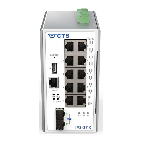
Page 7: Panel Layout
Cable Specifications The following table contains various cable specifications for the Managed Switch. Please make sure to use the proper cable when connecting the Managed Industrial PoE Gigabit Ethernet Switches. Cable Type Description UTP Category 3, 4, 5 (100 meters max.) 10BASE-T EIA/TIA- 568 150-ohm STP (100 meters max.) UTP Cat. - Page 8 Insert a pin or paper clip to press the Reset Button for 10 seconds to reset the device back to defaults. B. USB host (for more information, please refer to chapter 4.3) C. Console port (RJ-45 to RS-232) D. LEDs (for more information, please refer to chapter 3.1) E.
-
Page 9: Installation
2. INSTALLATION To properly install the Managed Industrial PoE Gigabit Ethernet Switch, please follow the procedures listed below. Procedures covered in this chapter are described below in separate sections. Installation Requirements Unpacking the Managed Industrial PoE Gigabit Ethernet Switch ... -
Page 10: Installing The Managed Industrial Poe Gigabit Ethernet Switch
Note: If any of the above items is found missing or damaged, please contact your local sales representative for support or replacement. 2.3 Installing the Managed Industrial PoE Gigabit Ethernet Switch ATTENTION This product is intended to be mounted to a well-grounded mounting surface, such as a metal panel. - Page 11 Figure 6. Install the Managed Industrial PoE Gigabit Ethernet Switch in vertical direction. Figure 7. Install the Managed Industrial PoE Gigabit Ethernet Switch in horizontal direction Grounding the Managed Industrial PoE Gigabit Ethernet Switch Grounding helps to limit the effects of noise due to electromagnetic interference (EMI). Be sure to install the ground connection from the ground screw to the grounding surface before connecting devices.
-
Page 12: Powering The Managed Industrial Poe Gigabit Ethernet Switch
Figure 8. Grounding wiring 2.4 Powering the Managed Industrial PoE Gigabit Ethernet Switch The Managed Industrial PoE Gigabit Ethernet Switch can be used with DC power 48-54 VDC with the terminal block. The terminal block is located on the upper panel of the Managed Industrial PoE Gigabit Ethernet Switch. - Page 13 Tighten the wire-clamping screws to fix DC wires by using a flat-head screwdriver. Wire-clamping screws Relay Alarm Output Configuration Relay alarm has 3 contacts on the terminal block used to connect alarm devices such as speakers or LEDs to alert users when the redundant power or a port link is disconnected. The right contact is normal closed, the left contact is normal open, and the middle contact is com shared by normal open and normal closed.
-
Page 14: Connecting The Switch To Network
Note: If there is no power redundancy, the relay alarm is not available. Insert positive or negative wire Use a flat-head screwdriver to loosen and tighten the screw Figure 9. Illustration of wiring the terminal blocks 2.5 Connecting the switch to Network Connect to Network This Managed Industrial PoE Gigabit Ethernet Switch has 2 uplink ports (RJ-45 or SFP) and 8 downlink 10/100/1000Mbps RJ-45 ports for you to implement it in your... -
Page 15: Led Definitions
3.1 LED Definitions Definition Color Operation Device is powered down. Power Green Device is powered on. Device is powered down. Power Green Device is powered on. Orange System is booting up. Green System is working normally. When a USB is inserted, the Status LED indicator will blink 3 times in green. -
Page 16: Fault Identification
4.1 Fault Identification Identifying faults can greatly reduce the time required to find the problem and solution. Users may perform local or remote checks to find the problems. Local Check Users can perform local checks by observing LED indicators status. ... -
Page 17: Firmware And Configuration Upgrade
(Logic unit number, LUN) File system : FAT12, FAT16, FAT32, NTFS3.1(read-only) and before Automatic Firmware and Configuration Upgrade Process Preparation steps before inserting the USB disk Rename the firmware name as: cts-fw-<model_name>.<admin_user>.<password> Rename the configuration file name as: cts-cfg-<model_name>.<admin_user>.<password>... - Page 18 Firmware Upgrade Firmware upgrade Plug in USB disk and reboot* Upgrade Complete Configuration Upgrade Configuration upgrade and reboot** *Firmware upgrade process would be skipped if: The firmware file is not authorized (wrong admin/password or unauthorized). The file is too big (>16MB). ...
Need help?
Do you have a question about the IPS-3110 and is the answer not in the manual?
Questions and answers