
Related Manuals for CTS IPS-3120-PoE++


Summary of Contents for CTS IPS-3120-PoE++
- Page 1 IPS-3120-PoE++ Expansion Module Managed Industrial PoE Gigabit Ethernet Switch Quick Installation Guide Version 0.91...
- Page 2 Trademarks Contents are subject to revision without prior notice. All other trademarks remain the property of their respective owners. Copyright Statement Copyright © 2017 All Rights Reserved. This publication may not be reproduced as a whole or in part, in any way whatsoever unless prior consent has been obtained.
- Page 3 Revision History Version Date Description 0.90 20170727 First release 0.91 20171208 Modify the dimension...
-
Page 4: Table Of Contents
Table of Contents OVERVIEW ..................5 1.1 Package Contents ..................5 1.2 Dimension ....................5 1.3 Panel ......................6 2. LED Indicators ....................8 3. Installation ....................9 3.1 DIN-Rail Mounting ..................9 3.2 Assemble and Disassemble IPS-3120-PoE++ Expansion Module ..10 3.3 Powering the Managed Industrial PoE Gigabit Ethernet Switch ..... -
Page 5: Overview
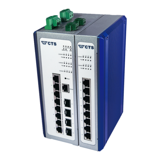
1. OVERVIEW This IPS-3120-PoE++ Expansion Module is an IP30 rated switch with integrated DIN-Rail mount. The industrial gigabit managed Ethernet switch has 8 IEEE 802.3at compliant ports (30W/port) and 4 dual-rate (100/1000) SFP slots, suitable for applications that require high bandwidth and long distance communication. -
Page 6: Panel
1.3 Panel Front Panel A. Reset Button: Insert a pin or paper clip to press the Reset Button for 5 seconds to restart the system. Insert a pin or paper clip to press the Reset Button for 10 seconds to reset the device back to defaults. - Page 7 Rear Panel Side Panel F. Din-Rail metal spring Top Panel G. Ground screw H. Power input 1, Power input 2: The input voltage range is 48~54VDC, suggest to use 12 AWG wire gauge. I. Relay Alarm: The default setting is normal open, the capacity of relay alarm is 1A/30VDC.
-
Page 8: Led Indicators
2. LED Indicators Definition Color Operation Device is powered down. Power Green Device is powered on. Device is powered down. Power Green Device is powered on. Orange System is booting up. Green System is working normally. Green When upgrade procedure is completed, the Status Blinking LED indicator will blink 3 times in green. -
Page 9: Installation
3. Installation To properly install the PoE Gigabit Ethernet Switch, please follow the procedures listed below. Procedures covered in this chapter are described below in separate sections. ATTENTION Be sure to power off before installing or wiring your Managed Industrial PoE Gigabit Ethernet Switch. Be sure to calculate the maximum possible current in each power wire and common wire. -
Page 10: Assemble And Disassemble Ips-3120-Poe++ Expansion Module
3.2 Assemble and Disassemble IPS-3120-PoE++ Expansion Module Combine two models into one model. If you want to use both your IPS-3108-EXP and IPS-3112-PoE++ as an IPS-3120-PoE++. Dock IPS-3108-EXP into the IPS-3112-PoE++ as shown in the illustration below. Assemble: 1 PCIE connector and 3 support pins on the IPS-3108-EXP aligned with the corresponding holes on the IPS-3112-PoE++, and then close together, when hears the click sound, that has been completed close, 2 devices will combine into IPS-3120-PoE++ Expansion Module. - Page 11 Disassemble: There is a slide switch on the rear side of the IPS-3112-PoE++, push the slide switch down to the bottom, both hands hold IPS-3112-PoE++ and IPS-3108-EXP respectively, and separate it, then it restored to 2 devices.
-
Page 12: Powering The Managed Industrial Poe Gigabit Ethernet Switch
Powering the Managed Industrial PoE Gigabit Ethernet Switch The Managed Industrial PoE Gigabit Ethernet Switch can be used with DC power 48-54 VDC with the terminal block. The terminal block is located on the upper panel of the Managed Industrial PoE Gigabit Ethernet Switch. Before powering the Managed Industrial PoE Gigabit Ethernet Switch, please make sure that network cables and power cables are securely connected. - Page 13 Tighten the wire-clamping screws to fix DC wires by using a flat-head screwdriver. Wire-clamping screws Relay Alarm Output Configuration Relay alarm has 2 contacts on the terminal block used to connect alarm devices such as speakers or LEDs to alert users when the redundant power or a port link is disconnected.
-
Page 14: Web Console Configuration
Tighten the wire-clamping screws to fix the wires by using a flat-head screwdriver as above. Note: If there is no power redundancy, the relay alarm is not available. 4. Web Console Configuration Web Console Configuration Information Default IP address: 192.168.0.1 Default Login Account: admin Default login Password: Notes: By default, the password is not enabled. -
Page 15: Hardware Replacement Procedures
Also be sure that the length of any twisted-pair connection does not exceed 100 meters (328 feet). Diagnosing LED Indicators: To assist in identifying problems, the switch can be easily monitored with the LED indicators which help to identity if any problems exist. ...
Need help?
Do you have a question about the IPS-3120-PoE++ and is the answer not in the manual?
Questions and answers