Table of Contents
Advertisement
Quick Links
IES-3006 SERIES
Industrial Ethernet Switch
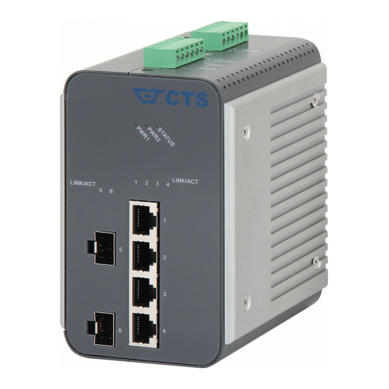
IES-3006SFP-DR
4 Ports 10/100/1000Base-T plus 2 Ports 100/1000Base-X
Industrial Ethernet Switch
IES-3006SFP-F1-DR
5 Ports 10/100/1000Base-T plus 1 Port 100/1000Base-X
Industrial Ethernet Switch
IES-3006TP
6 Ports 10/100/1000Base-T Industrial Ethernet Switch
User's Guide
Version 0.91
Advertisement
Table of Contents

Subscribe to Our Youtube Channel
Related Manuals for CTS IES-3006 Series


Summary of Contents for CTS IES-3006 Series
- Page 1 IES-3006 SERIES Industrial Ethernet Switch IES-3006SFP-DR 4 Ports 10/100/1000Base-T plus 2 Ports 100/1000Base-X Industrial Ethernet Switch IES-3006SFP-F1-DR 5 Ports 10/100/1000Base-T plus 1 Port 100/1000Base-X Industrial Ethernet Switch IES-3006TP 6 Ports 10/100/1000Base-T Industrial Ethernet Switch User’s Guide Version 0.91...
- Page 2 Revision History Version Date Description 0.90 20141119 First release 0.91 20151104 Revise series wiring connection illustration Section 2.5...
- Page 3 Trademarks CTS is a registered trademark of Connection Technology Systems Inc. Contents are subject to revision without prior notice. All other trademarks remain the property of their respective owners. Copyright Statement Copyright 2014 Connection Technology Systems Inc. This publication may not be reproduced as a whole or in part, in any way whatsoever unless prior consent has been obtained from Connection Technology Systems Inc.
-
Page 4: Table Of Contents
Table of Contents 1. OVERVIEW ....................5 1.1 Specification ....................5 1.2 Panel Layout ....................6 2. INSTALLATION ..................10 2.1 Installation Requirements ................10 2.2 Checking the Package Contents..............10 2.3 Installing the Industrial Ethernet Switch ............11 2.4 Wiring the Redundant Power Inputs ............12 2.5 Wiring the Alarm Contact ................ -
Page 5: Overview
They are fully compliant with IEEE802.3, 802.3u, 802.3x, 802.3ab, 802.3z and 802.3x standards. Besides, redundant power supplies are both offered on IES-3006 series Industrial Ethernet Switches for users to create a reliable and stable network in the event of power failure. By employing Store-and-Forward switching mechanism, the switch provides low latency and faster data transmission. -
Page 6: Panel Layout
Cable Type Description UTP Category 3, 4, 5 (100 meters max.) 10BASE-T EIA/TIA- 568 150-ohm STP (100 meters max.) UTP Cat. 5 (100 meters max.) 100BASE-TX EIA/TIA-568 150-ohm STP (100 meters max.) UTP Cat. 5e (100 meters max.) 1000BASE-T UTP Cat. 5 (100 meters max.) EIA/TIA-568B 150-ohm STP (100 meters max.) 100BASE-FX Multi-mode fiber module(2km) / Single-mode fiber module... - Page 7 ➌ ➊ ➋ Figure 2. Front Panel for 5 Ports 10/100/1000Base-T + 1 port 100/1000Base-X ➌ ➋ ➊ Figure 3. Front Panel for 6 Ports 10/100/1000Base-T ➊ 10/100/1000Mbps RJ-45 LAN ports ➋ 10/100/1000Mbps RJ-45 port(s) or 100/1000Mbps SFP port(s) ➌ LEDs (for more information, please see chapter 3.1)
- Page 8 Rear Panel Figure 4. Rear Panel DIN-Rail metal spring (for more information, please see chapter 2.3) Top Panel ➑ ➎ ➐ ➏ Figure 5. Top Panel ➎ Reset Button: Insert a pin or paper clip to press the Reset Button for 5 seconds to restart the system ...
- Page 9 ➐ Ground wire screw (for more information, please see chapter 2.3) ➑ DIP Switch (for more information, please see chapter 3.2)
-
Page 10: Installation
2. INSTALLATION To properly install the Industrial Ethernet Switch, please follow the procedures listed below. Procedures covered in this chapter are described below in separate sections. Installation Requirements Unpacking the Industrial Ethernet Switch Installing the Industrial Ethernet Switch ... -
Page 11: Installing The Industrial Ethernet Switch
If any of the above items is found missing or damaged, please contact your local sales representative for support or replacement. 2.3 Installing the Industrial Ethernet Switch ATTENTION This product is intended to be mounted to a well-grounded mounting surface, such as a metal panel. DIN-Rail Mounting STEP 1 Insert the top of the DIN-Rail... -
Page 12: Wiring The Redundant Power Inputs
Grounding the Industrial Ethernet Switch Grounding helps to limit the effects of noise due to electromagnetic interference (EMI). Be sure to install the ground connection from the ground screw to the grounding surface before connecting devices. Figure 6. Grounding wire 2.4 Wiring the Redundant Power Inputs The Industrial Ethernet Switch can be used with DC power 48-54 VDC with 2 terminal blocks. -
Page 13: Wiring The Alarm Contact
STEP 1 : Insert the negative/positive DC wires into the V-/V+ terminals. STEP 2 : Use a small flat-blade screwdriver to tighten the wire-clamp screws on the front of the terminal block connector. STEP 3 : Insert the plastic terminal block connector prongs into the terminal block receptor, which is located on the IES’s top panel. -
Page 14: Connecting The Switch To Network
The two wires attached to the Fault contacts form an open circuit when : The IES has lost power from one of the DC power inputs. One of the ports for which the corresponding Port Alarm DIP Switch is set to ON be not properly connected. (parallel connection) 2.6 Connecting the switch to Network Connect to Network... -
Page 15: Operation
3. OPERATION The Industrial Ethernet Switch is Plug & Play compliant. Real-time operational status can be monitored through a set of LED indicators located on the front panel. 3.1 LED Definitions Definition Color Operation Device is powered down. PWR1 Power Green Device is powered up. -
Page 16: Maintenance
4. MAINTENANCE It is easy to use and maintain this Industrial Ethernet Switch. The procedures are suggested when you want to identify faults or perform hardware replacement. 4.1 Fault Identification Identifying faults can greatly reduce the time required to find the problem and solution. Users may perform local or remote checks to find the problems.
Need help?
Do you have a question about the IES-3006 Series and is the answer not in the manual?
Questions and answers