Table of Contents
Advertisement
Quick Links
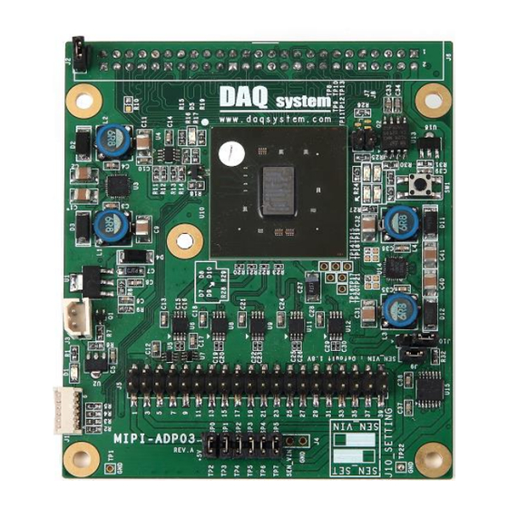
MIPI-ADP03
User Manual
Version 1.1
ⓒ 2005 DAQ SYSTEM Co., Ltd. All rights reserved.
Microsoft® is a registered trademark; Windows®, Windows NT®, Windows XP®, Windows 7®, Windows 8®, Windows 10®
All other trademarks or intellectual property mentioned herein belongs to their respective owners.
Information furnished by DAQ SYSTEM is believed to be accurate and reliable, However, no responsibility is assumed by DAQ SYSTEM for its use, nor
for any infringements of patents or other rights of third parties which may result from its use. No license is granted by implication or otherwise under
any patent or copyrights of DAQ SYSTEM.
The information in this document is subject to change without notice and no part of this document may be copied or reproduced without the prior
written consent.
Advertisement
Table of Contents

Subscribe to Our Youtube Channel
Related Manuals for DAQ system MIPI-ADP03


Summary of Contents for DAQ system MIPI-ADP03
- Page 1 All other trademarks or intellectual property mentioned herein belongs to their respective owners. Information furnished by DAQ SYSTEM is believed to be accurate and reliable, However, no responsibility is assumed by DAQ SYSTEM for its use, nor for any infringements of patents or other rights of third parties which may result from its use. No license is granted by implication or otherwise under any patent or copyrights of DAQ SYSTEM.
-
Page 2: Table Of Contents
MIPI-ADP03 User’s Manual Contents 1. MIPI-ADP03 Introduction -------------------------------------------------------- 2. MIPI-ADP03 Function -------------------------------------------------------------- J2 Connector ------------------------------------------------------------------------------ 2-2 J4 Connector --------------------------------------------------------------------------------- 2-3 J5 Connector ------------------------------------------------------------------------ 2-4 J6 Connector --------------------------------------------------------------------------------- 2-5 J9/J10 Connector ---------------------------------------------------------------------------- 2-6 SW1 ------------------------------------------------------------------------ Appendix A-1 Board Size ----------------------------------------------------------------------------------- 15... -
Page 3: Mipi-Adp03 Introduction
MIPI-ADP03 User’s Manual 1. MIPI-ADP03 Introduction MIPI-ADP03 board is a function of transferring to the USB-DIO01 board after being converted into parallel signals received from the MIPI serial signal through MIPI SENSOR. The maximum transmission speed is about 1.2Gbps/Lane. MIPI-SENSOR01... - Page 4 MIPI-ADP03 User’s Manual The block diagram of MIPI-ADP03 is in Figure 1-2. All functions are controlled by the FPGA, and also, the power received from USB3-DIO01 supply to MIPI sensor board. USB3-DIO01 MIPI SENSOR MIPI-ADP01 MIPI Sensor Upto 800MHZ 4Lane Data...
- Page 5 MIPI-ADP03 User’s Manual Some of the features of the I2C-related and USB3-DIO01 sensor INI files, they are as follows: This will be described with reference to the USB3-DIO01 sample program. (We have been promoting integration of Input/Output function, so the sample program may be changed.)
- Page 6 MIPI-ADP03 User’s Manual Example 1) OV5640(5M).ini File Structure [REGISTER] Slave 0x3C //change slave ID as Sensor SLEEP 0x3103 0x11 0x3008 0x82 0x3008 0x42 0x3103 0x03 0x3017 0x00 0x3018 0x00 0x3034 0x1a 0x3035 0x12 0x3036 0x69 0x3037 0x13 0x3108 0x01 0x3630 0x36...
- Page 7 MIPI-ADP03 User’s Manual When you want to control the FPGA of MIPI-ADP03, Slave Address will be fixed to 0x14. The MIPI control signals that you want have to be written the data to the corresponding address register. Example 2) When the FPGA controls, SLAVE ADDRESS(7bit) is fixed to 0x14.
- Page 8 MIPI-ADP03 User’s Manual Address Command Data(7-0) Data(1-0) I2C Read / Write block is composed of a function associated with the transmission of the I2C (1) “Init” Button It will initiate the resources for the I2C system. (2) “Write” Button Transmit the data through I2C for control to MIPI or CMOS camera.
- Page 9 MIPI-ADP03 User’s Manual “Len.” : Address Value(Length) “Data Len :” : Data Value(Length) “Data :” : Data that will transmit (6) “Reset” Button Re-initialize the resources of the I2C system. (6) “Virtual Channel” Button : How to use the I2C Reae/Write box is as follows.
-
Page 10: Mipi-Adp03 Function
MIPI-ADP03 User’s Manual 2. MIPI-ADP03 Function MIPI-ADP03 names and functions of each are described below. MIPI-ADP03 Board SEN_VIN Name Description U1, U3, U14 1.0V, 1.8V, 3.3V Low Voltage Level Translator U6, U8, U9, U11, U12 Differential Translator/Repeater FPGA U15, U18... -
Page 11: J2 Connector
MIPI-ADP03 User’s Manual LED is also to check for internal operations. LED D1 turns on when power 3.3V is applied to the board. LED D5 turns on when power is applied to the board and the initialization ends up. LED D7 turns on when MIPI signal detects. -
Page 12: J5 Connector
MIPI-ADP03 User’s Manual 2-3 J5 Connector It is connected to the MIPI SENSOR board, signals are as follows. 25 27 [Figure 2-2. J5 Connector (Top View)] [Table 1. J5 Connector Description] Name Description Remark User Defined Power Connected SP0 of J4... -
Page 13: J6 Connector
MIPI-ADP03 User’s Manual DATAN_3 MIPI 4 Lane Negative Ground Ground Ground CLKP MIPI Clock Positive Ground CLKN MIPI Clock Negative MCLK Master Clock Ground Ground Ground User Defined Power Connected SP4 of J4 User Defined Power Connected SP5 of J4 2-4 J6 Connector The following figure shows the external input and output board of J6 connector pin map. - Page 14 MIPI-ADP03 User’s Manual DIO_10 Digital Input/Output 10 DIO_11 Digital Input/Output 11 DIO_12 Digital Input/Output 12 DIO_13 Digital Input/Output 13 DIO_14 Digital Input/Output 14 DIO_15 Digital Input/Output 15 Ground Ground DIO_16 Digital Input/Output 16 DIO_17 Digital Input/Output 17 DIO_18 Digital Input/Output 18...
-
Page 15: J9/J10 Connector
MIPI-ADP03 User’s Manual 2-5 J9/J10 Connector When you connect J9, 1.8V is connected to SEN_VIN. At this time, if the pin 2-3 connect at J10, SENSOR control signals became the level 1.8V (mclk, control, enc, reset). VIO of J10 is an option for power settings from internal. When 1..2 connection, I2C can control with the DIO board. -
Page 16: Appendix
MIPI-ADP03 User’s Manual Appendix A-1 Board Size The external sizes of the board are as follows. 76.2 12.4 88.9 < Top View >... -
Page 17: Repair Regulations
MIPI-ADP03 User’s Manual A-2 Repair Regulations Thank you for purchasing a DAQSYSTEM product. Please refer to the following regarding Customer Service regulated by DAQSYSTEM. (1) Read the user manual and follow the instructions before using the DAQSYSTEM product. (2) When returning the product to be repaired, please write down the symptoms of the failure and send it to the head office. - Page 18 MIPI-ADP03 User’s Manual MEMO Contact Point Web sit : https://www.daqsystem.com Email : postmaster@daqsystem.com...
Need help?
Do you have a question about the MIPI-ADP03 and is the answer not in the manual?
Questions and answers