Table of Contents
Advertisement
Quick Links
Blind control system
Blind controller insert DC 24 V
Blind controller insert DC 24 V
Order-No. : 0388 00
Operating instructions
1 Safety instructions
Electrical equipment may only be installed and fitted by electrically skilled persons.
Failure to observe the instructions may cause damage to the device and result in fire and
other hazards.
To supply the insert and to control the extension inputs it is necessary to use a power
supply unit that provides DC 24 V SELV. This ensures reliable isolation between the
primary and secondary sides.
Risk of injury. Use the device only for controlling Venetian blind and roller shutter
motors or awnings. Do not use it to switch other loads.
Use only Venetian blind drives with mechanical or electronic limit switches. Check the
limit switches for correct adjustment. Observe the specifications of the motor
manufacturers. Device can be damaged.
These instructions are an integral part of the product, and must remain with the end
customer.
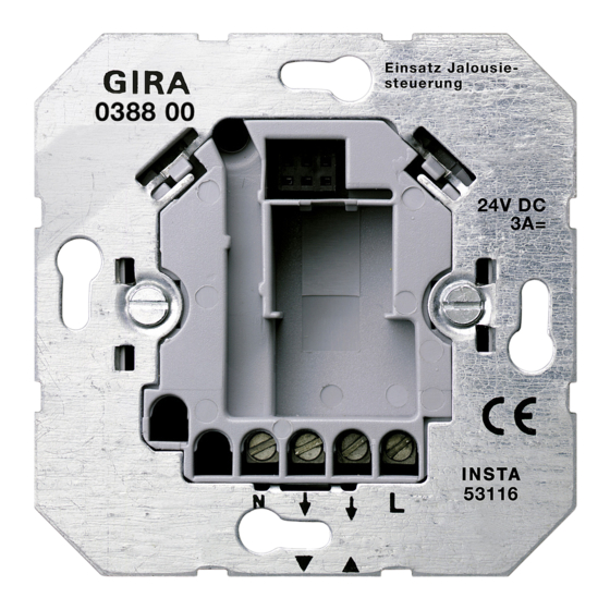
2 Device components
(1) 24 V insert
(2) Frame
(3) Shutter cover
(4) Terminals
(5) Space for sensor terminal block
3 Function
Intended use
-
Control of electrically-driven Venetian blinds, shutters and awnings that are operated with
DC 24 V SELV
-
Operation with suitable shutter cover
-
Installation in appliance box to DIN 49073
32545312
10499098 I00
Figure 1
17.05.2011
1/8
Advertisement
Table of Contents

Subscribe to Our Youtube Channel
Related Manuals for Gira 0388 00


Summary of Contents for Gira 0388 00
- Page 1 Blind control system Blind controller insert DC 24 V Blind controller insert DC 24 V Order-No. : 0388 00 Operating instructions 1 Safety instructions Electrical equipment may only be installed and fitted by electrically skilled persons. Failure to observe the instructions may cause damage to the device and result in fire and other hazards.
- Page 2 Blind control system Blind controller insert DC 24 V Product characteristics Integration into groups or master control via extension units with additional 24 V inserts Operation as a main device or extension unit Supports sensor functions of the cover Several motors can be connected in parallel The direction of rotation of the shutter motor is determined by switching the polarity of the motor outputs "pole-changing principle"...
- Page 3 Blind control system Blind controller insert DC 24 V Figure 3: Connection diagram for insert Connect the shutter motor and power supply unit (8) to the insert (1) according to the connection diagram (Figure 3). For a shutter cover with sensor evaluation, install the sensor cable in accordance with (Figure 8) or (Figure 9) (Installing the sensor cable).
- Page 4 Blind control system Blind controller insert DC 24 V Figure 4: Connection assignment of extension inputs for the corresponding directions of motion The direction of rotation of the shutter motor is determined by the polarity of the two extension inputs. Connection illustration (Figure 4) shows the direction of motion of the blind/shutter for the depicted connection assignments.
- Page 5 Blind control system Blind controller insert DC 24 V Figure 6: Connection diagram for insert with mechanical extension The insert can only be operated with a mechanical extension if the insert and the extension are supplied by the same power supply unit. The insert and extension then have the same "-" potential, and it is sufficient to connect the "+"...
- Page 6 Blind control system Blind controller insert DC 24 V i The sensor cable must not be too long, because otherwise interference from other loads and cables may occur. This may result in malfunctions. Therefore use only shielded cables, and connect the shielding to earth. The total length must not exceed 20 m; avoid proximity to other electrical facilities.
- Page 7 Blind control system Blind controller insert DC 24 V Route the sensor cable behind the supporting plate (14) and through the cable duct to the connecting terminal (13) (Figure 9). Connect the cable (see "Connecting sensors to terminal block") Connecting sensors to terminal block Figure 10: Connection to the terminal block Connect sensors as shown in connection illustration (Figure 10).
- Page 8 The warranty is provided in accordance with statutory requirements via the specialist trade. Please submit or send faulty devices postage paid together with an error description to your responsible salesperson (specialist trade/installation company/electrical specialist trade). They will forward the devices to the Gira Service Center. Gira Giersiepen GmbH & Co. KG...
Need help?
Do you have a question about the 0388 00 and is the answer not in the manual?
Questions and answers