
Related Manuals for Threshold STUDIO MCGEE Marvale TGAVC68-21


Summary of Contents for Threshold STUDIO MCGEE Marvale TGAVC68-21
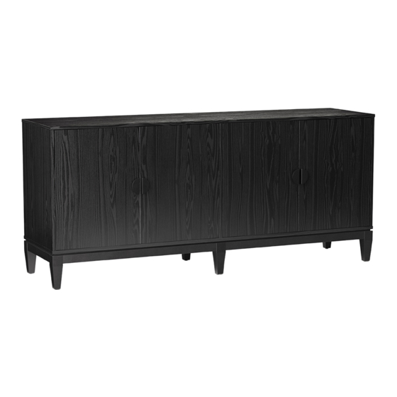
- Page 1 Marvale 4 Door Media Stand Style # TGAVC68-21 DPC-item #: 249-10-9873 >> Assembly instructions © 2023 Target. The Bullseye Design is a trademark of Target Brands, Inc. All rights reserved.
-
Page 2: Before You Begin
Congratulations on your latest Target purchase. Now what? Don’t start sweating over this box of parts. This will be easy. We did the hard work for you. All you need to do is follow our simple instructions and you’ll be on your way to transforming your room in no time. Good luck –... - Page 3 hardware (H1) x 10 (H2) x 10 (H3) x 12 (H4) x 16 (H5) x 16 cam lock cam bolt M8 x 30 mm 1/4” x 15 mm bolt lock washer wood dowel (H6) x 16 (H7) x 24 (H8) x 6 (H9) x 8 (H10) x 2 flat washer...
- Page 4 hardware (H16) x 10 (H17) x 2 (H18) x 1 (H19) x 2 cam lock cover M4 x 50 mm screw hex wrench tipping restraint hardware kit (inside plastic bag) Spare hardware...
- Page 5 exploded diagram ITEM DESCRIPTION Top panel Bottom panel Back panel Side panel Partition panel Top reinforcement Adjustable Shelf Side / Middle right door Middle left door Leg assembly Bottom stretcher...
-
Page 6: How To Use The Cam Lock System
how to use the cam lock system Push cam into panel - arrow Align cam bolt(s) with cam(s) Screw cam bolt into panel feature on cam top points to and insert all the way into panel edge cross-bored hole(s) 190°-230° Panels should be tight against Rotate cam(s) clockwise each other and connection... - Page 7 step 1: attach bottom stretchers to one leg assembly NOTE: DO NOT fully tighten all bolts until you finish assembling all parts. Once assembled, go back and fully tighten all bolts. This will make the The metal tabs face inward and assembly easier.
-
Page 8: Step 2: Install The Base
step 2: install the base (H4) x 2 (H5) x 2 1/4” x 15 mm bolt lock washer (H18) x 1 (H6) x 2 hex wrench flat washer 2.1. Repeat the same process to attach the other leg assembly (J) to the bottom stretchers (K). - Page 9 step 3: attach the door stoppers to the top panel NOTE: DO NOT use power tools. (H10) x 2 (H11) x 4 door stopper M3 x 10 mm screw Pilot hole 3.1. Using the pilot holes as a guide, attach the door stoppers (H10) to the top panel (A) with four 10 mm screws (H11).
- Page 10 step 4: fasten the top reinforcement NOTE: DO NOT use power tools. (H8) x 6 M4 x 38 mm screw The countersunk holes face upward 4.1. Using the pilot holes as a guide, orient and fasten the top reinforcement (F) to the top panel (A) with six 38 mm screws (H8).
- Page 11 step 5: prepare top and bottom panels assembly (H2) x 10 cam bolt 5.1. Securely screw the cam bolts (H2) into the designated small holes on the top and bottom panels (A and B).
- Page 12 step 6: attach the side panels and partition panel to the top panel The pilot holes for door hinges face inward and are located at front of the unit. (H1) x 6 (H3) x 6 cam lock M8 x 30 mm wood dowel 6.1.
- Page 13 step 7: attach the bottom panel to the vertical panels (H1) x 4 (H3) x 6 cam lock M8 x 30 mm wood dowel (H17) x 2 M4 x 50 mm screw 7.1. Insert six wood dowels (H3) into the bottom inner holes of both side panels (D) and the partition panel (E). 7.2.
- Page 14 step 8: fasten the back panel The adhesive tape faces outward. CAUTION: Heavy! You may need assistance with this step. (H7) x 24 M3.5 x 15 mm washer head screw 8.1. Now, go back and tighten all Cam Locks and Screws. Make sure that all the parts are tight and there are no gaps between the pieces. This will help keep the unit square.
-
Page 15: Step 9: Attach The Base
step 9: attach the base (H4) x 12 (H5) x 12 1/4” x 15 mm bolt lock washer (H6) x 12 (H18) x 1 flat washer hex wrench 9.1. Insert twelve 15 mm bolts (H4) with the lock washers (H5) and flat washers (H6) through the metal tabs on the assembled base and securely screw into the bottom panel (B). - Page 16 step 10: install the door handles and hinges NOTE: DO NOT use power tools. (H12) x 8 (H13) x 16 door hinge M4 x 15 mm screw (Nickel) (H14) x 4 (H15) x 8 handle M4 x 18 mm handle bolt 10.1.
-
Page 17: Step 11: Attach The Doors
step 11: attach the doors CAUTION: Heavy! You may need assistance with this step. (H13) x 32 M4 x 15 mm screw (Nickel) 11.1. Ask for assistance to lift the assembled unit upright and position it near the final location. 11.2. - Page 18 step 12: install the adjustable shelves and put cam lock covers (H9) x 8 (H16) x 10 shelf support cam lock cover 12.1. Open the doors and insert four shelf supports (H9) in the holes at the desired height inside each compartment. Make sure you place the four shelf supports at the same level to level the shelf.
- Page 19 step 13: adjust the doors Depth adjustment Horizontal adjustment Vertical adjustment Floor leveler Raise or lower the floor levelers by hand to correct tilting and / or level doors. 13.1. NOTE: Do not open the two middle doors at the same time.
- Page 20 step 14: install the tipping restraint hardware kit Wooden stud Wall Short screw Wall (H19) x 2 tipping restraint hardware kit Metal bracket Nylon strap Long screw Tools required: Phillips screwdriver, stud finder, tape measure, pencil, power drill and 1/8” drill bit (not provided). 14.1.
- Page 21 FURNITURE TIPPING RESTRAINT YOUNG CHILDREN MAY BE INJURED BY TIPPING FURNITURE AND YOU MUST USE THIS TIPPING RESTRAINT TO ATTACH THIS UNIT TO THE WALL, TO PREVENT ACCIDENTS AND/OR INJURIES. TO PROVIDE PROTECTION AGAINST THE UNEXPECTED TIPPING OF FURNITURE DUE TO IMPROPER USE. USE OF TIP-OVER RESTRAINTS MAY ONLY REDUCE, BUT NOT ELIMINATE, THE RISK OF TIP-OVER.
-
Page 22: Care And Maintenance
Care and Maintenance Use a soft, clean cloth that will not scratch the surface when dusting. Use of furniture polish is not necessary. Should you choose to use polish, test first in an inconspicuous area. Using solvents of any kind on your furniture may damage the finish. ... - Page 23 M A X I M U M R E C O M M E N D E D W E I G H T L O A D S MANUFACTURER: Whalen Furniture Manufacturing CATALOG: Marvale 4 Door Media Stand MODEL # TGAVC68-21 FITS UP TO MOST 162.6 cm / 64 in.
- Page 24 The maximum recommended weight allowance is 40.8 kg / 90 lb for top panel. The maximum recommended weight allowance is 22.7 kg / 50 lb for shelves. This unit is not intended for use with CRT TVs. The top surface maximum weight capacity is 90 lb (40.8 kg) and maximum load 64 in.
Need help?
Do you have a question about the STUDIO MCGEE Marvale TGAVC68-21 and is the answer not in the manual?
Questions and answers