
Related Manuals for Threshold STUDIO MCGEE Kennington TGT32CB-3


Summary of Contents for Threshold STUDIO MCGEE Kennington TGT32CB-3
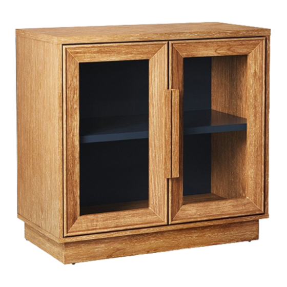
- Page 1 Kennington 2 Door 32" Cabinet Style # TGT32CB-3 DPC-item #: 249-17-1551 >> Assembly instructions © 2023 Target. The Bullseye Design is a trademark of Target Brands, Inc. All rights reserved.
-
Page 2: Before You Begin
Congratulations on your latest Target purchase. Now what? Don’t start sweating over this box of parts. This will be easy. We did the hard work for you. All you need to do is follow our simple instructions and you’ll be on your way to transforming your room in no time. Good luck –... - Page 3 hardware (H2) x 16 (H3) x 12 (H4) x 20 (H5) x 12 (H1) x 16 cam bolt M8 x 30 mm M3.5 x 15 mm M3.5 x 12 mm cam lock wood dowel washer head screw pan head screw (H6) x 2 (H9) x 4 (H10) x 16...
- Page 4 exploded diagram DESCRIPTION Top panel Adjustable shelf Base Left side panel Right side panel Top stretcher Left door Right door Handle Back panel...
-
Page 5: How To Use The Cam Lock System
how to use the cam lock system Push cam into panel - arrow Align cam bolt(s) with cam(s) Screw cam bolt into panel feature on cam top points to and insert all the way into panel edge cross-bored hole(s) 190° -230° Panels should be tight against Rotate cam(s) clockwise each other and connection... - Page 6 step 1: install the roller catch plates NOTE: DO NOT use power tools. The projection points towards the back of the unit (H7) x 2 (H5) x 4 roller catch metal plate M3.5 x 12 mm pan head screw 1.1. Using the pilot holes as a guide, orient and attach the roller catch metal plates (H7) to the bottom base (C) with four 12 mm pan head screws (H5).
- Page 7 step 2: prepare the top panel and base assembly (H2) x 12 cam bolt 2.1. Securely screw the cam bolts (H2) into the designated small holes on the top panel (A) and the base (C).
- Page 8 step 3: prepare the side panels assembly (H2) x 4 cam bolt 3.1. Securely screw the cam bolts (H2) into the designated small holes on the side panels (D and E).
- Page 9 step 4: attach the top stretchers between the side panels (H1) x 4 cam lock The cam lock housing point towards the back of the unit and are located at the bottom 4.1. Orient and attach the top stretchers (F) between the side panels (D and E) using four cam locks (H1).
- Page 10 step 5: attach both side panels to the base (H1) x 4 (H3) x 4 cam lock M8 x 30 mm wood dowel Floor leveler The back edges are flush with each other. 5.1. Insert four 30 mm wood dowels (H3) into the bottom inner holes of the side panels (D and E). 5.2.
- Page 11 step 6: attach the top panel to the previous assembly The pilot holes face backward (H1) x 8 (H3) x 8 cam lock M8 x 30 mm wood dowel 6.1. Insert eight 30 mm wood dowels (H3) into the top inner holes of both top stretchers (F) and side panels (D and E). 6.2.
- Page 12 step 7: attach the back panel to the cabinet frame NOTE: DO NOT use power tools. (H4) x 20 M3.5 x 15 mm washer head screw Adhesive tape faces outward 7.1. Now, go back and tighten all cam locks and screws. Make sure that all the parts are tight and there are no gaps between the parts. This will help keep the unit square.
- Page 13 step 8: install the roller catches The roller runs against the bottom edge NOTE: DO NOT use power tools. (H5) x 4 (H6) x 2 M3.5 x 12 mm roller catch pan head screw 8.1. Using the pilot holes as a guide, orient and attach one roller catch (H6) to each door frame (G and H) with two 12 mm pan head screws (H5).
- Page 14 step 9: attach the door hinges NOTE: DO NOT use power tools. (H9) x 4 (H10) x 8 door hinge M3.5 x 15 mm zinc screw 9.1. Extend two hinges (H9) and rest the hinge cups onto the cutouts of each door (G and H). 9.2.
-
Page 15: Step 10: Install The Handles
step 10: install the handles NOTE: DO NOT use power tools. (H11) x 4 3/16” x 35 mm handle bolt 10.1.Attach one handle (I) to the front of each door (G and H) with two 35 mm handle bolts (H11). - Page 16 step 11: install the doors CAUTION: Heavy! You may need assistance with this step. (H10) x 8 M3.5 x 15 mm zinc screw 11.1. Ask for assistance to lift the assembled unit upright and position it near the desired location. 11.2.
- Page 17 step 12: install the adjustable shelf (H5) x 4 (H8) x 4 M3.5 x 12 mm shelf support pan head screw 12.1. Open the doors and insert four shelf supports (H8) into the desired holes in the side panels (D and E). Be sure to place the four shelf supports at the same level to level the shelf.
- Page 18 step 13: affix the cam lock covers and rubber bumpers (H12) x 8 (H13) x 2+1 extra cam lock cover rubber bumper 13.1. Plug the cam lock covers (H12) onto the visible cam locks to conceal the cams. 13.2. Affix one rubber bumper (H13) onto the front upper corner of each door (G and H) where the front top stretcher (F) is in contact with.
- Page 19 step 14: correct the doors alignment If you find that the doors need to be adjusted slightly, turn the appropriate screw, as illustrated upper. 1. TO ADJUST THE DOOR FORWARD OR BACKWARD. 2. TO ADJUST THE DOOR TO RIGHT OR TO LEFT. 3.
- Page 20 step 15: install the tipping restraint hardware kit Wooden stud Wall Nylon strap Short screw Wall (H14) x 1 tipping restraint hardware kit Floor leveler Long screw Metal bracket Tools required: Phillips screwdriver, stud finder, tape measure, pencil, power drill and 1/8” drill bit (not provided). 15.1.
- Page 21 FURNITURE TIPPING RESTRAINT YOUNG CHILDREN MAY BE INJURED BY TIPPING FURNITURE AND YOU MUST USE THIS TIPPING RESTRAINT TO ATTACH THIS UNIT TO THE WALL, TO PREVENT ACCIDENTS AND/OR INJURIES. TO PROVIDE PROTECTION AGAINST THE UNEXPECTED TIPPING OF FURNITURE DUE TO IMPROPER USE. USE OF TIP-OVER RESTRAINTS MAY ONLY REDUCE, BUT NOT ELIMINATE, THE RISK OF TIP-OVER.
-
Page 22: Care And Maintenance
Care and Maintenance • Use a soft, clean cloth that will not scratch the surface when dusting. • Use of furniture polish is not necessary. Should you choose to use polish, test first in an inconspicuous area. • Using solvents of any kind on your furniture may damage the finish. •... - Page 23 M A X I M U M R E C O M M E N D E D W E I G H T L O A D S MANUFACTURER: Whalen Furniture Manufacturing CATALOG: Kennington 2 Door 32’’ Cabinet MODEL # TGT32CB-3 MAXIMUM LOAD 22.7 kg / 50 lb THIS UNIT IS INTENDED ONLY FOR USE WITHIN THE MAXIMUM WEIGHTS INDICATED.
- Page 24 The maximum recommended weight allowance is 22.7 kg / 50 lb for the top and the shelf. Death or serious injury may occur when children climb on audio and/or video equipment furniture. A remote control or toys placed on the furnishing may encourage a child to climb on the furnishing and as a result may tip over onto the child. NEVER allow children to climb or play with the TV or furnishing supporting the TV.
Need help?
Do you have a question about the STUDIO MCGEE Kennington TGT32CB-3 and is the answer not in the manual?
Questions and answers