
Subscribe to Our Youtube Channel
Related Manuals for Threshold TGAVCL-13


Summary of Contents for Threshold TGAVCL-13
- Page 1 Media Console with Storage - Gray Style # TGAVCL-13 DPC-item #: 249-10-0053 >> Assembly instructions © 2020 Target. The Bullseye Design is a trademark of Target Brands, Inc. All rights reserved.
-
Page 2: Before You Begin
Congratulations on your latest Target purchase. Now what? Don’t start sweating over this box of parts. This will be easy. We did the hard work for you. All you need to do is follow our simple instructions and you’ll be on your way to transforming your room in no time. Good luck –... - Page 3 WARNING Children have died from furniture tip-over. To reduce the risk of furniture tip-over: ALWAYS install tip-over restraint provided. ⚫ FOR use with televisions weighing 135 lbs / ⚫ 61.2 kg or less. Use with heavier televisions may result in instability causing tip-over resulting in death or serious injury.
- Page 4 M A X I M U M R E C O M M E N D E D W E I G H T L O A D S MANUFACTURER: Whalen Furniture Manufacturing CATALOG: Media Console with Storage - Gray MODEL # TGAVCL-13 FITS UP TO MOST 139.7 cm / 55 in. DIAGONAL FLAT-PANEL TVs MAXIMUM LOAD 36.3 kg / 80 lb.
- Page 5 hardware (H6) x 8 (H1) x 8 (H2) x 8 (H3) x 16 (H4) x 8 (H5) x 8 flat washer cam lock cam bolt M8 x 30 mm 1/4” x 5/8” bolt lock washer wood dowel (H9) x 24 M3.5 x 15 mm (H10) x 12 (H11) x 12...
- Page 6 hardware (H18) x 2 Spare hardware tipping restraint hardware kit (inside plastic bag)
-
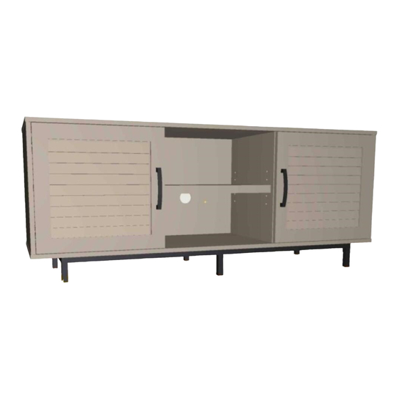
Page 7: Exploded Diagram
exploded diagram ITEM DESCRIPTION Top panel Back panel Left side panel Right side panel Left partition panel Right partition panel Left door Right door Bottom panel Support leg with leveler Bottom stretcher Large adjustable shelf Small adjustable shelf... - Page 8 190°-230°...
- Page 9 step 1: Combine the base NOTE: DO NOT fully tighten all bolts until you finish assembling all parts. Once assembled, go back and fully tighten all bolts. This will make the assembly easier. (H4) x 8 (H5) x 8 1/4” x 5/8” bolt lock washer (H6) x 8 (H13) x 1...
- Page 10 step 2: Screw-in cam bolts on the top panel (H2) x 8 cam bolt 2.1. Securely screw the cam bolts (H2) into the designated small holes on the top panel (A).
- Page 11 step 3. Attach side panels and partition panels to the top panel Finished edge C D E F (H1) x 8 (H3) x 8 cam lock M8 x 30 mm wood dowel Finished edge 3.1. Insert two wood dowels (H3) into the top inner holes of each side panels (C and D) and partition panels (E and F). 3.2.
- Page 12 step 4. Attach bottom panel to the vertical panels Door hinge mounting holes (H3) x 8 M8 x 30 mm wood dowel (H7) x 8 M4 x 50 mm screw The edge with the mounting holes for metal base running against located at back. 4.1.
- Page 13 step 5. Attach the base to the bottom panel CAUTION: Heavy! You may need assistance with this step. (H8) x 12 M4 x 32 mm screw 5.1. Ask for assistance to turn the unit upside down. 5.2. Align the mounting holes on the assembled base (J and K) with the pilot holes on the bottom panel (I). Attach using twelve 32 mm screws (H8) provided.
- Page 14 step 6. Attach the back panel to the frame CAUTION: Heavy! You may need assistance with this step. (H9) x 24 M3.5 x 15 mm washer head screw 6.1. With the help of another adult, flip the assembled unit around on its front edges. 6.2.
- Page 15 step 7. Attach hinges to the doors (H14) x 4 door hinge 7.1. Extend the hinges if necessary and rest the hinge cups (H14) onto the cutouts of the doors (G and H). 7.2. With the pilot holes as a guide, secure the door hinges (H14) into place by tightening the screws provided .
- Page 16 step 8. Fasten the handles to the doors (H16) x 2 (H17) x 4 handle 25 mm handle bolt 8.1. Attach one handle (H16) to the front side of each doors (G and H) using the handle bolts (H17) provided.
-
Page 17: Step 9. Install Doors
step 9. Install doors If you find that the doors need to be adjusted slightly, turn CAUTION: Heavy! You may the appropriate screw, as illustrated upper. need assistance with this step. 1. TO ADJUST THE DOOR FORWARD OR BACKWARD. 2. TO ADJUST THE DOOR TO RIGHT OR TO LEFT. 3. - Page 18 step 10. Install the adjustable shelves (H10) x 12 (H11) x 12 M3.5 x 12 mm screw shelf support 10.1. Insert four shelf supports (H11) into the desired holes in the sides of each compartment. Make sure you place the four shelf supports in the same level so the shelf is not tilted.
- Page 19 step 11. Install rubber bumpers and conceal the cams (H15) x 8 (H12) x 4 cam lock cover rubber bumper 11.1. Put two rubber bumpers (12) onto the front edge of each partition panels (E and F). 11.2. Plug the cam lock covers (H15) onto the visible cams locks to conceal the cams.
- Page 20 step 12. Install the tip-over restraint hardware kits Wooden stud Wall Short screw Wall (H18) x 2 tipping restraint hardware kit (inside plastic bag) Floor leveler Long screw Metal bracket Nylon strap Tools required: Phillips screwdriver, stud finder, tape measure, pencil, power drill and 1/8” drill bit (not provided). 12.1.
-
Page 21: Care And Maintenance
Care and Maintenance • Use a soft, clean cloth that will not scratch the surface when dusting. • Use of furniture polish is not necessary. Should you choose to use polish, test first in an inconspicuous area. • Using solvents of any kind on your furniture may damage the finish. •... - Page 22 The maximum recommended weight allowance is 36.3 kg / 80 lb for top surface. The maximum recommended weight allowance is 22.7 kg / 50 lb for shelves and bottom panel. Death or serious injury may occur when children climb on audio and/or video equipment furniture. A remote control or toys placed on the furnishing may encourage a child to climb on the furnishing and as a result may tip over onto the child.
Need help?
Do you have a question about the TGAVCL-13 and is the answer not in the manual?
Questions and answers