
Related Manuals for Threshold STUDIO McGEE Crystal Cove TGT60BK


Summary of Contents for Threshold STUDIO McGEE Crystal Cove TGT60BK
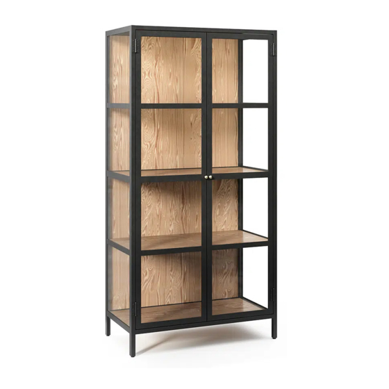
- Page 1 Crystal Cove 60" Glass Cabinet - Black Style # TGT60BK DPC-item # 249-17-0519 >> Assembly instructions © 2022 Target. The Bullseye Design is a trademark of Target Brands, Inc. All rights reserved.
-
Page 2: Before You Begin
Congratulations on your latest Target purchase. Now what? Don’t start sweating over this box of parts. This will be easy. We did the hard work for you. All you need to do is follow our simple instructions and you’ll be on your way to transforming your room in no time. Good luck –... - Page 3 FURNITURE TIPPING RESTRAINT YOUNG CHILDREN MAY BE INJURED BY TIPPING FURNITURE AND YOU MUST USE THIS TIPPING RESTRAINT TO ATTACH THIS UNIT TO THE WALL, TO PREVENT ACCIDENTS AND/OR INJURIES. TO PROVIDE PROTECTION AGAINST THE UNEXPECTED TIPPING OF FURNITURE DUE TO IMPROPER USE. USE OF TIP-OVER RESTRAINTS MAY ONLY REDUCE, BUT NOT ELIMINATE, THE RISK OF TIP-OVER.
- Page 4 hardware (H1) x 30 (H2) x 12 (H3) x 2 (H4) x 26 (H5) x 2 1/4” x 12 mm bolt M4 x 10 mm bolt knob bolt M4.5 x 15 mm knob pan head screw (H6) x 2 (H7) x 1 (H8) x 1 (H9) x 2 flat washer...
- Page 5 exploded diagram ITEM DESCRIPTION Top panel Left side frame Right side frame Left door Right door Middle / Bottom shelf Upper / Lower shelf Bottom front / Middle stretcher Bottom back stretcher Metal bracket Middle back panel Upper / Bottom back panel...
- Page 6 step 1: Attach the stretchers between the side frames NOTE: DO NOT fully tighten all bolts until you finish assembling all parts. Once assembled, go back and fully tighten all bolts. This will make the assembly easier. (H1) x 6 (H8) x 1 1/4”...
- Page 7 step 2: Fasten the top panel to the previous assembly NOTE: Try working from one end to the other to slide the top panel (A) into place. You may need to push or pull the top stretchers and side frames slightly to get them to align with the holes.
- Page 8 step 3: Attach the shelves to the unit (H4) x 26 M4.5 x 15 mm pan head screw 3.1. Tilt and slide the middle and bottom shelves (F) onto the metal tabs of both side frames (B and C) and the stretchers (H and I) as shown. 3.2.
- Page 9 step 4: Fit the set square onto the front corners for checking the unit square (H7) x 1 Jet square 4.1. Now, go back and tighten all bolts and screws. Make sure all the parts are tight and there are no gaps between the parts. This will help keep the unit square. 4.2.
- Page 10 step 5: Install the door knobs (H3) x 2 (H5) x 2 knob bolt knob 5.1. Fasten the knob (H5) to the front side of each doors (D and E ) with one knob bolt (H3) per knob.
- Page 11 step 6: Install the doors NOTE: DO NOT fully tighten all bolts until you finish assembling all parts. Once assembled, go back and fully tighten all bolts. This will make the assembly easier. (H2) x 12 M4 x 10 mm bolt The drainage hole will face the floor when the unit is turned upright.
- Page 12 step 7: Attach the metal bracket to the front stretcher of top panel Back view CAUTION: Heavy! You may need assistance with this step. NOTE: DO NOT fully tighten all bolts until you finish assembling all parts. The magnetic catch is located Once assembled, go back and fully at the front and tighten all bolts.
- Page 13 step 8: Fit the set square onto the back corners for checking the unit square (H7) x 1 Jet square 8.1. Fit the set square (H7) onto the back corners of the assembly for checking the unit square. If you find that there are gaps and no square between the parts, this can be done by loosening the installed bolts and adjust properly for a good fit.
- Page 14 step 9: Fasten the back panels to the unit CAUTION: Heavy! You may need assistance with this step. (H1) x 18 (H6) x 2 (H8) x 1 1/4” x 12 mm bolt flat washer hex wrench 9.1. Make sure the front doors, both left (D) and right (E), are aligned and with equal gaps, doors touching the magnetic catch. Align the levelers if required. 9.2.
- Page 15 step 10: Attach tip-over restraint hardware kit Wooden stud Nylon strap Bolt Wall Wall (H9) x 2 tipping restraint hardware kit (inside plastic bag) Metal bracket Long screw Floor leveler Tools required: Phillips screwdriver, stud finder, tape measure, pencil, power drill and 1/8” drill bit. 10.1.
- Page 16 step 11: Correct the doors alignment Floor leveler NOTE: Open and close the doors and adjust the gaps to make sure they are aligned and shut correctly. If you find that the doors do not close properly or do not align correctly, please follow these steps: 11.1.
-
Page 17: Care And Maintenance
Care and Maintenance Use a soft, clean cloth that will not scratch the surface when dusting. Use of furniture polish is not necessary. Should you choose to use polish, test first in an inconspicuous area. Using solvents of any kind on your furniture may damage the finish. ... - Page 18 The shelf, top and bottom panel maximum recommended weight allowance is 22.7 kg / 50 lb. Death or serious injury may occur when children climb on audio and/or video equipment furniture. A remote control or toys placed on the furnishing may encourage a child to climb on the furnishing and as a result may tip over onto the child. NEVER allow children to climb or play with the TV or furnishing supporting the TV.
Need help?
Do you have a question about the STUDIO McGEE Crystal Cove TGT60BK and is the answer not in the manual?
Questions and answers