Advertisement
Quick Links
Advertisement

Related Manuals for Threshold TGAVC72-23


Summary of Contents for Threshold TGAVC72-23
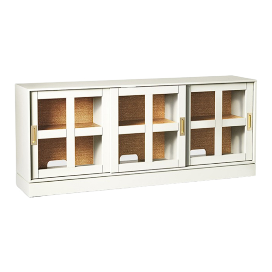
- Page 1 Promontory 72" Sliding Glass Media Stand Style # TGAVC72-23 DPC-item #: 249-10-5786 (White) Style # TGAVC72-24 DPC-item #: 249-10-8938 (Black) >> Assembly instructions © 2023 Target. The Bullseye Design is a trademark of Target Brands, Inc. All rights reserved.
-
Page 2: Before You Begin
Congratulations on your latest Target purchase. Now what? Don’t start sweating over this box of parts. This will be easy. We did the hard work for you. All you need to do is follow our simple instructions and you’ll be on your way to transforming your room in no time. Good luck –... - Page 3 (H4) x 12 (H5) x 16 cam lock cam bolt M8 x 30 mm shelf support white cam lock cover (TGAVC72-23) wood dowel black cam lock cover (TGAVC72-24) (H6) x 8+1 (H7) x 12 (H8) x 4 (H9) x 2...
- Page 4 exploded diagram ITEM DESCRIPTION Top panel Left / Right adjustable shelf Base Middle partition Left sliding door Middle / Right sliding door Back panel Side panel Middle adjustable shelf...
-
Page 5: How To Use The Cam Lock System
how to use the cam lock system Push cam into panel - arrow Align cam bolt(s) with cam(s) Screw cam bolt into panel feature on cam top points to and insert all the way into panel edge cross-bored hole(s) 190°-230° Panels should be tight against Rotate cam(s) clockwise each other and connection... - Page 6 step 1: prepare the top panel, side panels and base assembly (H2) x 36 cam bolt 1.1. Securely screw the cam bolts (H2) into the designated small holes on the top panel (A), the base (C) and the side panels (H).
- Page 7 step 2: attach the back panel between the side panels The cam locks face inward (H1) x 8 (H3) x 4 cam lock M8 x 30 mm wood dowel 2.1. Insert four 30mm wood dowels (H3) into the side holes of the back panels (G) at both ends. 2.2.
- Page 8 step 3: attach the previous assembly to the base Floor leveler (H1) x 10 (H3) x 8 cam lock M8 x 30 mm wood dowel The floor protector 3.1. Insert eight 30mm wood dowels (H3) into the bottom inner holes of the panels (H and G). 3.2.
- Page 9 step 4: attach the middle partitions to the base (H1) x 4 (H3) x 4 cam lock M8 x 30 mm wood dowel 4.1. Insert two 30mm wood dowels (H3) into the bottom inner holes of each middle partition (D). 4.2.
- Page 10 step 5: attach the top panel to the previous assembly (H1) x 14 (H3) x 12 cam lock M8 x 30 mm wood dowel 5.1. Insert twelve 30mm wood dowels (H3) into the top inner holes of the panels (D, G and H). 5.2.
- Page 11 step 6: fasten the back panels NOTE: DO NOT use power tools. (H8) x 4 M4 x 35 mm screw 6.1. With the help of another adult, stand the unit upright. 6.2. Fasten the back panels (G) to the middle partitions (D) with four 35mm screws (H8).
- Page 12 step 7: install the adjustable shelves (H4) x 12 (H7) x 12 shelf support M3.5 x 12 mm screw 7.1. Insert four shelf supports (H4) into the desired holes in the sides of each compartment. Make sure you place the four shelf supports at the same level so the shelf is not tilted.
- Page 13 step 8: install the sliding doors Guide pin Lever Door inner view Lever NOTE: The guide pins are retracted and flush with the door top rail when shipping. If the guide pins accidentally protruded out (the lever is unlocked) when assembly, press them down from the top and proceed with the assembly.
- Page 14 9: Install the cam lock covers and rubber bumpers NOTE: DO NOT slam shut the sliding doors to prevent from damaging and leaving gap. (H5) x 16 white cam lock cover (TGAVC72-23) black cam lock cover (TGAVC72-24) (H6) x 8+1 (H10) x 20 rubber bumper brown cam lock cover 9.1.
- Page 15 step 10: install the tipping restraint hardware kit Wooden stud Wall Short screw Wall (H9) x 2 tipping restraint hardware kit Floor leveler Metal bracket Nylon strap Long screw Tools required: Phillips screwdriver, stud finder, tape measure, pencil, power drill and 1/8” drill bit (not provided). 10.1.
- Page 16 FURNITURE TIPPING RESTRAINT YOUNG CHILDREN MAY BE INJURED BY TIPPING FURNITURE AND YOU MUST USE THIS TIPPING RESTRAINT TO ATTACH THIS UNIT TO THE WALL, TO PREVENT ACCIDENTS AND/OR INJURIES. TO PROVIDE PROTECTION AGAINST THE UNEXPECTED TIPPING OF FURNITURE DUE TO IMPROPER USE. USE OF TIP-OVER RESTRAINTS MAY ONLY REDUCE, BUT NOT ELIMINATE, THE RISK OF TIP-OVER.
-
Page 17: Care And Maintenance
Care and Maintenance Use a soft, clean cloth that will not scratch the surface when dusting. Use of furniture polish is not necessary. Should you choose to use polish, test first in an inconspicuous area. Using solvents of any kind on your furniture may damage the finish. ... - Page 18 M A X I M U M R E C O M M E N D E D W E I G H T L O A D S MANUFACTURER: Whalen Furniture Manufacturing CATALOG: Promontory 72" Sliding Glass Media Stand MODEL # TGAVC72-23, TGAVC72-24 FITS UP TO MOST 188 cm / 74 in. DIAGONAL FLAT-PANEL TVS MAXIMUM LOAD 54.4 kg / 120 lb...
- Page 19 The maximum recommended weight allowance is 54.4 kg / 120 lb for top panel. The maximum recommended weight allowance is 22.7 kg / 50 lb for shelves. This unit is not intended for use with CRT TVs. The top surface maximum weight capacity is 120 lb (54.4 kg) and maximum load 74 in.
Need help?
Do you have a question about the TGAVC72-23 and is the answer not in the manual?
Questions and answers