
Related Manuals for Threshold TGT15FC


Summary of Contents for Threshold TGT15FC
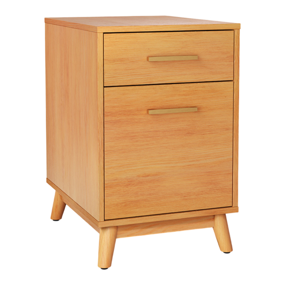
- Page 1 2-Drawer File Cabinet Style # TGT15FC DPC-item #: 081-07-7161 >> Assembly instructions © 2022 Target. The Bullseye Design is a trademark of Target Brands, Inc. All rights reserved.
- Page 2 Congratulations on your latest Target purchase. Now what? Don’t start sweating over this box of parts. This will be easy. We did the hard work for you. All you need to do is follow our simple instructions and you’ll be on your way to transforming your room in no time. Good luck –...
- Page 3 hardware (H1) x 18 (H2) x 8 (H3) x 26 (H4) x 8 (H5) x 18 large cam lock small cam lock cam bolt M6 x 30 mm wood dowel M8 x 30 mm wood dowel (H6) x 8 (H10) x 4 (H7) x 8 (H8) x 8 (H9) x 8...
- Page 4 exploded diagram ITEM DESCRIPTION Top panel Left side panel Right side panel Back panel Bottom panel Utility drawer front panel Utility drawer back panel Utility drawer left side panel Utility drawer right side panel Utility drawer bottom panel Front crossbar File drawer front panel File drawer back panel File drawer left side panel...
- Page 5 how to use the cam lock system Push cam into panel - arrow Align cam bolt(s) with cam(s) Screw cam bolt into panel feature on cam top points to and insert all the way into panel edge cross-bored hole(s) 190°-230° Panels should be tight against Rotate cam(s) clockwise each other and connection...
- Page 6 step 1: prepare drawers assembly NOTE: Screw-in cam bolts must be NOTE: Screw-in cam bolts must be screwed down flush. screwed down flush. (H3) x 8 cam bolt 1.1. Securely screw the cam bolts (H3) into the designated small holes on the drawer front panels (F and L).
- Page 7 step 2: attach the utility drawer side panels The grooves line up with each other and face inward (H2) x 4 small cam lock 2.1. Attach the utility drawer side panels (H and I) to the utility drawer front panel (F) with four small cam locks (H2).
- Page 8 step 3: install the utility drawer bottom panel 3.1. Slide the utility drawer bottom panel (J) into the grooves between the drawer side panels (H and I) until fully inserted into the groove of the drawer front panel (F).
- Page 9 step 4: fasten the utility drawer back panel NOTE: Make sure that the drawer bottom panel (J) fits securely into the groove of the drawer back panel (G). DO NOT use power tools. (H9) x 4 M4 x 32 mm screw 4.1.
- Page 10 step 5: install the utility drawer handle (H10) x 2 (H11) x 1 22 mm handle bolt handle 5.1. Fasten one handle (H11) to the front side of the utility drawer front panel (F) with two 22 mm handle bolts (H10).
- Page 11 step 6: attach the file drawer side panels The grooves line up with NOTE: DO NOT use power tools. each other and face inward FINAL (H4) x 4 (H9) x 4 M6 x 30 mm wood dowel M4 x 32 mm screw 6.1.
- Page 12 step 7: install the file drawer bottom panel 7.1. Slide the file drawer bottom panel (P) into the grooves between the drawer side panels (N and O) until fully inserted into the groove of the drawer back panel (M).
- Page 13 step 8: attach the file drawer front panel (H2) x 4 (H4) x 4 small cam bolt M6 x 30 mm wood dowel 8.1. Insert four small wood dowels (H4) into the inner holes on the two file drawer side panels (N and O). 8.2.
- Page 14 step 9: install the file drawer handle (H10) x 2 (H11) x 1 22 mm handle bolt handle 9.1. Fasten the other handle (H11) to the front side of the file drawer front panel (L) with two 22 mm handle bolts (H10).
- Page 15 step 10: position the guide rails and file hangers 10.1. Position the guide rails (Q) onto the file drawer side panels (N and O) with the high side facing inward. 10.2. Hook the guide blocks of the file hangers (R) onto the high edge of the guide rails (Q). Slide the file hanger forward and backward to keep hanging files organized.
- Page 16 step 11: attach the feet NOTE: DO NOT fully tighten all the bolts until you adjusted to even all the feet. (H6) x 8 (H7) x 8 1/4” x 45 mm bolt lock washer (H8) x 8 (H12) x 1 flat washer hex wrench 11.1.
- Page 17 step 12: prepare top panel and base assembly NOTE: Screw-in cam bolts must be screwed down flush. (H3) x 12 cam bolt 12.1. Securely screw the cam bolts (H3) into the designated small holes on the top panel (A) and bottom panel (E).
- Page 18 step 13: prepare side panels assembly NOTE: Screw-in cam bolts must be screwed down flush. (H3) x 6 cam bolt 13.1. Securely screw the cam bolts (H3) into the designated small holes on the side panels (B and C).
- Page 19 step 14: install file cabinet frame The cam lock will face the floor when the unit is turned upright (H1) x 6 (H5) x 6 large cam lock M8 x 30 mm wood dowel 14.1. Insert four large wood dowels (H5) into the inner holes of the back panel (D) at both long ends. 14.2.
- Page 20 step 15: attach the top panel (H1) x 6 (H5) x 6 large cam lock M8 x 30 mm wood dowel 15.1. Insert six large wood dowels (H5) into the top inner holes on both side panels (B and C) and the back panel (D). 15.2.
- Page 21 step 16: attach the bottom panel (H1) x 6 (H5) x 6 large cam lock M8 x 30 mm wood dowel 16.1. Insert six large wood dowels (H5) into the bottom inner holes on both side panels (B and C) and the back panel (D). 16.2.
- Page 22 step 17: install the drawers Ball bearing cart Ball bearing cart Release lever Release lever Drawer installation 17.1. Now, go back and tighten all cam locks and screws. Make sure all the parts are tight and there are no gaps between the parts. This will help keep the unit square.
- Page 23 step 18: adjust floor levelers Floor leveler 18.1. Adjust the floor levelers pre-attached at the bottom of the feet (S) to level the unit against a wall.
- Page 24 step 19: install the tipping restraint hardware kit Wooden stud Connector Wall Short screw Wall (H13) x 1 tipping restraint hardware kit (inside plastic bag) Metal bracket Long screw Steel cable Tools required: Phillips screwdriver, stud finder, tape measure, pencil, power drill and 1/8” drill bit (not provided). 19.1.
- Page 25 Care and Maintenance · Use a soft, clean cloth that will not scratch the surface when dusting. · Use of furniture polish is not necessary. Should you choose to use polish, test first in an inconspicuous area. · Using solvents of any kind on your furniture may damage the finish. ·...
- Page 26 M A X I M U M R E C O M M E N D E D W E I G H T L O A D S MANUFACTURER: Whalen Furniture Manufacturing CATALOG: 2-Drawer File Cabinet MODEL # TGT15FC MAXIMUM LOAD 22.7 kg / 50 lb MAXIMUM LOAD 4.5 kg / 10 lb MAXIMUM LOAD 13.6 kg / 30 lb...
- Page 27 The maximum recommended weight allowance is 22.7 kg / 50 lb for the top. The maximum recommended weight allowance is 4.5 kg / 10 lb for the utility drawer. The maximum recommended weight allowance is 13.6 kg / 30 lb for the file drawer. Death or serious injury may occur when children climb on audio and/or video equipment furniture.
- Page 28 FURNITURE TIPPING RESTRAINT YOUNG CHILDREN MAY BE INJURED BY TIPPING FURNITURE AND YOU MUST USE THIS TIPPING RESTRAINT TO ATTACH THIS UNIT TO THE WALL, TO PREVENT ACCIDENTS AND/OR INJURIES. TO PROVIDE PROTECTION AGAINST THE UNEXPECTED TIPPING OF FURNITURE DUE TO IMPROPER USE. USE OF TIP-OVER RESTRAINTS MAY ONLY REDUCE, BUT NOT ELIMINATE, THE RISK OF TIP-OVER.
Need help?
Do you have a question about the TGT15FC and is the answer not in the manual?
Questions and answers