Table of Contents
Advertisement
Quick Links
Advertisement
Table of Contents

Related Manuals for DFI ADS310-R680E/Q670E


Summary of Contents for DFI ADS310-R680E/Q670E
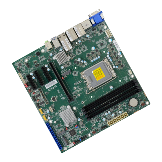
- Page 1 ADS310-R680E/Q670E microATX Industrial Motherboard User’s Manual...
- Page 2 1. The changes or modifications not expressly approved by the party responsible for com- are the properties of the respective owners. pliance could void the user’s authority to operate the equipment. 2. Shielded interface cables must be used in order to comply with the emission limits. User's Manual | ADS310-R680E/Q670E...
-
Page 3: Table Of Contents
CPU Configuration ......................35 Power & Performance ....................35 Power & Performance ► CPU- Power Management Control ......36 Power & Performance ► GT- Power Management Control ......... 37 PCH-FW Configuration ....................38 Trusted Computing ......................39 NCT6126D Super IO Configuration ................39 User's Manual | ADS310-R680E/Q670E... - Page 4 • To reduce the risk of electric shock, unplug the power cord before removing the sys- tem chassis cover for installation or servicing. After installation or servicing, cover the system chassis before plugging the power cord. User's Manual | ADS310-R680E/Q670E...
- Page 5 The package contains the following items. If any of these items are missing or damaged, please contact your dealer or sales representative for assistance. • 1 ADS310-R680E/Q670E motherboard • 1 COM port cable (Length: 300mm, 2 x COM ports) • 1 Serial ATA data cable (Length: 500mm) •...
-
Page 6: Chapter 1 - Introduction
1 x M.2 2242/2260/2280 M key (PCIe x4 Gen4 NVMe) 1 x M.2 2242/2260/2280 M key (PCIe x4 Gen4 NVMe/SATA) 1 x M.2 2230 E key (PCIe/USB 2.0/Intel CNVi support) (Discrete Wifi 6E support) User's Manual | ADS310-R680E/Q670E AUDIO Audio Codec... - Page 7 RAID 0/1/5/10 PS/2 1 x PS/2 (2.54mm pitch) 1 x 8-bit DIO SMBus 1 x SMBus WATCHDOG Output & System Reset, Programmable via Software from 1 to 255 Seconds TIMER Interval SECURITY Nuvoton TPM 2.0 www.dfi.com User's Manual | ADS310-R680E/Q670E...
- Page 8 Active -5 to 65°C 8-pin ATX 12V PACKING LIST OPTIONAL ITEMS User's Manual | ADS310-R680E/Q670E 1 ADS310-R680E/Q670E motherboard USB 2.0 port cable (Length: 350/398mm) A81-001066-016G 1 COM port cable (Length: 300mm, 2 x COM ports) A81-015026-023G USB 3.2 Gen2 port cable (Length: 350mm)
-
Page 9: Features
Plug and Play peripherals. RTC Timer The Real Time Clock (RTC) installed on the system board allows your system to automatically power-on on the set date and time. User's Manual | ADS310-R680E/Q670E... -
Page 10: Block Diagram
Chapter 1 INTRODUCTION X Block Diagram User's Manual | ADS310-R680E/Q670E... -
Page 11: Chapter 2 - Hardware Installation
PCIE3 (PCIe x4) JP33 USB3_5/6 JP32 USB2_5/6 M.2 M Key TSJP3 TSJP8 TSJP6 Front Audio M2CN3 PCIE4 (PCIe x4) M.2 E Key TSJP4 TSJP2 TSJP7 M2CN2 TSJP5 TSJP1 JP29/30/28 S/PDIF SYS_FAN1 COM1 COM2 USB2_13 SATA0(R4)/SATA1(R5)/SATA2(R6)/SATA3(R7) Power USB2_11/12 User's Manual | ADS310-R680E/Q670E... -
Page 12: System Memory
Data will be accessed in chunks of 128 bits from the memory channels. Dual channel provides better system performance because it doubles the data transfer rate. Features • Four 288-pin UDIMM up to 128GB • Dual Channel DDR4 3200MHz (ECC support: R680E only) User's Manual | ADS310-R680E/Q670E... -
Page 13: Removing The Dimm Module
The tabs snap automatically to the edges of the card and lock the card in place. Hold the card by its edges and remove it from the slot. Step 1 Step 1 Step 2 Step 2 Step 3 Step 3 User's Manual | ADS310-R680E/Q670E... -
Page 14: Cpu
Align the 4 screw holes and tighten the heat sink up by inserting screws, DO remember to con- nect the fan cable on the board. (The location of fan connector may vary.) There are 4 screw holes around the CPU for the heat sink to be mounted. User's Manual | ADS310-R680E/Q670E... -
Page 15: Jumper Settings
2. Put a jumper cap on pin 2 and pin 3. Wait for a few seconds and set it back to its de- fault setting, i.e. jumper cap on pin 1 and pin 2. 3. Plug the power cord and power-on the system. „ 1-2 On: Normal (default) „ 2-3 On: Clear CMOS Data User's Manual | ADS310-R680E/Q670E... -
Page 16: Dio Power & Voltage - Jp28/29/30
JP28 „ 1-2 On: 5VDU (default) „ 2-3 On: 5V „ 1-2 On: „ 2-3 On: Control by BIOS (default) Wake up disable JP29 (DIO0~3) JP30 (DIO4~7) „ 1-2 On: 5V_DIO (default) „ 2-3 On: GND User's Manual | ADS310-R680E/Q670E... -
Page 17: Connector Power Control - Jp31/Jp32/Jp33
„ 2-3 On: 3V3DU JP33 is used to control the power of M.2 E Key (M2CN2). „ 1-3, 2-4 On: „ 3-5, 4-6 On: RS232 Standard (default) RS232 with Power „ 2-3 On: 3V3 „ 1-2 On: 3V3DU (default) User's Manual | ADS310-R680E/Q670E... -
Page 18: Selection For Com1 / Com2 - Tsjp4,3,2 / Tsjp8,7,6
„ 3-5, 4-6 On: RS232 (default) RS422 RS485 TSJP4,3,2 and TSJP8,7,6 are used to determine the signal type of COM1/COM2. TSJP2(COM1), TSJP6(COM2) „ 1-3, 4-6 On: „ 3-5, 4-6 On: „ 3-5, 2-4 On: RS232 (default) RS422 RS485 User's Manual | ADS310-R680E/Q670E... -
Page 19: At/Atx Select - Jp26
PCIE4 (PCIe x4) M.2 E Key TSJP4 TSJP2 TSJP7 M2CN2 TSJP1 TSJP5 JP29/30/28 S/PDIF SYS_FAN1 COM1 COM2 USB2_13 Power SATA0(R4)/SATA1(R5)/SATA2(R6)/SATA3(R7) USB2_11/12 JP26 switches the AT/ATX mode. „ 1-2 On: „ 2-3 On: AT Mode(default) ATX Mode User's Manual | ADS310-R680E/Q670E... -
Page 20: Rear I/O Ports
• 2.5G LAN 1/2 • 1 HDMI port • 1 VGA port • 10G LAN 1/2 • 4 USB 3.2 Gen 1 ports • 1 Line-in jack (optional) • 1 Line-out jack • 1 Mic-in jack User's Manual | ADS310-R680E/Q670E... -
Page 21: Usb Ports
S3 (STR - Suspend To RAM) state. • 4 x USB 3.2 Gen 1 rear ports (USB 7/8/9/10) • 2 x USB 2.0 internal ports, box headers (USB 11/12) • 1 x USB 2.0 internal ports, (USB 13) User's Manual | ADS310-R680E/Q670E... -
Page 22: Graphics Interfaces
The VGA port is used for connecting a VGA monitor. Connect the monitor’s 15-pin D-shell cable connector to the VGA port. After you plug the monitor’s cable connector into the VGA port, gen- tly tighten the cable screws to hold the connector in place. User's Manual | ADS310-R680E/Q670E... -
Page 23: Lan Ports
Mic-in Jack (Pink) This jack is used to connect an external microphone. Front Audio The front audio connector allows you to connect to the second line-out and mic-in jacks that are at the front panel of your system. User's Manual | ADS310-R680E/Q670E... -
Page 24: Internal I/O Connectors
• 4 Serial ATA 3.0 ports with data transfer rate up to 6Gb/s D_IOA3 • Integrated Advanced Host Controller Interface (AHCI) controller D_IOA4 • Support RAID 0, RAID 1, RAID 5, RAID 10 D_IOA5 D_IOA6 D_IOA7 User's Manual | ADS310-R680E/Q670E... -
Page 25: Cooling Fan Connectors
Insufficient power supplied to the system may result in instability or malfunction of the add-in boards and peripherals. Calculating the system’s approximate power Control usage is important to ensure that the power supply meets the system’s consump- tion requirements. User's Manual | ADS310-R680E/Q670E... -
Page 26: Front Panel
Power On Suspend) state, it will blink at 1-second intervals. When the system is in the S3 (STR - Suspend To RAM) state, it will blink at 4-second intervals. Power Button This button is used to switch the system's power on or off . User's Manual | ADS310-R680E/Q670E... -
Page 27: Com1
COM2 USB2_13 Power SATA0(R4)/SATA1(R5)/SATA2(R6)/SATA3(R7) Power SATA0(R4)/SATA1(R5)/SATA2(R6)/SATA3(R7) USB2_11/12 USB2_11/12 Pin Assignment Pin Assignment Pin Assignment Assignment X_MDCD1- MSIN1- COM X_MDCD2- MSIN2- COM MSO1- COM MDTR1- COM MSO2- COM MDTR2- COM MDSR1- MDSR2- MRTS1- MCTS1- MRTS2- MCTS2- X_MRI1- X_MRI2- User's Manual | ADS310-R680E/Q670E... -
Page 28: Front Audio
COM2 USB2_13 Power SATA0(R4)/SATA1(R5)/SATA2(R6)/SATA3(R7) Power SATA0(R4)/SATA1(R5)/SATA2(R6)/SATA3(R7) USB2_11/12 USB2_11/12 Pin Assignment Pin Assignment Pin Assignment Pin Assignment MIC2-L A_GND LED_SPEED_2500# LED_SPEED_1000# GBE_LED_LINK_ MIC2-R 3V3DU ACT# LED_ LED_ LINE2-R MIC2-JD SPEED_2500#_2 SPEED_1000#_2 GBE_LED_LINK_ A_GND 3V3DU ACT#_2 LINE2-L LINE2-JD User's Manual | ADS310-R680E/Q670E... -
Page 29: Usb 3.2 Gen2 Key B
COM2 USB2_13 Power SATA0(R4)/SATA1(R5)/SATA2(R6)/SATA3(R7) SATA0(R4)/SATA1(R5)/SATA2(R6)/SATA3(R7) Power USB2_11/12 USB2_11/12 Pin Assignment Assignment Pin Assignment Assignment USB3_TX5_DP USB3_TX6_DN PS2_KCLK PS2_MCLK USB3_TX5_DN USB3_TX6_DP PS2_KDAT PS2_MDAT USB3_RX5_DP USB3_RX6_DN USB3_RX5_DN USB3_RX6_DP PS/2 POWER PS/2 POWER USBP_C_5P USBP_C_6P USBP_C_5N USBP_C_6N SBV3 SBV3 User's Manual | ADS310-R680E/Q670E... -
Page 30: Usb 2.0 (Usb2 11/12/13)
„ USB 2.0 13 „ USB 2.0 11/12 „ USB 2.0 11/12 „ USB 2.0 13 Pin Assignment Pin Assignment Pin Assignment Pin Assignment Pin Assignment Pin Assignment 3V3DU SBV6 SBV6 SBV6 SBV6 SMB_CLK SMB_DATA USBP_C_11N USBP_C_12N USBP_C_13N SMB_ALERT- USBP_C_11P USBP_C_12P USBP_C_13P User's Manual | ADS310-R680E/Q670E... -
Page 31: Expansion Slots
Install PCI Express cards such as network cards or other expansion cards M.2 Socket The M.2 socket is the Next Generation Form Factor (NGFF) which is designed to support mul- tiple modules and make the M.2 more suitable in application for solid-state storage. User's Manual | ADS310-R680E/Q670E... -
Page 32: Battery
• There exists explosion hazard if the battery is incorrectly installed. card should be lying parallel to the board when it’s correctly • Replace only with the same or equivalent type recommended by the manufacturer. mounted. • Dispose of used batteries according to local ordinances. User's Manual | ADS310-R680E/Q670E... -
Page 33: Chapter 3 - Bios Settings
“Press DEL to run setup” will appear on the screen. If the message disappears before you respond, restart the system or press the “Reset” button. You may also restart the system by pressing the <Ctrl> <Alt> and <Del> keys simultaneously. User's Manual | ADS310-R680E/Q670E... -
Page 34: Main
The time format is <hour>, <minute>, <second>. The time is based on the 24-hour military-time clock. For example, 1 p.m. is 13:00:00. Hour displays hours from 00 to 23. Minute displays min- utes from 00 to 59. Second displays seconds from 00 to 59. User's Manual | ADS310-R680E/Q670E... -
Page 35: Cpu Configuration
Enables this field for Windows XP and Linux which are optimized for Hyper-Threading technol- ogy. Select disabled for other OSes not optimized for Hyper-Threading technology. When dis- abled, only one thread per enabled core is enabled. Enable / Disable AES (Advanced Encryption Standard) User's Manual | ADS310-R680E/Q670E... -
Page 36: Power & Performance ► Cpu- Power Management Control
Enable or disable turbo mode of the processor. This field will only be displayed when EIST is enabled. Configure Turbo Options Configure Turbo Options. C states Enable or disable CPU Power Management. It allows CPU to enter "C states" when it’s idle and nothing is executing. User's Manual | ADS310-R680E/Q670E... -
Page 37: Power & Performance ► Gt- Power Management Control
Chapter 3 BIOS SETTINGS Advanced Power & Performance ► GT- Power Management Control RC6 (Render Standby) Check to enable render standby support. User's Manual | ADS310-R680E/Q670E... -
Page 38: Pch-Fw Configuration
MEBx Setup. This option does not disable manageability features in FW. ME Unconfig on RTC Clear When disabled, ME will not be unconfigured on RTC Clear. Firmware Update Configuration Configure Management Engine Technology Parameters. Note: The sub-menus are detailed in following sections. User's Manual | ADS310-R680E/Q670E... -
Page 39: Trusted Computing
This field is used to enable or disable BIOS support for the security device such as an TPM 2.0 to achieve hardware-level security via cryptographic keys. Pending Operation Schedule an Operation for the security Device. Note: Your computer will reboot udring restart in order to change state of security device. User's Manual | ADS310-R680E/Q670E... -
Page 40: Nct6126D Super Io Configuration Nct6126D Hw Monitor
This section displays the system’s health information, i.e. voltage readings, CPU and system temperatures, and fan speed readings Smart Fan Function Smart Fan Function Setting. Case Open Enable or disable the case open detection function. Serial Port Enable or disable serial port. User's Manual | ADS310-R680E/Q670E... -
Page 41: It8786 Hw Monitor ► Smart Fan Function
Fan Speed Count 1 field. • Fan Speed Count 1 to Fan Speed Count 4 Set the fan speed, the value ranging from 1-100%, 100% being full speed. The fans will operate according to the specified boundary temperatures above-mentioned. User's Manual | ADS310-R680E/Q670E... -
Page 42: Console Redirection Settings
Enable VT-UTF8 Combination Key Support for ANSI/VT100 terminals. Recorder Mode With this mode enbaled only text will be sent. This is to capture Terminal data. Resolution 100x31 Enables or disables extended terminal resolution Putty KeyPad Select FunctionKey and KeyPad on Putty. User's Manual | ADS310-R680E/Q670E... -
Page 43: Serial Port Console Redirection Acpi Settings
(G3 state). • S0 State The system automatically powers on after power failure. • S5 State The system enter soft-off state after power failure. Power-on signal input is required to power up the system. User's Manual | ADS310-R680E/Q670E... -
Page 44: Usb Configuration
Set the wait time in seconds to press ESC key to abort the PXE boot. Use either +/- or nu- meric keys to set the value. Media detect count Set the number of times the presence of media will be checked. Use either +/- or numeric keys to set the value. User's Manual | ADS310-R680E/Q670E... -
Page 45: Network Stack Configuration
USB Power Control DFI WDT Configuration Server CA Configuration Watchdog Timer 5_Dual: Support system wake up from S3/S4 by USB KB&MS Enable or disable Watchdog Timer. 5V: No support system wake up from S3/S4 by USB KB&MS User's Manual | ADS310-R680E/Q670E... -
Page 46: Dfi Wdt Configuration
Chapter 3 BIOS SETTINGS Advanced Tls Auth Configuration Server CA Configuration Press <Enter> to configure Server CA. User's Manual | ADS310-R680E/Q670E... -
Page 47: Tls Auth Configuration
System Agent (SA) Configuration Please select a submenu and press Enter. The submenus are detailed in the following pages. Graphics Configuration Settings about graphic. VMD setup menu VMD Configuration Settings PCI Express Configuration : VT-d VT-d capability. User's Manual | ADS310-R680E/Q670E... -
Page 48: Chipset
Select one of the PCI Express channels and press enter to configure the following settings. PCI Express Configuration Settings LAN1, LAN2, M.2-E, M.2-M2, PCIE2, PCIE3, PCIE4, SATA Configuration Control the PCI Express Root Port. SATA Device Otpions Settings HD Audio Configuration HD Audio Subsystem Configuration Settings User's Manual | ADS310-R680E/Q670E... -
Page 49: Pch-Io Configuration
This field is used to select SATA speed generation limit: Auto, Gen1, Gen2 or Gen3. Ports and Hot Plug • Enabled HDA will be unconditionally enabled. Enable or disable the Serial ATA port and its hot plug function. User's Manual | ADS310-R680E/Q670E... -
Page 50: Configuration► Sata Configuration
Clear the database from the NVRAM, including all the keys and signatures installed in the Key Management menu. Press Enter and a prompt will show up for you to confirm. Key Management Enables expert users to modify Secure Boot Policy variables without full authentication. User's Manual | ADS310-R680E/Q670E... -
Page 51: Security
• Restore Setting from file This field will appear only when a USB flash device is detected. Select tion. Refer to the Advanced > CSM Configuration submenu for more information. this field to restore set-ting from the USB flash device. User's Manual | ADS310-R680E/Q670E... -
Page 52: Boot
Chapter 3 BIOS SETTINGS X MEBx User's Manual | ADS310-R680E/Q670E... -
Page 53: Mebx
MAC address should be burned or not. c. After updating unique MAC Address from manufacturing, NVM will be protected immediately after power cycle. Users cannot update NVM or MAC address. User's Manual | ADS310-R680E/Q670E...
Need help?
Do you have a question about the ADS310-R680E/Q670E and is the answer not in the manual?
Questions and answers