Advertisement
Quick Links
Advertisement

Subscribe to Our Youtube Channel
Related Manuals for DFI ADS103


Summary of Contents for DFI ADS103
- Page 1 ADS101_ADS103 Thin Mini-ITX Industrial Motherboard User’s Manual © August 28, 2024 DFI Inc.
- Page 2 Copyright FCC and DOC Statement on Class B This publication contains information that is protected by copyright. No part of it may be repro- This equipment has been tested and found to comply with the limits for a Class B digital duced in any form or by any means or used to make any transformation/adaptation without the device, pursuant to Part 15 of the FCC rules.
- Page 3 Serial Port Console Redirection ► Console Redirection Settings ......32 ACPI Settings .........................33 Network Stack Configuration..................34 NVMe Configuration ......................35 DFI WDT Configuration ....................35 USB Power Control ......................36 Tls Auth Configuration ....................36 Chipset ..........................37 PEG Bifurcation ......................37 System Agent (SA) Configuration ................38 System Agent (SA) Configuration►...
- Page 4 About this Manual Static Electricity Precautions This manual can be downloaded from the website. It is quite easy to inadvertently damage your PC, system board, components or devices even before installing them in your system unit. Static electrical discharge can damage computer The manual is subject to change and update without notice, and may be based on editions that components without causing any signs of physical damage.
- Page 5 When installing the system board in a new system, you will need at least the following internal please contact your dealer or sales representative for assistance. components. • Memory module • 1 ANS101/ADS103 Motherboard • Storage device such as a hard disk drive. • 1 Serial ATA data & power cable w/lock (Length: 300mm) •...
- Page 6 Chapter 1 INTRODUCTION Chapter 1 - Introduction X Specifications SYSTEM Processor 14th Generation Intel LGA 1700 Socket Processors, TDP support up to 65W ® Intel Core™ I9-14900 (24 Cores, 36M Cache, up to 5.8 GHz); 65W ® Intel Core™ I9-14900T (24 Cores, 36M Cache, up to 5.5 GHz); 35W ®...
- Page 7 DP++: resolution up to 4096x2304 @60Hz LVDS: resolution up to 1920x1200 @ 60Hz eDP: resolution up to 4096x2160 @ 60Hz Quad Displays DP++ + DP++/HDMI + LVDS/eDP + DFI display extension port (DP/HDMI/VGA available) EXPANSION Interface 1 x PCIe x16 (Gen 5) (Max. 75W) 1 x M.2 2230 E Key (USB/PCIe x1)
- Page 8 System Reset, Programmable via Software from 1 to 255 Seconds SECURITY dTPM2.0 POWER Type Single 12V +/-10% DC (ADS101) Wide Range 15~36V (ADS103) Connector DC-in Jack Right Angle Connector (4-pin) (available upon request) Straight Type Connector (4-pin) (available upon request) Consumption Idle: i9-13900E 65W: 24V @ 3.14A (75.36W), 12V @ 5.52A (66.24W)
- Page 9 Chapter 1 INTRODUCTION X Dimension X Block Diagram User's Manual | ADS101_ADS103...
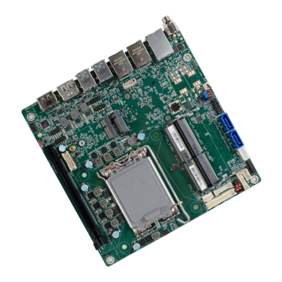
- Page 10 Chapter 2 HARDWARE INSTALLATION Chapter 2 - Hardware Installation X Board Layout DDR4_2 SODIMM (Bottom) DDR4_1 SODIMM (Top) M2-M M2-B M2CN15 M2-E PCIe 1 x16 User's Manual | ADS101_ADS103...
- Page 11 Chapter 2 HARDWARE INSTALLATION DC-in SATA0 LAN1 SATA1 LAN2 / USB3.2 Gen2 SATA Power LAN3 DIO Power USB3.2 Gen2 USB3.2 Gen2 LCD Panel Power Supply DP++ / HDMI Power Level of LVDS LCD Inverter Connector DP++ LVDS LCD Panel Power Supply USB3_5/6 LVDS Power USB2_12/13...
- Page 12 Chapter 2 HARDWARE INSTALLATION X Jumper Settings Clear CMOS Data (JP5) LVDS LCD Panel Power Supply (DPJP601) DDR4_2 SODIMM (Bottom) DDR4_1 SODIMM (Top) DDR4_2 SODIMM (Bottom) DDR4_1 SODIMM (Top) M2-B M2-E M2-B M2-E PCIe 1 x16 PCIe 1 x16 „ 2-3 On: 5V „...
- Page 13 Chapter 2 HARDWARE INSTALLATION Power Level of LVDS LCD Inverter Connector (DPJP602) LCD Panel Power Supply (DPJP603) DDR4_2 SODIMM (Bottom) DDR4_1 SODIMM (Top) DDR4_2 SODIMM (Bottom) DDR4_1 SODIMM (Top) M2-B M2-E M2-B M2-E PCIe 1 x16 PCIe 1 x16 „ 2-3 On: +5V „...
- Page 14 Chapter 2 HARDWARE INSTALLATION USB Wake Up Select (DPJP604) DDR4_2 SODIMM (Bottom) DDR4_1 SODIMM (Top) M2-B M2-E PCIe 1 x16 „ 2-3 On: 5V „ 1-2 On: 5VSB (Default) User's Manual | ADS101_ADS103...
- Page 15 Chapter 2 HARDWARE INSTALLATION X Pin Assignment Front Audio (AUJ2) USB 2.0 5-6 (UBJ7)/8-9 Headers (UBJ8) DDR4_2 SODIMM (Bottom) DDR4_2 SODIMM (Bottom) DDR4_1 SODIMM (Top) DDR4_1 SODIMM (Top) USB2_8/9 USB2_5/6 M2-B M2-B M2-E M2-E PCIe 1 x16 PCIe 1 x16 Assignment Assignment Assignment...
- Page 16 Chapter 2 HARDWARE INSTALLATION CPU Fan (J10) Front Panel (J11) DDR4_2 SODIMM (Bottom) DDR4_2 SODIMM (Bottom) DDR4_1 SODIMM (Top) DDR4_1 SODIMM (Top) M2-B M2-B M2-E M2-E PCIe 1 x16 PCIe 1 x16 Pin Assignment Pin Assignment Assignment LED Power HDD Power PWR-LED LED Power HD-LED...
- Page 17 Chapter 2 HARDWARE INSTALLATION Digital I/O Power (J35) Digital I/O (J13) DDR4_2 SODIMM (Bottom) DDR4_2 SODIMM (Bottom) DDR4_1 SODIMM (Top) DDR4_1 SODIMM (Top) M2-B M2-B M2-E M2-E PCIe 1 x16 PCIe 1 x16 Assignment DIO0 Assignment DIO1 +12V DIO2 DIO3 5VSB DIO4 DIO5...
- Page 18 Chapter 2 HARDWARE INSTALLATION SATA Power (CN1) LCD/Inverter Power (DPJ601) DDR4_2 SODIMM (Bottom) DDR4_2 SODIMM (Bottom) DDR4_1 SODIMM (Top) DDR4_1 SODIMM (Top) M2-B M2-B M2-E M2-E PCIe 1 x16 PCIe 1 x16 Assignment Assignment +12V Panel Inverter Brightness Voltage Control Panel Power +3.3V Panel Backlight On/Off Control...
- Page 19 Chapter 2 HARDWARE INSTALLATION LVDS LCD Panel (DPCN601) Assignment Assignment LVDSA_3+ LVDSB_3+ LVDSA_3- LVDSB_3- DDR4_2 SODIMM (Bottom) LVDSA_2+ LVDSB_2+ DDR4_1 SODIMM (Top) LVDSA_2- LVDSB_2- LVDSA_1+ LVDSB_1+ M2-B M2-E LVDSA_1- LVDSB_1- LVDSA_0+ LVDSB_0+ LVDSA_0- LVDSB_0- PCIe 1 x16 LVDSA_CLK+ LVDSB_CLK+ LVDSA_CLK- LVDSB_CLK- DDC_CLK DDC_DATA...
- Page 20 Chapter 2 HARDWARE INSTALLATION eDP (CN23) Assignment Assignment eDP_PANEL_PWR VCC_INV_PWR eDP_PANEL_PWR VCC_INV_PWR eDP_PANEL_PWR VCC_INV_PWR VCC_INV_PWR eDP_AUXN_C eDP_AUXP_C DIMMING eDP_LANE0_P M2-M M2CN15 BLONOFF eDP_LANE0_N eDP_LANE1_P eDP_LANE1_N eDP_HDP_C eDP_LANE2_P eDP_LANE2_N eDP_LANE3_P eDP_LANE3_N eDP_PANEL_PWR User's Manual | ADS101_ADS103...
- Page 21 Chapter 2 HARDWARE INSTALLATION SOJ1 (SOJ1) COM1 & COM2 (J15 & J16) DDR4_2 SODIMM (Bottom) DDR4_2 SODIMM (Bottom) DDR4_1 SODIMM (Top) DDR4_1 SODIMM (Top) M2-B M2-B M2-E M2-E COM1 COM2 PCIe 1 x16 PCIe 1 x16 RS232 RS422 Full Duplex RS485 Assignment DCD-...
- Page 22 Chapter 2 HARDWARE INSTALLATION X Expansion Slots Installing the M.2 Module Before installing the M.2 module into the M.2 socket, please make sure that the following safety cautions are well-attended. 1. Make sure the PC and all other peripheral devices connected to it has been powered down.
- Page 23 Chapter 2 HARDWARE INSTALLATION Please follow the steps below to install the card into the socket. Step 1: Insert the card into the socket at an angle while making sure the notch and key are perfectly aligned. Step 2: Press the end of the card far from the socket down until against the stand-off.
- Page 24 Chapter 2 HARDWARE INSTALLATION Socket Top View Installing the SO-DIMM Module Please follow the steps below to install the memory card into the socket. Before installing the memory module, please make sure that the following safety cautions are well-attended. 1. Make sure the PC and all other peripheral devices connected to it has been Step 1: powered down.
- Page 25 Chapter 3 BIOS SETTINGS Chapter 3 - BIOS Settings X Overview Legends The BIOS is a program that takes care of the basic level of communication between the CPU Keys Function and peripherals. It contains codes for various advanced features found in this system board. Right / Left arrow Move the highlight left or right to select a menu The BIOS allows you to configure the system and save the configuration in a battery-backed...
- Page 26 Chapter 3 BIOS SETTINGS X Main X Advanced The Main menu is the first screen that you will see when you enter the BIOS Setup Utility. The Advanced menu allows you to configure your system for basic operation. Some entries are defaults required by the system board, while others, if enabled, will improve the performance of your system or let you set some features according to your preference.
- Page 27 Chapter 3 BIOS SETTINGS Advanced Advanced CPU Configuration Power & Performance Intel (VMX) Virtualization Technology When this field is set to Enabled, the VMM can utilize the additional hardware capabilities pro- vided by Vanderpool Technology. Hyper-threading Enables this field for Windows XP and Linux which are optimized for Hyper-Threading technol- ogy.
- Page 28 Chapter 3 BIOS SETTINGS Advanced Advanced Power & Performance Power & Performance ► GT- Power Management Control ► CPU- Power Management Control Intel (R) SpeedStep(tm) RC6 (Render Standby) This field is used to enable or disable the Intel SpeedStep® Technology, which helps optimize Check to enable render standby support.
- Page 29 Chapter 3 BIOS SETTINGS Advanced Advanced PCH-FW Configuration Trusted Computing ME State Security Device Support When this field is set to Disabled, ME will be put into ME Temporarily Disabled Mode. This field is used to enable or disable BIOS support for the security device such as an TPM 2.0 to achieve hardware-level security via cryptographic keys.
- Page 30 Chapter 3 BIOS SETTINGS Advanced Advanced PTN3460 Configuration NCT6126D Super IO Configuration PTN3460 Function Enable or Disable PTN3460 LCD Features. When this field is disabled, the following fields will remain hidden. LCD Panel Type Select the resolution of the LCD Panel — 800X480, 800X600, 1024X768, 1366X768, 1280X1024, 1920X1080, or 1920X1200.
- Page 31 Chapter 3 BIOS SETTINGS Advanced Advanced NCT6126D HW Monitor NCT6126D HW Monitor ► Smart FAN Function Smart Fan Function ▼ CPU/SYS Smart Fan Mode = [Smart Fan] Smart Fan Function Setting. Boundary 1 to Boundary 4 Case Open Set the boundary temperatures that determine the fan speeds accordingly, the value rang- ing from 0-127℃.
- Page 32 Chapter 3 BIOS SETTINGS Advanced Advanced Serial Port Console Redirection Serial Port Console Redirection ► Console Redirection Settings Console Redirection By enabling Console Redirection of a COM port, the sub-menu of console redirection settings will become available for configuration as detailed in the following. User's Manual | ADS101_ADS103...
- Page 33 Chapter 3 BIOS SETTINGS Advanced Advanced ACPI Settings Terminal Type Select terminal type: VT100, VT100+, VT-UTF8 or ANSI. Bits per second Select serial port transmission speed: 9600, 19200, 38400, 57600 or 115200. Data Bits Select data bits: 7 bits or 8 bits. Parity Select parity bits: None, Even, Odd, Mark or Space.
- Page 34 Chapter 3 BIOS SETTINGS Advanced Advanced Network Stack Configuration Network Stack Enable or disable UEFI network stack. The following fields will appear when this field is en- abled. Ipv4 PXE Support Enable or disable IPv4 PXE boot support. If disabled, IPv4 PXE boot support will not be avail- able.
- Page 35 Chapter 3 BIOS SETTINGS Advanced Advanced NVMe Configuration DFI WDT Configuration Watchdog Timer Enable or disable Watchdog Timer. User's Manual | ADS101_ADS103...
- Page 36 Chapter 3 BIOS SETTINGS Advanced Advanced USB Power Control Tls Auth Configuration Server CA Configuration Server CA Configuration 5VSB: Support system wake up from S3/S4 by USB KB&MS Press <Enter> to configure Server CA. 5V: No support system wake up from S3/54 by USB KB&MS User's Manual | ADS101_ADS103...
- Page 37 Chapter 3 BIOS SETTINGS X Chipset Chipset PEG Bifurcation PEG Bifurcation Please select a submenu and press Enter. The submenus are detailed in the following pages. Configure PEG Bifurcation Mode. User's Manual | ADS101_ADS103...
- Page 38 Chapter 3 BIOS SETTINGS Chipset Chipset System Agent (SA) Configuration System Agent (SA) Configuration ► Graphics Configuration Primary Display Graphics Configuration Select which of IGFX/PEG/PCI Graphics device to be the primary display. Settings about graphic. Internal Graphics VMD setup menu Keep IGFX "Enabled"...
- Page 39 Chapter 3 BIOS SETTINGS Chipset Chipset PCH-IO Configuration PCH-IO Configuration ► PCI Express Configuration PCI Express Configuration LAN1, M.2-E, M.2-M PCI Express Configuration Settings Control the PCI Express Root Port. SATA And RST Configuration SATA Device Otpions Settings HD Audio Configuration HD Audio Subsystem Configuration Settings User's Manual | ADS101_ADS103...
- Page 40 Chapter 3 BIOS SETTINGS Chipset Chipset PCH-IO Configuration PCH-IO Configuration ► SATA Configuration ► HD Audio Configuration SATA Controller(s) HD Audio This field is used to enable or disable the Serial ATA controller. Control the detection of the HD Audio device. SATA Speed •...
- Page 41 Chapter 3 BIOS SETTINGS X Security Security Secure Boot Secure Boot Administrator Password The Secure Boot store a database of certificates in the firmware and only allows the OSes with authorized signatures to boot on the system. To activate Secure Boot, please make sure Set the administrator password.
- Page 42 Chapter 3 BIOS SETTINGS X Boot X Save & Exit Save Changes and Reset Setup Prompt Timeout To save the changes, select this field and then press <Enter>. A dialog box will appear. Select Set the number of seconds to wait for the setup activation key. 65535 (0xFFFF) denotes indefi- Yes to reset the system after saving all changes made.
- Page 43 Chapter 4 RAID SETTINGS Chapter 4 - RAID Settings X Setup Procedure The system board allows configuring RAID on Serial ATA drives. It supports RAID 0, RAID 1, RAID 5 and RAID 10. To enable the RAID function, the following settings are required. X RAID Levels 1.
- Page 44 Chapter 4 RAID SETTINGS Step 3: Create a RAID Volume 1. Go to the “Advanced” menu of the AMI BIOS and select “Intel(R) Rapid Storage Technology”. 2. The screen displays all available drives. Select “Create RAID volume” to create a RAID volume”.
Need help?
Do you have a question about the ADS103 and is the answer not in the manual?
Questions and answers