Table of Contents
Advertisement
Quick Links
Advertisement
Table of Contents

Related Manuals for DFI SU256-SCM-7600U


Summary of Contents for DFI SU256-SCM-7600U
- Page 1 ADS630-R680E/Q670E ATX Industrial Motherboard User’s Manual...
- Page 2 Copyright FCC and DOC Statement on Class B This publication contains information that is protected by copyright. No part of it may be repro- This equipment has been tested and found to comply with the limits for a Class B digital duced in any form or by any means or used to make any transformation/adaptation without the device, pursuant to Part 15 of the FCC rules.
-
Page 3: Table Of Contents
Serial Port Console Redirection ...................40 ACPI Configuration ......................41 USB Configuration ......................42 Network Stack Configuration..................43 Chapter 1 - Introduction........................ 6 DFI WDT Configuration....................43 Specifications ......................... 6 USB Power Control ......................44 Features ..........................8 Intel(R) Ehternet Controller X550 .................44 Block Diagram ........................9 Chipset ..........................45... - Page 4 About this Manual Static Electricity Precautions This manual can be downloaded from the website. It is quite easy to inadvertently damage your PC, system board, components or devices even before installing them in your system unit. Static electrical discharge can damage computer The manual is subject to change and update without notice, and may be based on editions that components without causing any signs of physical damage.
- Page 5 About the Package The package contains the following items. If any of these items are missing or damaged, please contact your dealer or sales representative for assistance. • 1 ADS630 motherboard • 1 COM port cable (Length: 300mm, 2 x COM ports) •...
-
Page 6: Chapter 1 - Introduction
Chapter 1 Chapter 1 - Introduction INTRODUCTION X Specifications SYSTEM Processor 13th Generation Intel ® LGA 1700 Socket Processors, TDP support up to 125W ® Intel Core™ I9-13900E (24 Cores, 36M Cache, up to 5.2 GHz); 65W ® Intel Core™ I9-13900TE (24 Cores, 36M Cache, up to 5.0 GHz); 35W Intel ®... - Page 7 System Reset, Programmable via Software from 1 to 255 Seconds SECURITY Nuvoton TPM2.0 (opt., MOQ required) POWER Type Connector 8-pin ATX 12V power 24-pin ATX power www.dfi.com Consumption RTC Battery CR2032 Coin Cell OS SUPPORT Microsoft Windows 10 IoT Enterprise 64-bit Linux...
-
Page 8: Features
Chapter 1 INTRODUCTION X Features Watchdog Timer PCI Express The Watchdog Timer function allows your application to regularly “clear” the system at the set PCI Express is a high bandwidth I/O infrastructure that possesses the ability to scale speeds time interval. If the system hangs or fails to function, it will reset at the set time interval so that by forming multiple lanes. -
Page 9: Block Diagram
Chapter 1 INTRODUCTION X Block Diagram User's Manual | ADS630-R680E/Q670E... -
Page 10: Chapter 2 - Hardware Installation
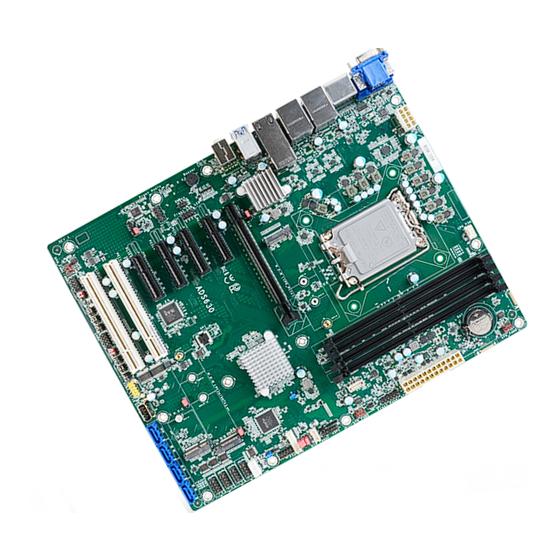
Chapter 2 HARDWARE INSTALLATION Chapter 2 - Hardware Installation X Board Layout Note: Some components are optional and only available upon request. CPU FAN Important: DDR4_1 DDR4_3 Electrostatic discharge (ESD) can damage your board, processor, disk drives, +12V Power add-in boards, and other components. Perform installation procedures at an ESD System HDMI Fan 3... -
Page 11: System Memory
Chapter 2 HARDWARE INSTALLATION X System Memory System Memory Installing the DIMM Module DDR4_1 DDR4_3 +12V Power Battery Before installing the memory module, please make sure that the following safety cautions are Socket LGA1700 well-attended. 1. Make sure the PC and all other peripheral devices connected to it has been powered down. -
Page 12: Removing The Dimm Module
Chapter 2 HARDWARE INSTALLATION System Memory Installing the DIMM Module System Memory Removing the DIMM Module Please follow the steps below to install the memory card into the socket. Please follow the steps below to remove the memory card from the socket. Step 1: Press the eject tabs at both ends of the socket outward and downward to release them from Step 1:... -
Page 13: Cpu
Chapter 2 HARDWARE INSTALLATION X CPU Installing the CPU Fan and Heat Sink The CPU must be kept cool by using a CPU fan with heat sink. Without sufficient air circula- tion across the CPU and heat sink, the CPU will overheat damaging both the CPU and system board. -
Page 14: Jumper Settings
Chapter 2 HARDWARE INSTALLATION X Jumper Settings CLEAR CMOS Data DDR4_1 DDR4_3 +12V Power Battery Socket LGA1700 M2CN4 M.2 M Key PCIe 1 (PCIe x16) DDR4_2 DDR4_4 PCIe 2 (PCIe x4) Intel LAN LED SOJ1 SMBus PCIe 3 (PCIe x4) R680E/Q670E PCIe 4 (PCIe x4) Front Audio... -
Page 15: Dio Power & Voltage - Jp28/29/30
Chapter 2 HARDWARE INSTALLATION Jumper Settings Jumper Settings DIO Power & Voltage - JP28/29/30 AT/ATX Mode - JP26 DDR4_1 DDR4_3 DDR4_1 DDR4_3 +12V Power +12V Power Battery Battery Socket LGA1700 Socket LGA1700 M2CN4 M2CN4 M.2 M Key M.2 M Key PCIe 1 (PCIe x16) PCIe 1 (PCIe x16) DDR4_2... -
Page 16: Ps/2 And Usb Wake Up Select - Jp25
Chapter 2 HARDWARE INSTALLATION Jumper Settings PS/2 and USB Wake up select - JP25 DDR4_1 DDR4_3 +12V Power Battery Socket LGA1700 M2CN4 M.2 M Key PCIe 1 (PCIe x16) DDR4_2 DDR4_4 PCIe 2 (PCIe x4) Intel LAN LED SOJ1 SMBus PCIe 3 (PCIe x4) R680E/Q670E PCIe 4 (PCIe x4) -
Page 17: Connector Power Control - Jp31/32/33
Chapter 2 HARDWARE INSTALLATION Jumper Settings Jumper Settings M.2 Connector Power Control - JP31/32/33 Power Selection for COM1/COM2-TSJP1/TSJP5 DDR4_1 DDR4_3 DDR4_1 DDR4_3 +12V Power +12V Power Battery Battery Socket LGA1700 Socket LGA1700 M2CN4 M2CN4 M.2 M Key M.2 M Key PCIe 1 (PCIe x16) PCIe 1 (PCIe x16) DDR4_2... -
Page 18: Selection For Com1 / Com2 - Tsjp2,3,4 / Tsjp6,7,8
Chapter 2 HARDWARE INSTALLATION Jumper Settings Selection for COM1 / COM2 - TSJP4,3,2 / TSJP8,7,6 TSJP3(COM1), TSJP7(COM2) DDR4_1 DDR4_3 +12V Power Battery Socket LGA1700 „ 1-3, 2-4 On: „ 3-5, 4-6 On: „ 3-5, 4-6 On: RS232 (default) RS422 RS485 M2CN4 M.2 M Key PCIe 1 (PCIe x16) -
Page 19: Rear I/O Ports
Chapter 2 HARDWARE INSTALLATION X Rear I/O Ports The rear panel I/O ports consist of the following: • 2 DP++ • 4 USB 3.2 Gen2 ports • 2.5G LAN 1/2 • 1 HDMI port • 1 VGA port • 10G LAN 1/2 •... -
Page 20: Usb Ports
Chapter 2 HARDWARE INSTALLATION Rear I/O Ports „ USB 2.0 Headers (USB 11/12) USB Ports Assignment Assignment DDR4_3 DDR4_1 +12V Power SBV6 SBV6 Battery Socket LGA1700 USBP_C_11N USBP_C_12N USB 1/2 (USB 3.2 Gen 2) USBP_C_11P USBP_C_12P USB 3/4 (USB 3.2 Gen 2) USB 7/8/9/10 (USB 3.2 Gen 1) N.C. -
Page 21: Graphics Interfaces
Chapter 2 HARDWARE INSTALLATION Rear I/O Ports Graphics Interfaces The display ports consist of the following: • 2 DP++ Port DDR4_3 DDR4_1 +12V Power • 1 HDMI port Battery Socket LGA1700 • 1 VGA port M2CN4 M.2 M Key PCIe 1 (PCIe x16) DDR4_2 DDR4_4 PCIe 2 (PCIe x4) -
Page 22: Lan Ports
Chapter 2 HARDWARE INSTALLATION Rear I/O Ports Rear I/O Ports LAN Ports Audio DDR4_1 DDR4_3 +12V Power Battery Socket LGA1700 DDR4_1 DDR4_3 +12V Power Battery Socket LGA1700 Line-out 2.5G LAN 1/2 M2CN4 M.2 M Key Mic-in PCIe 1 (PCIe x16) DDR4_2 DDR4_4 10G LAN 1/2... -
Page 23: Internal I/O Connectors
Chapter 2 HARDWARE INSTALLATION X Internal I/O Connectors Internal I/O Connectors Digital I/O Connector, DIO Power SATA (Serial ATA) SATA Pin Assignment DDR4_1 DDR4_3 +12V Power DDR4_3 DDR4_1 +12V Power Battery Socket LGA1700 Battery Socket LGA1700 M2CN4 M.2 M Key M2CN4 PCIe 1 (PCIe x16) M.2 M Key... -
Page 24: Com (Serial) Ports
Chapter 2 HARDWARE INSTALLATION Internal I/O Connectors COM (Serial) ports The pin functions of COM1/2 port will vary according to setting. DDR4_1 DDR4_3 +12V Power COM3/4/5/6 : RS232 only Battery Connecting External Serial Ports Socket LGA1700 Your COM port may come mounted on a card-edge bracket. Install the card-edge bracket to an available slot at the rear of the system chassis then insert the serial port cable to the COM connector. -
Page 25: Cooling Fan Connectors
Chapter 2 HARDWARE INSTALLATION Internal I/O Connectors Internal I/O Connectors Cooling Fan Connectors Power Connector CPU FAN1 DDR4_1 DDR4_3 +12V Power „ ATX 8-pin Power Connectors SYS FAN3 Battery Socket LGA1700 +12V 12 24 DDR4_1 DDR4_3 +12V Power +3.3V +12V Battery Socket LGA1700 +12V... -
Page 26: Front Panel
Chapter 2 HARDWARE INSTALLATION Internal I/O Connectors Internal I/O Connectors Front Panel S/PDIF Connector DDR4_1 DDR4_3 +12V Power „ Front Panel Connector Battery Socket LGA1700 DDR4_1 DDR4_3 +12V Power Battery PWR-LED Socket LGA1700 HD-LED M2CN4 M.2 M Key RESET ATX-SW PCIe 1 (PCIe x16) DDR4_2 DDR4_4... -
Page 27: Com1
Chapter 2 HARDWARE INSTALLATION Internal I/O Connectors Internal I/O Connectors COM1 COM2 DDR4_1 DDR4_3 DDR4_1 DDR4_3 +12V Power +12V Power Battery Battery Socket LGA1700 Socket LGA1700 M2CN4 M2CN4 M.2 M Key M.2 M Key PCIe 1 (PCIe x16) PCIe 1 (PCIe x16) DDR4_2 DDR4_4 DDR4_2... -
Page 28: Front Audio
Chapter 2 HARDWARE INSTALLATION Internal I/O Connectors Internal I/O Connectors Front Audio Front LAN LED DDR4_1 DDR4_3 DDR4_1 DDR4_3 +12V Power +12V Power Battery Battery Socket LGA1700 Socket LGA1700 M2CN4 M2CN4 M.2 M Key M.2 M Key PCIe 1 (PCIe x16) PCIe 1 (PCIe x16) DDR4_2 DDR4_4... -
Page 29: Usb 3.2 Gen2 Key B
Chapter 2 HARDWARE INSTALLATION Internal I/O Connectors Internal I/O Connectors USB 3.2 Gen2 Key B PS/2 DDR4_1 DDR4_3 DDR4_1 DDR4_3 +12V Power +12V Power Battery Battery Socket LGA1700 Socket LGA1700 „ USB 3.2 M2CN4 M2CN4 M.2 M Key M.2 M Key PCIe 1 (PCIe x16) PCIe 1 (PCIe x16) DDR4_2... -
Page 30: Usb 2.0
Chapter 2 HARDWARE INSTALLATION Internal I/O Connectors Internal I/O Connectors USB 2.0 USB 2.0 DDR4_1 DDR4_3 DDR4_1 DDR4_3 +12V Power +12V Power Battery Battery Socket LGA1700 Socket LGA1700 M2CN4 M2CN4 M.2 M Key M.2 M Key PCIe 1 (PCIe x16) PCIe 1 (PCIe x16) DDR4_2 DDR4_4... -
Page 31: Expansion Slots
Chapter 2 HARDWARE INSTALLATION Internal I/O Connectors Internal I/O Connectors Expansion Slots Expansion Slots Installing the M.2 Module Before installing the M.2 module into the M.2 socket, please make sure that the following DDR4_1 DDR4_3 +12V Power safety cautions are well-attended. PCIe 1 (PCIe x16) Battery PCIe 2 (PCIe x4) -
Page 32: Battery
Chapter 2 HARDWARE INSTALLATION Internal I/O Connectors Expansion Slots Internal I/O Connectors Battery Please follow the steps below to install the card into the socket. DDR4_1 DDR4_3 +12V Power „ Battery Battery Socket LGA1700 Step 1: Insert the card into the socket at an angle while making sure the notch and key are perfectly aligned. -
Page 33: Chapter 3 - Bios Settings
Chapter 3 Chapter 3 Chapter 3 BIOS SETTINGS BIOS SETTINGS BIOS SETTINGS Chapter 3 - BIOS Settings Legends X Overview The BIOS is a program that takes care of the basic level of communication between the CPU Keys Function and peripherals. It contains codes for various advanced features found in this system board. Right / Left arrow Move the highlight left or right to select a menu The BIOS allows you to configure the system and save the configuration in a battery-backed... -
Page 34: Main
ME FW Version 16.0.15.1531 F9: Optimized Defaults X NVMe Configuration ME Firmware SKU Corporate SKU F10: Save & Exit X DFI WDT Configuration PMC FW Version 160.2.0.7025 ESC: Exit X USB Power Control →←: Select Screen System Date [Mon 01/07/2020] ↑↓: Select Item... -
Page 35: Cpu Configuration
Chapter 3 Chapter 3 Chapter 3 BIOS SETTINGS BIOS SETTINGS BIOS SETTINGS Advanced Advanced CPU Configuration Power & Performance Aptio Setup - AMI Aptio Setup - AMI Advanced Advanced CPU Configuration When enabled, a VMM can Power & Performance CPU - Power Management utilize the additional hard- Control Optionns Intel (VMX) Virtualization... -
Page 36: Pch-Fw Configuration
Chapter 3 Chapter 3 Chapter 3 BIOS SETTINGS BIOS SETTINGS BIOS SETTINGS Advanced Advanced PCH-FW Configuration Aptio Setup - AMI Aptio Setup - AMI Advanced Advanced ME State [Enabled] When Disabled ME will be GT - Power Management Control C h e c k t o e n a b l e r e n d e r Manageability Features State [Enabled] put into ME Temporarily... -
Page 37: Trusted Computing
Chapter 3 Chapter 3 Chapter 3 BIOS SETTINGS BIOS SETTINGS BIOS SETTINGS Advanced Trusted Computing Aptio Setup - AMI Advanced TPM2.0 Device Found Enables or Disables BIOS Firmware Version support for security de - Vendor: v i c e . O . S w i l l n o t s h o w Security Device. -
Page 38: Nct6126D Super Io Configuration
Chapter 3 Chapter 3 Chapter 3 BIOS SETTINGS BIOS SETTINGS BIOS SETTINGS Advanced Advanced NCT6126D Super IO Configuration NCT6126D Super IO Configuration ► Serial Port Configuration Aptio Setup - AMI Aptio Setup Utility - Copyright (C) 2019 American Megatrends, Inc. Advanced Advanced NCT6126D Super IO Configuration... -
Page 39: Nct6126D Hw Monitor
Chapter 3 Chapter 3 BIOS SETTINGS BIOS SETTINGS Advanced NCT6126D HW Monitor NCT6126D HW Monitor Aptio Setup - AMI Advanced Enable CPU SmartFan Pc Health Status ► Smart Fan Function Case Open [Disabled] System temperature : +33 °C CPU temperature : +37 °C SYS_FAN1 : N/A... -
Page 40: Serial Port Console Redirection
Chapter 3 Chapter 3 BIOS SETTINGS BIOS SETTINGS Advanced Advanced Serial Port Console Redirection Serial Port Console Redirection ► Console Redirection Settings Aptio Setup - AMI Aptio Setup - AMI Advanced Advanced Console Redirection En - Enable CPU SmartFan COM1 COM1 able or Disable. -
Page 41: Acpi Configuration
Chapter 3 Chapter 3 Chapter 3 BIOS SETTINGS BIOS SETTINGS BIOS SETTINGS Recorder Mode Advanced With this mode enabled only text will be sent. This is to capture Terminal data. ACPI Configuration Resolution 100x31 Aptio Setup - AMI Advanced Enables or disables extended terminal resolution. RC ACPI Configuration Enable or disable System Putty Keypad... -
Page 42: Usb Configuration
Chapter 3 Chapter 3 Chapter 3 BIOS SETTINGS BIOS SETTINGS BIOS SETTINGS Advanced USB Configuration Aptio Setup - AMI Advanced Enables Legacy USB sup- USB Configuration port. AUTO option disables legacy support if no USB XHCI Hand-off [Enabled] d e v i c e s a r e c o n n e c t e d . USB Mass Storage Driver Support [Enabled] DISABLE option will keep... -
Page 43: Network Stack Configuration
Chapter 3 Chapter 3 Chapter 3 BIOS SETTINGS BIOS SETTINGS BIOS SETTINGS Advanced Advanced Network Stack Configuration DFI WDT Configuration Aptio Setup - AMI Aptio Setup - AMI Advanced Advanced Enable/Disable UEFI Net- Enable/Disable Watchdog Network Stack [Enabled] USB Configuration... -
Page 44: Usb Power Control
Chapter 3 BIOS SETTINGS Advanced Advanced USB Power Control Intel(R) Ehternet Controller X550 Aptio Setup - AMI Aptio Setup - AMI Advanced Advanced Switch USB Power between Firmware Image Properties. USB3_1/2 [5V_Dual] ► Firmware Image Properties 5V_Dual and 5V. USB3_3/4 [5V_Dual] ►... -
Page 45: Chipset
Chapter 3 Chapter 3 Chapter 3 BIOS SETTINGS BIOS SETTINGS BIOS SETTINGS X Chipset Chipset System Agent (SA) Configuration Aptio Setup - AMI Aptio Setup - AMI Main Advanced Chipset Security Boot Save & Exit Main Advanced Chipset Security Boot Save &... - Page 46 Chapter 3 BIOS SETTINGS Chipset Chipset System Agent (SA) Configuration VMD Configuration System Agent (SA) Configuration PCI Express Configuration Aptio Setup - AMI Advanced Aptio Setup - AMI Main Advanced Chipset Security Boot Save & Exit Advanced Chipset PCI Express Configuration E n a b l e o r d i s a b l e V M D VMD Configuration Compliance Test Mode...
-
Page 47: Sata And Rst Configuration
Chapter 3 BIOS SETTINGS Chipset Chipset PCH-IO Configuration SATA Configuration Aptio Setup - AMI Aptio Setup Utility - Copyright (C) 2019 American Megatrends, Inc. Main Advanced Chipset Security Boot Save & Exit Main Advanced Chipset Chipset Security Boot Save & Exit Advanced Chipset Chipset... -
Page 48: Security
Chapter 3 Chapter 3 Chapter 3 BIOS SETTINGS BIOS SETTINGS BIOS SETTINGS X Security Security Secure Boot Aptio Setup - AMI Aptio Setup - AMI Main Advanced Chipset Security Boot Save & Exit Security Password Description S e t A d m i n i s t r a t o r P a s s - System Mode Setup S e c u r e B o o t a c t i v a t e d... -
Page 49: Boot
Chapter 3 Chapter 3 Chapter 3 BIOS SETTINGS BIOS SETTINGS BIOS SETTINGS X Boot X Save & Exit Aptio Setup - AMI Aptio Setup - AMI Main Advanced Chipset Security Boot Save & Exit Main Advanced Chipset Security Boot Save & Exit Boot Configuration The number of seconds Save Options... -
Page 50: Updating The Bios
BIOS with the flash utility. For updating AMI BIOS in UEFI mode, you may refer to the how-to video at https://www.dfi.com/Knowledge/Video/5. X Notice: BIOS SPI ROM 1.
Need help?
Do you have a question about the SU256-SCM-7600U and is the answer not in the manual?
Questions and answers