Table of Contents
Advertisement
Quick Links
Advertisement
Table of Contents

Related Manuals for DFI AD73 Pro


Summary of Contents for DFI AD73 Pro
-
Page 1: System Board
AD73 Pro/B Rev. B1 System Board User’s Manual 935-AD73P2-100 70800308... - Page 2 Copyright Trademarks ® ® ® ® ® ® ® ® ® Caution...
- Page 3 FCC and DOC Statement on Class B...
- Page 4 Notice...
- Page 5 Table of Contents Chapter 1 - Introduction Chapter 2 - Hardware Installation Chapter 3 - Award BIOS Setup Utility...
- Page 6 Introduction Chapter 4 - Supported Softwares Appendix A - Using the Suspend to RAM Function Appendix B - System Error Messages Appendix C - Troubleshooting...
-
Page 7: Features And Specifications
Introduction Chapter 1 - Introduction 1.1 Features and Specifications 1.1.1 Features Chipset ® Processor Important: To ensure proper boot up and operation of your system, you must power-off the system then turn off the power supply’s switch or unplug the AC power cord prior to replacing the CPU. System Memory... - Page 8 Introduction DIMMs DIMMs Memory Size Memory Size 16MB 16MBx64 128MB 2MBx64 32MBx64 4MBx64 32MB 256MB 64MBx64 8MBx64 64MB 512MB Expansion Slots Onboard Audio Features ® Rear Panel I/O Ports (PC 99 color-coded connectors) I/O Connectors...
- Page 9 Introduction PCI Bus Master IDE Controller IrDA Interface USB Ports BIOS ®...
- Page 10 Introduction Desktop Management Interface (DMI) 1.1.2 System Health Monitor Functions 1.1.3 Intelligence CPU Temperature Protection...
- Page 11 Introduction CPU Fan Protection Over Voltage CPU Overclocking Automatic Chassis Fan Off Dual Function Power Button...
- Page 12 Introduction Wake-On-Ring Important: If you are using a modem add-in card, the 5VSB power source of your power supply must support a minimum of ≥ 720mA. RTC Timer to Power-on the System Wake-On-LAN Important: The 5VSB power source of your power supply must support a minimum of ≥...
- Page 13 Introduction ACPI STR ® ® Important: The 5VSB power source of your power supply must support ≥ 1A. Virus Protection...
- Page 14 Introduction 1.2 Package Checklist þ þ þ þ þ...
-
Page 15: Hardware Installation
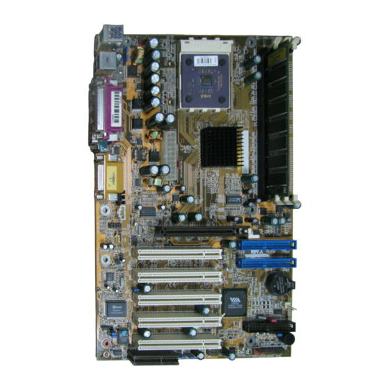
Hardware Installation Chapter 2 - Hardware Installation 2.1 System Board Layout CPU fan (J16) Socket A PS/2 power select (JP3) Power select USB 1 (JP4) DIMM USB 1 standby (J7) power LED COM 1 (J1) Parallel (J8) COM 2 (J2) KT-266A Line (J3) -
Page 16: System Memory
Hardware Installation Warning: • To ensure proper boot up and operation of your system, you must power-off the system then turn off the power supply’s switch or unplug the AC power cord prior to altering the setting of a jumper or replacing the CPU. •... -
Page 17: Installing The Dim Module
Hardware Installation Refer to chapter 1 (System Memor y section) for detailed specification of the memory supported by the system board. 2.2.1 Installing the DIM Module A DIM module simply snaps into a DIMM socket on the system board. Pin 1 of the DIM module must correspond with Pin 1 of the socket. -
Page 18: Jumper Settings For Clearing Cmos Data
Hardware Installation 2.3 Jumper Settings for Clearing CMOS Data 3 2 1 Clear CMOS (JP9) 1-2 On: 2-3 On: Normal (default) Clear CMOS Data Clear CMOS Data - Jumper JP9 If you encounter the following, a) CMOS data becomes corrupted. b) You forgot the supervisor or user password. - Page 19 Hardware Installation 3. Plug the power cord and power-on the system. If your reason for clearing the CMOS data is due to incorrect setting of the processor’s bus clock in the BIOS, please proceed to step 4. 4. After powering-on the system, press <Del> to enter the main menu of the BIOS.
-
Page 20: Jumper Settings For The Onboard Audio Codec
Hardware Installation 2.4 Jumper Settings for the Onboard Audio Codec 3 2 1 Onboard audio codec settings (JP1 & JP2) 1-2 On: 2-3 On: Enable the Onboard Disable the Onboard Audio Codec Audio Codec (default) Onboard Audio Codec Settings - Jumpers JP1 and JP2 The default setting is 1-2 On, the onboard audio codec enabled. - Page 21 Hardware Installation 2.5 Jumper Settings for Selecting the CPU’s Front Side Bus CPU FSB select (JP8) On: 100MHz Off: 133MHz (200MHz FSB) CPU (266MHz FSB) CPU (default) CPU Front Side Bus Select - Jumper JP8 This jumper is used to select the front side bus of the CPU installed on the system board.
-
Page 22: Jumper Settings For Selecting The Usb Power
Hardware Installation 2.6 Jumper Settings for Selecting the USB Power Power select USB 1 (JP4) 3 2 1 Power select USB 2 / 3 (JP7) 2-3 On: 5VSB 1-2 On: 5V (default) Power Select for USB 1 (JP4) and USB 2/USB 3 (JP7) These jumpers are used to select the power for the USB device connected to USB 1 or USB 2/USB 3. - Page 23 Hardware Installation 2.7 Jumper Settings for Selecting the PS/2 Power PS/2 power select (JP3) 2-3 On: 5VSB 1-2 On: 5V (default) Power Select for PS/2 Keyboard/Mouse - Jumper JP3 This jumper is used to select the power for the device connected to the PS/2 keyboard or PS/2 mouse port.
-
Page 24: Ports And Connectors
Hardware Installation 2.8 Ports and Connectors 2.8.1 Serial Ports COM 1 COM 2 (Teal/Turquoise) COM 1 COM 2 Serial Port Serial Port The system board is equipped with onboard serial ports (COM 1: J1 and COM 2: J2) - both in Teal/Turquoise color located at the ATX double deck ports of the board. - Page 25 Hardware Installation 2.8.2 PS/2 Mouse and PS/2 Keyboard Ports PS/2 Mouse PS/2 Keyboard Mouse (Green) (Purple) The system board is equipped with an onboard PS/2 mouse (Green) and PS/2 keyboard (Purple) ports - both at location J6 of the ATX double deck ports of the system board. The PS/2 mouse port uses IRQ12.
- Page 26 Hardware Installation 2.8.3 Parallel Port Parallel (Burgundy) Parallel Port The system board has a standard parallel port (J8 - Burgundy) located at the ATX double deck ports of the board for interfacing your PC to a parallel printer. It supports SPP, ECP and EPP modes. You can set the port’s mode in the Integrated Peripherals submenu (“Super IO Device”...
-
Page 27: Floppy Disk Drive Connector
Hardware Installation 2.8.4 Floppy Disk Drive Connector FDD (J24) The system board is equipped with a shrouded floppy disk drive connector that supports two standard floppy disk drives. To prevent improper floppy cable installation, the shrouded floppy disk header has a keying mechanism. The 34-pin connector on the floppy cable can be placed into the header only if pin 1 of the connector is aligned with pin 1 of the header. -
Page 28: Ide Disk Drive Connectors
Hardware Installation 2.8.5 IDE Disk Drive Connectors Primary IDE (J22) Secondary IDE (J23) The system board is equipped with two shrouded PCI IDE headers that will interface four Enhanced IDE (Integrated Drive Electronics) disk drives. To prevent improper IDE cable installation, each shrouded PCI IDE header has a keying mechanism. - Page 29 Hardware Installation Adding a Second IDE Disk Drive When using two IDE drives, one must be set as the master and the other as the slave. Follow the instructions provided by the drive manufacturer for setting the jumpers and/or switches on the drives. The system board suppor ts Enhanced IDE or ATA-2, ATA/33, ATA/66, ATA/100 and ATA/133 hard drives.
-
Page 30: Universal Serial Bus Ports
Hardware Installation 2.8.6 Universal Serial Bus Ports USB 3 (J28) USB 2 (J27) USB 2 (Black) USB 1 (Black) Onboard USB Ports (J7) Additional USB Ports (J27 & JP28) Function Function UP2- UP3- UP2+ UP3+ Ground Ground Ground... - Page 31 Hardware Installation The system board supports 6 USB ports. USB allows data ex- change between your computer and a wide range of simultane- ously accessible external Plug and Play peripherals. You must have the proper drivers installed in your operating system to use the USB ports.
- Page 32 Hardware Installation 2.8.7 IR and CIR Connector CIR (J12) IR (J11) 5 4 3 2 1 Function N. C. IRRX Ground IRTX The system board is equipped with an IrDA connector for wireless connectivity between your computer and peripheral devices. The IRDA (Infrared Data Association) specification suppor ts data transfers of 115K baud at a distance of 1 meter.
- Page 33 Hardware Installation 2.8.8 CPU Fan Connector with CPU Fan Protection Function CPU fan (J16) Function +12V Sense The CPU must be kept cool by using a CPU fan with heatsink. Without sufficient air circulation across the CPU and heatsink, the CPU will overheat damaging both the CPU and system board.
- Page 34 Hardware Installation with sense pin to support this function. Connect the CPU fan to the 3-pin fan connector at location J16 on the system board. 2. Make sure the “CPU Fan Protection” field in the PC Health Status submenu of the BIOS is set to “Enabled”. Refer to PC Health Status section in chapter 3 for more information.
-
Page 35: Chassis Fan Connector
Hardware Installation 2.8.9 Chassis Fan Connector Chassis fan (J21) Function On/Off +12V Sense If you are installing a chassis fan in the system unit, connect the fan’s connector to J21 on the system board. The fan will provide adequate airflow throughout the chassis to prevent overheating the processor. - Page 36 Hardware Installation 2.8.10 Second Chassis Fan Connector Second chassis fan (J18) Function Ground +12V Ground The second chassis fan connector is used for connecting a fan for the system or a fan for the KT-266A chip. Connect the fan’s connector to J18 on the system board.
- Page 37 Hardware Installation 2.8.11 Game/MIDI Port Game/MIDI Port Game/MIDI (Gold) The Game/MIDI port is identical to that of a standard PC game adapter or game I/O port. Connect an analog joystick to the 15-pin D-sub connector (J12 - Gold) located at the ATX double deck ports of the system board.
-
Page 38: Audio Jacks
Hardware Installation 2.8.12 Audio Jacks Front audio (J9) Mic-in (Pink) Line-out Line-in (Light Blue) (Lime) Onboard Audio Jacks Line-out Line-in Mic-in Front Audio (J9) Function Function Mic+ Ground Mic Power AuD_Vcc (Avcc) AuD_R_Out AuD_R_Return (GND) N. C. AuD_L_Out AuD_L_Return (GND) - Page 39 Hardware Installation Onboard Audio Jacks The system board is equipped with 3 audio jacks. A jack is a one- hole connecting interface for inserting a plug. Line-out Jack (J3 - Lime) This jack is used to connect external speakers for audio output from the system board.
- Page 40 Hardware Installation 2.8.13 Internal Audio (CD-in) Connectors CD-in (J13) CD-in This connector is used to receive Function audio from a CD-ROM drive, TV Left audio channel tuner or MPEG card. Ground Ground Right audio channel...
- Page 41 Hardware Installation 2.8.14 Wake-On-LAN Connector 1 2 3 Wake-On-LAN (J19) Function +5VSB Ground The Wake-On-LAN connector is used to connect to a LAN card that has the same connector. This function will allow the network to remotely power-on a Soft Power Down (Soft-Off) PC. However, if your system is in the Suspend mode, you can power-on the system only through an IRQ or DMA interrupt.
- Page 42 Hardware Installation 2.8.15 Wake-On-Ring Connector Wake-On-Ring (J26) Function Ground The Wake-On-Ring connector is used to connect to an internal modem card that has the same connector. It will allow the system that is in the Suspend mode or Soft Power Off mode to wake-up/ power-on to respond to calls coming through the internal modem card.
- Page 43 Hardware Installation 2.8.16 DIMM and PCI Standby Power LEDs DIMM standby power LED 3.3VSB standby for PCI (JP5) PCI standby power LED DIMM Standby Power LED This LED will turn red when the system’s power is on or when it is in the Suspend state (Power On Suspend or Suspend to RAM).
- Page 44 Hardware Installation Off: On: Default Non-PCI 2.2 spec. 3.3VSB Standby Power to PCI slots - PCI 2.2 spec. Important: Lighted LEDs serve as a reminder that you must power-off the system then turn off the power supply’s switch or unplug the power cord prior to installing any memory modules or add-in cards.
-
Page 45: Power Connector
Hardware Installation 2.8.17 Power Connector ATX power (J17) The pin assignment of the ATX power connector is shown below. Function Function 3.3V 3.3V 3.3V -12V Ground Ground PS-ON Ground Ground Ground Ground Ground PW-OK 5VSB +12V Important: The system board requires a minimum of 300W electric current. -
Page 46: Front Panel Connectors
Hardware Installation 2.8.18 Front Panel Connectors PWR-LED G-LED ATX-SW G-SW Front panel connectors (J25) HD-LED SPEAKER RESET HD-LED: Primary/Secondary IDE LED This LED will light when the hard drive is being accessed. G-LED: Green LED This LED will not light when the system’s power is on or when the system is in the S3 (STR - Suspend To RAM) state. - Page 47 Hardware Installation PWR-LED: Power/Standby LED When the system’s power is on, this LED will light. When the system is in the S1 (POS - Power On Suspend) state, it will blink every second. When the system is in the S3 (STR - Suspend To RAM) state, it will blink every 4 seconds.
-
Page 48: Award Bios Setup Utility
Award BIOS Setup Utility Chapter 3 - Award BIOS Setup Utility 3.1 The Basic Input/Output System The Basic Input/Output System (BIOS) is a program that takes care of the basic level of communication between the processor and peripherals. In addition, the BIOS also contains codes for various advanced features found in this system board. - Page 49 Award BIOS Setup Utility CMOS Setup Utility - Copyright (C) 1984-2001 Award Software Standard CMOS Features Item Help Date (mm:dd:yy) Thu, Feb 14 2003 Time (hh:mm:ss) 4 : 35 : 5 Menu Level IDE Primary Master Press Enter None Change the day, month, IDE Primary Slave Press Enter None year and century...
- Page 50 Award BIOS Setup Utility IDE Primary/Secondary Master/Slave If you wish to define your own drive type manually, select “Manual”. The drive type information should be included in the documentation from your hard disk vendor. If you select ”Auto”, the BIOS will auto-detect the HDD & CD-ROM drive at the POST stage and show the IDE for the HDD &...
- Page 51 Award BIOS Setup Utility Halt On This field determines whether the system will stop if an error is detected during power up. The default setting is All Errors. No Errors The system boot will not stop for any errors detected. All Errors The system boot will stop whenever the BIOS detects a non-fatal error.
-
Page 52: Advanced Bios Features
Award BIOS Setup Utility 3.1.2 Advanced BIOS Features The Advanced BIOS Features allows you to configure your system for basic operation. Some entries are defaults required by the system board, while others, if enabled, will improve the performance of your system or let you set some features according to your preference. - Page 53 Award BIOS Setup Utility operating systems like Windows 95/98/2000/ME/XP or the oper- ® ating system may not install nor work. CPU L1 Cache and CPU L2 Cache These fields speed up the memory access. The default value is enabled. Enable the external cache for better performance. CPU L2 Cache ECC Checking The processors supported by the system board come with built-in Level 2 cache.
- Page 54 Award BIOS Setup Utility Boot Up Floppy Seek When enabled, the BIOS will check whether the floppy disk drive installed is 40 or 80 tracks. Note that the BIOS cannot distinguish between 720K, 1.2M, 1.44M and 2.88M drive types as they are all 80 tracks.
- Page 55 Award BIOS Setup Utility Security Option This field determines when the system will prompt for the pass- word - everytime the system boots or only when you enter the BIOS setup. Set the password in the Set Supervisor/User Pass- word submenu. System The system will not boot and access to Setup will be denied unless the correct password is entered at the prompt.
-
Page 56: Advanced Chipset Features
Award BIOS Setup Utility 3.1.3 Advanced Chipset Features CMOS Setup Utility - Copyright (C) 1984-2001 Award Software Advanced Chipset Features Item Help DRAM Clock/Drive Control Press Enter AGP & P2P Bridge Control Press Enter Menu Level CPU & PCI Bus Control Press Enter System BIOS Cacheable Disabled... - Page 57 Award BIOS Setup Utility DDR DRAM Clock This field is used to select the clock speed of the DDR SDRAM DIMM. By SPD The EEPROM on a DDR SDRAM DIMM has SPD (Serial Presence Detect) data structure that stores information about the module such as the memory type, memory size, memory speed, etc.
- Page 58 Award BIOS Setup Utility DRAM Burst Length The options are 4 and 8. DRAM Queue Depth The options are 2 level, 3 level and 4 level. DRAM Drive Strength The options are Auto and Manual. When this field is set to Manual, you must select a value in the “DRAM Drive Value”...
- Page 59 Award BIOS Setup Utility AGP Master 1 WS Write Set this field to Enabled to add one clock tick to AGP write operations. AGP Master 1 WS Read Set this field to Enabled to add one clock tick to AGP read operations.
-
Page 60: Integrated Peripherals
Award BIOS Setup Utility 3.1.4 Integrated Peripherals CMOS Setup Utility - Copyright (C) 1984-2001 Award Software Integrated Peripherals Item Help USB 2.0 Support Enable VIA OnChip IDE Device Press Enter Menu Level VIA OnChip PCI Device Press Enter Super IO Device Press Enter Init Display First PCI Slot... - Page 61 Award BIOS Setup Utility IDE Primary Master/Slave PIO and IDE Secondary Master/Slave PIO means Programmed Input/Output. Rather than have the BIOS issue a series of commands to effect a transfer to or from the disk drive, PIO allows the BIOS to tell the controller what it wants and then let the controller and the CPU perform the com- plete task by themselves.
- Page 62 Award BIOS Setup Utility Onboard FDC Controller Enabled Enables the onboard floppy disk controller. Disabled Disables the onboard floppy disk controller. Onboard Serial Port 1 and Onboard Serial Port 2 Auto The system will automatically select an I/O address for the onboard serial port 1 and serial port 2. 3F8/IRQ4, 2F8/IRQ3, 3E8/IRQ4, 2E8/IRQ3 Allows you to manually select an I/O address for the onboard...
- Page 63 Award BIOS Setup Utility Onboard Parallel Port 378/IRQ7, 3BC/IRQ7, 278/IRQ5 Selects the I/O address and IRQ for the onboard parallel port. Disabled Disables the onboard parallel port. Parallel Port Mode The options are SPP, EPP, ECP and ECP+EPP. These apply to standard specifications and will depend on the type and speed of your device.
- Page 64 Award BIOS Setup Utility When the system boots, it will first initialize AGP. PCI Slot When the system boots, it will first initialize PCI. OnChip USB Controller This field is used to select the USB ports you want Enabled. USB Keyboard Support By default, USB Keyboard Support is Disabled.
-
Page 65: Power Management Setup
Award BIOS Setup Utility 3.1.5 Power Management Setup The Power Management Setup allows you to configure your system to most effectively save energy. CMOS Setup Utility - Copyright (C) 1984-2001 Award Software Power Management Setup Item Help ACPI Function Enabled ACPI Suspend Type S1(POS) Menu Level... - Page 66 Award BIOS Setup Utility Power Management Option This field allows you to select the type (or degree) of power saving by changing the length of idle time that elapses before the “Suspend Mode” field is activated. Min Saving Minimum power saving time for Suspend mode = 1 Max Saving Maximum power saving time for Suspend mode = 1 min.
- Page 67 Award BIOS Setup Utility MODEM Use IRQ This field is used to set an IRQ channel for the modem installed in your system. Soft-Off by PWRBTN This field allows you to select the method of powering off your system. Delay 4 Sec Regardless of whether the Power Management field is enabled or disabled, if the power button is pushed and released in less than 4 sec, the system enters the Suspend mode.
- Page 68 Award BIOS Setup Utility Wake Up Events Move the cursor to this field and press <Enter>. The following fields will appear. PS2KB Wakeup Select This field allows you to set password or hot key function for the PS/2 keyboard to wake up the system. PS2KB Wakeup from S3/S4/S5 This field allows you to select a suspend mode to enable a PS/2 keyboard to wake up the system.
- Page 69 Award BIOS Setup Utility Resume by Alarm Enabled When Enabled, you can set the date and time you would like the Soft Power Down (Soft-Off) PC to power-on in the “Date (of Month)” and “Resume prior to the date and time set in these fields, the system will give priority to the incoming calls or net- work.
-
Page 70: Reset Configuration Data
Award BIOS Setup Utility 3.1.6 PnP/PCI Configurations This section describes configuring the PCI bus system. It covers some very technical items and it is strongly recommended that only experienced users should make any changes to the default settings. CMOS Setup Utility - Copyright (C) 1984-2001 Award Software PnP/PCI Configurations Item Help Reset Configuration Data... - Page 71 Award BIOS Setup Utility IRQ Resources Move the cursor to this field and press <Enter>. The “IRQ-3” to “IRQ-15” fields will appear. Set each system interrupt to either Legacy ISA or PCI/ISA PnP. PCI/ISA PnP For devices compliant with the PCI bus architecture. Legacy ISA For devices compliant with the original PC AT bus specification.
-
Page 72: Pc Health Status
Award BIOS Setup Utility 3.1.7 PC Health Status CMOS Setup Utility - Copyright (C) 1984-2001 Award Software PC Health Status Item Help CPU Fan Protection Disabled CPU Temp. Prot. Function Disabled Menu Level CPU Temp. Prot. Alarm Current System Temp. 27C/80F Current CPU Temperature 37C/98F... - Page 73 Award BIOS Setup Utility 2. Allow the system to power-off after the 5 warning beeps then check whether the heatsink and fan are mounted properly onto the CPU because high CPU temperature may be due to incorrect fan/ heatsink installation. Now restart the system. If the same problem persist, it may be that the CPU fan is damaged or it is not rotating properly.
- Page 74 Award BIOS Setup Utility 3.1.8 Frequency/Voltage Control CMOS Setup Utility - Copyright (C) 1984-2001 Award Software Frequency/Voltage Control Item Help Auto Detect DIMM/PCI Clk Enabled Spread Spectrum Modulated Disabled Menu Level Clock By Slight Adjust ↑↓→← Move Enter:Select +/-/PU/PD:Value F10:Save ESC:Exit F1:General Help F5:Previous Values...
- Page 75 Award BIOS Setup Utility Method 1: Clear the CMOS data by setting JP9 to 2-3 On. All fields in the BIOS Setup will automatically be set to their default settings. Method 2: Press the <Insert> key and power button simultaneously, then release the power button first.
-
Page 76: Load Optimized Defaults
Award BIOS Setup Utility 3.1.9 Load Fail-Safe Defaults The “Load Fail-Safe Defaults” option loads the troubleshooting default values permanently stored in the ROM chips. These settings are not optimal and turn off all high performance features. You should use these values only if you have hardware problems. Highlight this option in the main menu and press <Enter>. -
Page 77: Set Supervisor Password
Award BIOS Setup Utility 3.1.11 Set Supervisor Password If you want to protect your system and setup from unauthorized entry, set a supervisor’s password with the “System” option selected in the Advanced BIOS Features. If you want to protect access to setup only, but not your system, set a supervisor’s password with the “Setup”... -
Page 78: Exit Without Saving
3.2 Updating the BIOS To update the BIOS, you will need the new BIOS file and a flash utility, AWDFLASH.EXE. You can download them from DFI’s web site or contact technical support or your sales representative. 1. Save the new BIOS file along with the flash utility AWDFLASH.EXE to a floppy disk. - Page 79 Supported Software Chapter 4 - Supported Software 4.1 Desktop Management Interface (DMI) The mainboard comes with a DMI built into the BIOS. DMI, along with the appropriately networked software, is designed to make inventory, maintenance and troubleshooting of computer systems easier. With DMI, a network administrator or MIS engineer can remotely access some information about a particular computer system without physically going to it.
-
Page 80: Using The Dmi Utility
Supported Software 4.1.2 Using the DMI Utility Award DMI Configuration Utility Copyright Award Software Inc, 1996 [Edit DMI] [Add DMI] [Load DMI File] [Save DMI File] BIOS *** BIOS Auto Detect *** System Enclosure/Chassis Type : BIOS Information Processor Handle : 0000 Memory Controller Vendor Name : Memory Module... - Page 81 Supported Software Add DMI 1. Use the ← or → arrow keys to select the Add DMI menu. 2. Highlight the item on the left screen that you would like to add by using the ↑ or ↓ arrow keys, then press <Enter>. 3.
- Page 82 Supported Software 4.2 Drivers, Utilities and Software Applications The CD that came with the system board contains drivers, utilities and software applications required to enhance the performance of the system board. Insert the CD into a CD-ROM drive. The autorun screen (Main Board Utility CD) will appear.
- Page 83 Supported Software 4.2.1 VIA Service Pack ® The VIA Service Pack contains the following drivers. ® • VIA ATAPI Vendor Support Driver • AGP VxD Driver • IRQ Routing Miniport Driver • VIA INF Driver To install VIA Service Pack, please follow the steps below. 1.
- Page 84 Supported Software You must first install VIA Service Pack prior to installing any other ® drivers. However, this may not be the case for some AGP cards. Please read carefully the following information. Important: The VGA driver that came with some AGP cards is already bundled with the AGP VxD driver.
-
Page 85: Audio Drivers
Supported Software 4.2.2 Audio Drivers The audio drivers are supported in the following operating systems: Windows 98, Windows 98 SE, Windows ME, Windows NT and Windows 2000. To install the audio driver, please follow the steps below. 1. - Page 86 Supported Software 4.2.3 USB 2.0 Drivers To install the USB 2.0 driver, please follow the steps below. 1. Click “VIA USB 2.0 Driver”. The following screen will appear. 2. Follow the prompts on the screen to complete installation. 3. Restart the system.
- Page 87 Supported Software 4.2.4 Winbond Hardware Monitor The system board comes with the Hardware Monitor utility con- tained in the provided CD. It is capable of monitoring the system’s hardware conditions such as the temperature of the CPU and sys- tem, voltage, and speed of the CPU and system fans. It also allows you to manually set a range to the items being monitored.
- Page 88 Supported Software 4.2.5 Microsoft DirectX 8.1 To install Microsoft DirectX 8.1, please follow the steps below. 1. Click “Microsoft DirectX 8.1”. The following screen will appear. 2. Click “Yes” to continue. 3. Follow the prompts on the screen to complete installation. 4.
- Page 89 Supported Software 4.2.6 McAfee VirusScan Online The McAfee VirusScan Online is the most reliable and convenient way of protecting your PC from computer viruses. When you install McAfee VirusScan Online, your computer is safe because it automatically scans for viruses and checks for virus updates so that PC protection stays up-to-date.
-
Page 90: Installation Notes
2. All steps or procedures to install software drivers are subject to change without notice as the softwares are occassionally updated. Please go to DFI's web site at "http://www.dfi.com/support1/ download2.asp" for the latest version of the drivers or software applications. - Page 91 Using the Suspend to RAM Function Appendix A - Using the Suspend to RAM Function A.1 Using the Suspend to RAM Function (optional) If you are using the Windows 98 operating system, please follow ® the steps below. Select “Power Management Setup” in the main menu screen and press <Enter>.
- Page 92 Using the Suspend to RAM Function Boot Windows 98. In the Windows 98 desktop, click the ® ® Start button. Move the cursor to Settings, then click Control Panel. To check whether ACPI was properly installed, double-click the System icon. In the System Properties dialog bpx, clicl the “Device Manager”...
- Page 93 Using the Suspend to RAM Function Click File System. In the “Typical role of this computer” field, select “Mobile or docking system”. Click Apply, then click OK. Restart the computer. 10. Repeat step 7 to open the Control Panel dialog box. Double- click the Power Management icon.
- Page 94 Using the Suspend to RAM Function 12. After completing the steps above and you want to power-off the computer, you do not need to go through the process of closing files, applications and operating system. You can power- off the computer at once by pressing the power button or selecting “Standby”...
- Page 95 System Error Message Appendix B - System Error Message When the BIOS encounters an error that requires the user to correct something, either a beep code will sound or a message will be displayed in a box in the middle of the screen and the message, PRESS F1 TO CONTINUE, CTRL-ALT-ESC or DEL TO ENTER SETUP, will be shown in the information box at the bottom.
- Page 96 System Error Message setting than indicated in Setup. Determine which setting is correct, either turn off the system and change the jumper or enter Setup and change the VIDEO selection. FLOPPY DISK(S) fail (80) Unable to reset floppy subsystem. FLOPPY DISK(S) fail (40) Floppy type mismatch.
- Page 97 Troubleshooting Appendix C - Troubleshooting C.1 Troubleshooting Checklist This chapter of the manual is designed to help you with problems that you may encounter with your personal computer. To efficiently troubleshoot your system, treat each problem individually. This is to ensure an accurate diagnosis of the problem in case a problem has multiple causes.
-
Page 98: Troubleshooting
Troubleshooting Monitor/Display If the display screen remains dark after the system is turned on: 1. Make sure that the monitor’s power switch is on. 2. Check that one end of the monitor’s power cord is properly attached to the monitor and the other end is plugged into a working AC outlet. -
Page 99: Floppy Drive
Troubleshooting Floppy Drive The computer cannot access the floppy drive. 1. The floppy diskette may not be formatted. Format the diskette and try again. 2. The diskette may be write-protected. Use a diskette that is not write-protected. 3. You may be writing to the wrong drive. Check the path statement to make sure you are writing to the targeted drive. -
Page 100: Serial Port
Troubleshooting 4. Verify that the attached device works by attaching it to a parallel port that is working and configured correctly. If it works, the printer can be assumed to be in good condition. If the printer remains inoperative, replace the printer cable and try again. Serial Port The serial device (modem, printer) doesn’t output anything or is outputting garbled characters. - Page 101 Troubleshooting 5. If the board fails to function, place the board on a flat surface and seat all socketed components. Gently press each component into the socket. 6. If you made changes to the BIOS settings, re-enter setup and load the BIOS defaults.
Need help?
Do you have a question about the AD73 Pro and is the answer not in the manual?
Questions and answers