Table of Contents

Related Manuals for LEMKEN Zirkon 10 KA


Summary of Contents for LEMKEN Zirkon 10 KA
- Page 1 Operating Instructions Power Harrows Zirkon 10 KA - EN - Item no. 175_3769 3/02.14 LEMKEN GmbH & Co. KG Weseler Straße 5, 46519 Alpen / Germany Telephone +49 28 02 81 0, Fax +49 28 02 81 220 lemken@lemken.com, www.LEMKEN.com...
- Page 3 However, this brief instruction is not a substitute for thorough study of the operating instructions. These operating instructions will help to familiarise you with the LEMKEN GmbH & Co. KG device and the options available for using it.
- Page 4 Remember that you should only use genuine LEMKEN spare parts. Reproduction parts have a negative influence on the function of the device, have a shorter ser- vice life and present risks and hazards that cannot be estimated by LEMKEN GmbH & Co. KG. They also increase the maintenance costs.
-
Page 5: Table Of Contents
Contents CONTENTS Contents ........................... 3 General information ....................10 Liability ......................... 10 Guarantee ........................10 Copyright ........................11 Optional accessories ....................11 Symbols used in the Operating Instructions ............12 ... - Page 6 Contents Operation on public highways ................... 23 3.9.1 Lighting system and identification ................23 3.9.2 Requirements of the tractor ..................23 3.9.3 Permissible transport speed ..................24 3.9.4 Check before departure ..................... 24 ...
- Page 7 Contents Working depth ......................37 Rear levelling bar ......................37 Track loosener ......................38 Scraper ......................... 38 Preparations on the tractor ..................39 Swinging drawbar ....................... 39 Required hydraulic equipment ...................
- Page 8 Contents Adjustments ......................62 11.1 Tilt ..........................63 11.1.1 Mechanical ......................63 11.1.2 Hydraulic ........................ 63 11.2 Working depth ......................64 11.3 Knife tines with quick-coupling system ..............65 ...
- Page 9 Contents 12.3 Clearance between scraper and roller casing ............83 12.4 Tilt of the roller ......................84 12.4.1 Trapeze rollers TPW and TSW ................84 12.4.2 Toothed packer rollers ZPW ................... 85 Hydraulic three-point Linkage ................
- Page 10 Contents 16.4.2 Electrical connections ..................... 95 16.5 Oil changing ......................... 96 16.5.1 Lubricants for the manual gearbox and lateral right angle drives ......97 16.6 Gear trough ........................98 16.7 Fans ..........................99 ...
- Page 11 Contents Type plate ....................... 113 Noise, Airborne Sound ..................114 Notes ........................114 Index ..........................115 EU Declaration of Conformity ..................117 ...
-
Page 12: General Information
Co. KG, in particular Section IX, shall apply. Liability. In line with the dimensions cited in these conditions the LEMKEN GmbH & Co. KG shall not be held liable for any personal or material damage, when such damage is caused by one or more of the following reasons: ... -
Page 13: Copyright
Infringements will result in a claim for damages. Optional accessories LEMKEN implements may be equipped with various accessories. The operating instructions below describe both series components and optional accessories. Please note: These accessories will vary depending on the type of equipment. -
Page 14: Symbols Used In The Operating Instructions
Symbols used in the Operating Instructions SYMBOLS USED IN THE OPERATING INSTRUCTIONS Hazard classes The following symbols are used in the Operating Instructions for particularly im- portant information: DANGER Denotes an imminent hazard with high risk, which will result in death or severe physical injury, if not avoided. -
Page 15: Indication Of Passages
Symbols used in the Operating Instructions Indication of passages The following symbols are used for particular passages in the operating instruc- tions: Indicates work steps Indicates enumerations... -
Page 16: Safety Measures And Precautions
Safety measures and precautions SAFETY MEASURES AND PRECAUTIONS General safety instructions for the operator are specified in the chapter entitled «Safety measures and precautions». At the start of some main chapters the safety instructions, which refer to all work to be carried out in this chapter, are listed to- gether. -
Page 17: Safety Features Of The Device
Safety measures and precautions Safety features of the device To protect the operator and the device, the device is equipped with special safety features in accordance with country specific requirements. Always keep all safety devices in working order. Safety and warning signs 3.4.1 General information The implement features all equipment which ensures safe operation. - Page 18 Safety measures and precautions Before carrying out maintenance or repair work, switch off the engine and remove key. Do not remain in the operating and swivel area of the implement. Danger of crushing. Danger through moving machine parts. The power takeoff shaft drive-through runs to the right.
- Page 19 Safety measures and precautions Keep out of the folding area of the device. Do not touch any moving machine parts. Wait until they have come to a standstill. Hot surfaces Lock the lifting device Lock the lifting device before travelling on public roads.
-
Page 20: Meaning Of Other Symbols
Safety measures and precautions 3.4.3 Meaning of other symbols. Load-securing points 3.4.4 Position of safety and warning stickers... -
Page 21: Special Safety Instructions
Safety measures and precautions Special safety instructions Risk of injury due to non-observance of the currently valid occupational safety guidelines If the currently valid occupational safety guidelines are bypassed WARNING or safety equipment is rendered unusable when handling the de- vice, there is a risk of injury. -
Page 22: Danger Areas
Safety measures and precautions Risk of injury when freeing casualties When rescuing people trapped or injured by the device, there is a risk of additional serious injury to the casualty if the hydraulic con- nections were not connected according to their colour coding as described in the section entitled "Required hydraulic equipment". -
Page 23: Danger Areas When Operating The Implement
Safety measures and precautions 3.6.1 Danger areas when operating the implement 3.6.2 Danger area when folding in and out... -
Page 24: Residual Risks
Safety measures and precautions Residual risks Residual risks are particular hazards which occur when handling the device and which cannot be eliminated despite a design in accordance with safety require- ments. Residual risks are not usually obvious and may be the source of a potential injury or health hazard. -
Page 25: Operation On Public Highways
Safety measures and precautions Operation on public highways 3.9.1 Lighting system and identification A proper lighting system, identification and equipment must be on the device if it is to be transported on public roads. Further information can be requested from the appropriate authorities. -
Page 26: Permissible Transport Speed
Safety measures and precautions 3.9.3 Permissible transport speed The permissible transport speeds depending on tyres and implement equipment can be found in the table below. Any applicable national road traffic legislation must also be observed. Equipment Max. permissible transport speed 50 km/h 40 km/h 30 km/h... -
Page 27: Correct Behaviour In Road Traffic
Safety measures and precautions 3.9.5 Correct behaviour in road traffic When driving on public highways, observe the relevant statutory national regu- lations. Driving behaviour, steering and braking performance are influenced by ballast weights. Ensure that the tractor has adequate steering and braking performance. ... -
Page 28: Operating The Device Safely
Safety measures and precautions Operate the device only in compliance with all connection and default values provided by the manufacturer! Use original spare parts only! 3.11 Operating the device safely 3.11.1 General information Before starting work, familiarise yourself with all equipment and actuating ele- ments as well as their functions. -
Page 29: Personnel Selection And Qualifications
Safety measures and precautions In the wider operating range of the device there is a risk of injury, e.g. from ejected stones. Before actuating hydraulic equipment (such as flap devices), ensure that there is nobody in the flap area. Risk crushing and/or shearing by remote power op- erated parts. -
Page 30: Power Take-Off Operation
Safety measures and precautions Check hydraulic hose lines regularly and replace if damaged or showing signs of aging. The replacement hose lines must meet the technical requirements stipulated by the implement manufacturer. When searching for leaks, use appropriate equipment because of the risk of in- jury. - Page 31 Safety measures and precautions When working with the power take-off, no one should ever be standing in the vicinity of the rotating power take-off or cardan shaft. The power take-off should always be switched off if the angular deflections are too great and it is not required.
-
Page 32: Handing Over The Device
Handing over the device HANDING OVER THE DEVICE As soon as the device is delivered, ensure that it corresponds with the order package. Also check the type and completeness of any supplied accessories. When the device is handed over, your dealer will explain how it works. ... -
Page 33: Layout And Description
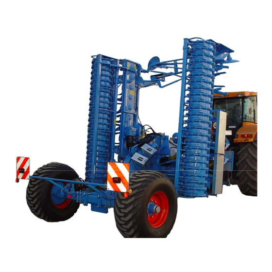
Layout and description LAYOUT AND DESCRIPTION Overview Drawbar with traction loop Gearbox Tines Side shields Rear PTO Rollers Levelling bar Manual gearbox Angular gearbox 10. Feed disc 11. Track marker... -
Page 34: Description
Layout and description 12. Wheelmark eradicator 13. Lighting equipment (not shown) 14. Three-point linkage, hydraulic (not shown) 15. Safety guard 16. Braking system (not shown) Description 5.2.1 Drawbar with coupling The drawbar can be equipped with a 50 mm, 58 mm or 40 mm coupling for at- tachment to a double-axle swinging drawbar or can be equipped with a K80 ball coupling. -
Page 35: Side Blades
Layout and description 5.2.4 Side blades The height-adjustable side blades (1) and the extensions (2) prevent the outer tines from building up ridges. 5.2.5 Power takeoff shaft drive-through The rotational speed and direction of rotation for the power takeoff shaft drive- though corresponds to the rotational speed and direction of rotation for the tractor power takeoff shaft. -
Page 36: Gearbox
Layout and description 5.2.8 Gearbox The manual gearbox shifts the speed by means of the shifting lever. Depending on the shifting position, the speed can be set to 330 or 440 revolutions of the rotor per minute with a 1000-rpm power take-off. The direction of rotation of the rotors can be changed by moving the right angle drives to the side. -
Page 37: Three Point Linkage, Hydraulic
Layout and description 5.2.13 Three point linkage, hydraulic A hydraulic three-point linkage (1) is avail- able for use in combination with a seed drill. The three-point linkage (1) conforms to category 2 and is single-acting or double- acting, depending seed drill manufacturer. -
Page 38: Without Brake System
Layout and description 5.2.16 Without brake system For implements without brake systems, running axles or brake axles without actua- tion devices are used. Safety chain According to national regulations, a safety chain (1) may be required for implements without a brake system. The safety chain is only intended as a safety component. -
Page 39: Using The Implement For The First Time
Using the implement for the first time USING THE IMPLEMENT FOR THE FIRST TIME CAUTION Gloves must be worn for all adjustment work. Before each use, check that all safety equipment is working properly and use or operate it in accordance with these operating instructions. The following settings must be made so that the implement can be used to its op- timum effect. -
Page 40: Track Loosener
Using the implement for the first time Track loosener The height of the track loosener (4) must be set low enough so that it is approx. 5 cm below the surface of the wheel track. In all cases it must be somewhat lower than the tines. -
Page 41: Preparations On The Tractor
Preparations on the tractor PREPARATIONS ON THE TRACTOR Swinging drawbar The tractor must be equipped with a dou- ble axle swinging drawbar (1) which is de- signed for a vertical load of at least 2,000 Pull out the swinging drawbar until di- mension A and B are equal. -
Page 42: Required Hydraulic Equipment
Preparations on the tractor The smallest turning radius is determined by the length (L) of the telescoped drive shaft (5). The minimum overlap is 240 mm in the straight position. Required hydraulic equipment The implement is supplied with separate hydraulic connections for each consum- er. -
Page 43: Mounted Implement With Separate Hydraulic Connections
Preparations on the tractor 7.2.1 Mounted implement with separate hydraulic connections Tractor / Implement Consumer single-acting double-acting Colour Code Folding mechanism Chassis, mounting device green Track markers black Three-point hydraulic Blue linkage 7.2.2 Mounted implement with 6/2-way valve Tractor / Imple- Connection bra- double- ment... -
Page 44: Mounted Implements With Electromagnetic Control
Preparations on the tractor 7.2.3 Mounted implements with electromagnetic control Tractor / Implement Connection bra- double- cket single-acting Consumer acting Colour Code Colour Code Forward Forward = With pres- = yellow yellow, Hydraulic motor for blo- sureless re- Return = Return turn connec- white... -
Page 45: Mounted Implements With Electronic Control
Preparations on the tractor 7.2.4 Mounted implements with electronic control Tractor / Implement Connection bra- double- cket single-acting Consumer acting Colour Code Colour Code Forward Forward = With pres- = yellow yellow, Hydraulic motor for blo- sureless re- Return = Return turn connec- white... -
Page 46: Mounted Implements With Hydraulic Equipment For Stand-Alone Operation
Preparations on the tractor 7.2.5 Mounted implements with hydraulic equipment for stand-alone opera- tion If an implement is used in stand-alone-mode, the hoses of the hydraulic equip- ment must be connected to separate tractor control units. Tractor / Implement double- single-acting Consumer acting... -
Page 47: Acoustic Drive Shaft Monitoring
Preparations on the tractor The following power sources are required on the tractor for the electrical consum- ers: Consumers Volts Direct connection to Power socket the tractor battery Lighting system In accordance with DIN-ISO 1724 Cardan shaft monitor In accordance with DIN 9680 7.3.1 Acoustic drive shaft monitoring A power socket compliant with DIN 9680 is required for the supply to the drive... -
Page 48: Preparations On Implement
Preparations on implement PREPARATIONS ON IMPLEMENT Final assembly For transportation-specific reasons, the implement is not always delivered in a ful- ly-assembled condition. Use the implement only when the implement has been fully assembled and a functional check has been performed. Drawbar coupling The gear unit sumps of the rotary harrow must be horizontal relative to the ground... -
Page 49: Coupling And Uncoupling Implement
Coupling and uncoupling implement COUPLING AND UNCOUPLING IMPLEMENT Risk of injury when coupling the device WARNING There is a risk of body parts being crushed between the tractor and device The tractor must be secured against unintentionally rolling away. Never actuate the hydraulic system of the tractor if there are people between the tractor and device. -
Page 50: Attaching
Coupling and uncoupling implement Attaching Drive the tractor up to the implement. Connect the hydraulic hoses according to corresponding attachment points of the tractor according to the section "Re- quired hydraulic equipment", page 40. Adjust the height of the drawbar coupling (1) via the hydraulic cylinder (2) until it is at the same height as the double axle swinging drawbar. - Page 51 Coupling and uncoupling implement Remove the drive shaft (7) from the holder. Connect the drive shaft (7) to the PTO shaft of the tractor. Swivel the drive shaft mount (7) up- wards. Secure the mount with the folding plug. ...
- Page 52 Coupling and uncoupling implement Fully raise the implement with the hy- draulic cylinder (10). Fully fold in the implement. To do this, the hydraulic folding device must be ac- tivated and the shut-off valves (7) opened by pulling the activation cables (6).
- Page 53 Coupling and uncoupling implement Release the parking brake by pressing the red button (16). Depending on national regulations, attach the safety chain to the tractor. Always comply with any applicable national regulations. The safety chain must be attached such that: ...
- Page 54 Coupling and uncoupling implement Push the pin (1) inwards. Push the lock (2) away from the hook (3). The lock may also be placed cross- wise. Attach the safety chain (4) to a sufficient- ly robust attachment point on the tractor. ...
-
Page 55: Detaching
Coupling and uncoupling implement Detaching The implement can be parked both when it is folded in or folded out. If the implement is to be parked when it is folded in, the parking supports (1) must be attached. Pull the parking supports (1) out in a downward direction. - Page 56 Coupling and uncoupling implement Open the shut-off valve (11) by pushing the handle extension (12) backwards. Lower the implement with the hydraulic cylinder (10) until the load on the draw- bar coupling is relieved and is not in con- tact with the swinging drawbars.
- Page 57 Coupling and uncoupling implement Swivel the mount (17) of the drive shaft (7) downwards. Remove the drive shaft (7) at the tractor end. Lay the drive shaft (7) in the holder. Remove the wedges (13) from the hold- er (14).
- Page 58 Coupling and uncoupling implement In a hydraulic braking system, you acti- vate the parking brake by pulling the lever (17). Depending on the model and national regulations: Release the safety chain (4). To do this, push the pin (5) on the safety chain inwards.
-
Page 59: Operation
Operation OPERATION 10.1 Turning at the headland DANGER Risk of damage to components If the implement is not fully raised, there is a danger that compo- nents may be damaged during an improper turn at the headland. Before turning at the headland the implement must be completely raised before turning-in to avoid any damage to the implement. -
Page 60: Drive Shaft Monitoring
Operation 10.3 Drive shaft monitoring Drive shaft monitoring can be carried out both electronically in combination with the Solitair seed drill machine via the Solitronic seed drill control unit Version 1.17 and above, or acoustically via the warning box (1). Monitoring of the drive shaft via the electronic version is not pos- sible with stand-alone operation of the implement. -
Page 61: Retracting/Extending
Operation Monitoring is carried out via the speed sensors (3) and the control terminal of the Solitronic electronic seed drill machine control unit or the warning box (1), which is supplied with power from a distributor box. The warning box (1) is installed in the trac- tor cab, like the control terminal. - Page 62 Operation Raise the implement all the way. Retract the side sections to the end posi- tion by moving the tractor's control unit to the "Retract position" = 1st pressure position. Pull the traction cables (1) at the same time.
-
Page 63: Extending
Operation 10.4.2 Extending The implement must only be extended when parked. Before extending the implement on the field, the rear lighting system with warning signs must be removed. Pull the traction cables (1) of the hydrau- lic extension lock to open the valves (2). ... -
Page 64: Adjustments
Adjustments ADJUSTMENTS Risk of accident when making adjustments When making any adjustments to the device, there are risks of crushing, cutting, clamping and striking your hands, feet and body on heavy and occasionally compressed and/or sharp-edged parts. Always park implement on the ground. DANGER ... -
Page 65: Tilt
Adjustments 11.1 Tilt 11.1.1 Mechanical Adjust the position of the rotary harrow with the upper link (1) so that the PTO shaft of the PTO through drive (2) and the input shaft of the middle gear unit (3) are as parallel as possible in the working position. -
Page 66: Working Depth
Adjustments 11.2 Working depth The power harrow's working depth is geared towards the required working effect. Generally, the power harrow should be operated as flat as possible. Raise the power harrow. Pull the spring pin (2) out. Move the adjusting rod to set the work- ing depth (3). -
Page 67: Knife Tines With Quick-Coupling System
Adjustments 11.3 Knife tines with quick-coupling system When the bar (2) is unlocked, it is easy to change the tines (1) manually as fol- lows; CAUTION The safety stirrup is under enormous spring tension. It may only be lifted back with a suitable tool such as a screwdriver. ... -
Page 68: Manual Gearbox
Adjustments New knife tines with quick-coupling system are mounted in the reverse order to the order described above. They are inserted into the tine carrier (4) and then pushed inwards. Secure tines with the bar (2). The bar (2) is locked by lifting back the safety stirrup (3). - Page 69 Adjustments Before the gear shift: the tractor's power takeoff shaft has to be switched off. the gearbox has to be cold. Shifting lever (2) in front locking position = rotor speed 440 rpm with 1000 rpm power takeoff shaft speed. Shifting lever (2) in rear locking position = rotor speed 330 rpm with 1000 rpm power takeoff shaft speed.
-
Page 70: Rotor Speeds
Adjustments 11.4.2 Rotor speeds The following rotor speeds are available, depending on PTO speed: Option 1 Option 2 If the overload clutch on the cardan shaft is activated too frequent- ly in non-stony soils at a PTO speed of 540 rpm or 750 rpm, a PTO speed of 1000 rpm should be selected with the appropriate gear. - Page 71 Adjustments Recommended working speed depending on rotor speed Rotor speed per minute The rotor speed can be changed using the shifting lever. The 1000 rpm power take-off speed should always be selected. If a power take-off speed of 540 rpm or 750 rpm is used, then the input torque increases by 85 % or by 33 % and it does so at the same power transfer.
-
Page 72: Change In The Direction Of Rotation Of The Rotors
Adjustments 11.5 Change in the direction of rotation of the rotors The direction of rotation may only be changed when the tractor power take-off is switched off and the tractor engine is at a standstill. The direction of rotation of the rotors with quick-change tines can be changed by moving the gearbox (1) to the side. -
Page 73: Power Takeoff Shaft Drive-Through
Adjustments First, screw in all of the centring nuts (4) a little. Then tighten the centring nuts (4) with a tightening torque of 240 Nm. If the centring nuts (4) are not properly tightened, the tractor pow- er take-off must not be switched on. ... -
Page 74: Side Blade
Adjustments 11.7 Side blade Move the side blade into the working position before working with it. The height of the spring-mounted side blades (2) is to be adjusted such that they cover the rotating tools completely. When worn they must be lowered accordingly. Once they have been lowered, tighten the bolts (3) again. -
Page 75: Relocation At The Side
Adjustments 11.9.1 Relocation at the side Adjust the wheelmark eradicator (1) to the bout of the tractor as follows: Raise the implement to relieve the load- ing on the wheelmark eradicator (1). Undo the screw (3) in the holder (4). ... -
Page 76: Feed Discs
Adjustments 11.10 Feed discs The feed discs (1) prevent damming, facilitating precision during the next run. Mount the feed disc (1) console (2) on the outside of the bracket (3). 11.10.1 Relocation at the side On the bracket (3), move the feed disc (1) to the required working width. -
Page 77: Protective Equipment
Adjustments 11.11 Protective equipment To ensure safe operation, the protective equipment must always remain on the implement. with levelling beam (1) and roller (2) without levelling beam Mount the additional protective tube (3). -
Page 78: Stop Screws
Adjustments 11.12 Stop screws Use the stop screws (1) to adjust the base frame and the retracted implement so that the side sections are vertical when in transport position and do not bump against the seed drill when it is attached. In this way the maximum permitted transport width of 300 cm will not be exceed- ... -
Page 79: Levelling Beam
Adjustments 11.13 Levelling beam CAUTION Before adjusting the levelling beam, always move the side blade into the working position. The circular spike harrow can be equipped at the rear or front with a levelling beam (1). 11.13.1 Rear-mounted levelling beam Set the levelling beam (1) using the rough- turning gauge (2) so that the lower edge of the levelling beam is about 2 cm over the... -
Page 80: Track Markers
Adjustments 11.14 Track markers CAUTION Before operating the track markers, always make sure that no persons are present in the danger zone. To ensure the implement runs more pre- cisely track-to-track, especially in combina- tion with a seed drill, track markers are available that can be bolted onto the carri- ers (2). - Page 81 Adjustments The adjusting dimensions are available in the following table. The dimensions refer to a marking groove in the centre of the tractor track. Distance from middle of Distance from outer seeding Zirkon 10 K / 10 KA seed drill to the track groove coulter 400 cm 200 cm + ½...
-
Page 82: Shearing Protection
Adjustments 11.14.2 Shearing protection A shear bolt (1) protects the track markers against overloading. If a shear bolt has broken: Remove the remains of the bolt. Fit a new shear bolt (1). Tighten shear bolt (1). «Tightening torques, page 103». Shear bolt Implement Size... -
Page 83: Rollers
Rollers ROLLERS 12.1 General information The machine can be equipped with a variety of rollers: tube bar roller RSW 540, trapezoidal packing roller TPW 500, trapezoidal disk roller TSW 500, Rubber ring roller GRW 590 toothed packer rollers ZPW 500. The tube bar and trapezoidal ring rollers are maintenance-free. -
Page 84: Adjusting The Scrapers
Rollers 12.2 Adjusting the scrapers The adjustable scrapers (1) for the size 500 rollers are adjusted using setting nuts (2) or eccentric nuts (3). Adjust the setting nuts (2) for the toothed packer rollers using a 19 mm wrench and the eccentric nuts (3) using a 24 mm wrench. -
Page 85: Clearance Between Scraper And Roller Casing
Rollers 12.3 Clearance between scraper and roller casing The clearance between the scraper (1) and the roller casing (5) must be set in line with the following schedule. The adjusting instructions apply to all toothed packer rollers, trapezoidal packer rollers and trapezoidal disk rollers. Heat-treated scraper (1) Plastic scraper (1) (must make contact with roller casing (5) -
Page 86: Tilt Of The Roller
Rollers 12.4 Tilt of the roller If necessary the tilt of the roller can be adjusted as follows: 12.4.1 Trapeze rollers TPW and TSW Loosen the bolt (1) so that it can be moved in the slot. Pull the roller back in the slot. ... -
Page 87: Toothed Packer Rollers Zpw
Rollers 12.4.2 Toothed packer rollers ZPW Loosen the bolt (1) so that it can be moved in the slot. Pull the roller back in the slot. Remove the bolt (2) from bore (5) and place it in bore (6). ... -
Page 88: Hydraulic Three-Point Linkage
Hydraulic three-point Linkage HYDRAULIC THREE-POINT LINKAGE 13.1 Mounting an implement The soil cultivation implement with com- bined semi-mounted equipment is availa- ble with hydraulic three-point linkage (1) of category II for mounting an implement, e.g. a seed drill with own chassis. The mounted implement is connected to the lower link unit (2) of the three-point linkage via a rail shaft and secured by... -
Page 89: Dismounting The Implement
Hydraulic three-point Linkage 13.3 Dismounting the implement Prepare implement in such a way that it can be parked safely. Lower implement and uncouple all supply lines. Uncouple top link (4) on the im- plement side and lay in the holder. Unlock and dismount locking bar (3). Lower three-point linkage and drive soil cultivation implement carefully away from the implement. -
Page 90: Semi-Mounted Devices
Semi-mounted devices SEMI-MOUNTED DEVICES 14.1 Tyres The semi-mounted devices are available with the tyres mentionned in the follow- ing table. Depending on the tyre size, the profile and the PR number the following minimum and maximum air pressures are permissible. In case of large working widths and in conjunction with mounted or semi-mounted implements (combined semi- mounted devices) the higher air pressure values should be selected. -
Page 91: Switching Off The Device
Switching off the device SWITCHING OFF THE DEVICE 15.1 Shutting down the device in an emergency In an emergency shut down the device via the tractor. Switch the tractor engine off. Remove the ignition key. Damage caused by improper storage of the device If incorrectly or improperly stored, the device may be damaged, CAUTION e.g. -
Page 92: Maintenance And Repairs
Maintenance and repairs MAINTENANCE AND REPAIRS 16.1 Special safety instructions 16.1.1 General Risk of injury when carrying out maintenance and repair work There is always the risk of injury when carrying out maintenance and repair work. WARNING Use suitable tools, suitable climbing aids, platforms and support elements. -
Page 93: Immobilise The Implement For Maintenance And Repairs
Maintenance and repairs 16.1.4 Immobilise the implement for maintenance and repairs Risk of accidents when tractor starts up Injuries may occur if the tractor starts moving during maintenance and repair work. Switch off the tractor engine before carrying out any work on the WARNING implement. -
Page 94: Working Under The Raised Device
Maintenance and repairs 16.1.7 Working under the raised device Risk of accident due to lowering and extending of compo- nents and devices It is extremely dangerous to work under raised or next to retracted WARNING components and devices. Always secure the tractor to prevent it from rolling away. Re- move the ignition key and secure the tractor to prevent it from being started up by unauthorised persons. -
Page 95: Environmental Protection
Maintenance and repairs Risk of accident due to tool slipping off If applying a large force, e.g. when loosening bolts, the tool may WARNING slip off. This may result in hand injuries on sharp-edged parts. Avoid applying a large force by using suitable auxiliary equip- ment (e.g. -
Page 96: Maintenance Intervals
Replace damaged or defective hydraulic hoses im- mediately. The hydraulic hoses must be replaced 6 years after the date of manufacture at the latest. Only used hydraulic hoses approved by Lemken. Check that all safety equipment is functioning Safety equipment properly. -
Page 97: Check The Connections To The Tractor
Maintenance and repairs 16.4 Check the connections to the tractor 16.4.1 Hydraulic connections Risk of accidents due to escaping hydraulic fluid Hydraulic fluid which is ejected under high pressure (hydraulic oil) WARNING can penetrate the skin and cause serious injuries. In the event of injuries, consult a doctor immediately. -
Page 98: Oil Changing
Maintenance and repairs 16.5 Oil changing Before changing oil or checking the oil lev- el, the implement must be extended and parked on level and horizontal ground. Check the gearbox's oil level daily. The oil must always reach up to the check screw (3) for each gearbox. -
Page 99: Lubricants For The Manual Gearbox And Lateral Right Angle Drives
Maintenance and repairs 16.5.1 Lubricants for the manual gearbox and lateral right angle drives Only the following lubricants may be used for the implement: Manual gearbox Lateral right angle drives 7.5 l synthetic oil 1.8 l mineral oil Mobil SHC 632 Mobilube HD 85W-140 (Mobil) BP Energear FE SAE 80W-140 (BP) Deagear EP-C SAE 85W-140 (DEA) -
Page 100: Gear Trough
Maintenance and repairs 16.6 Gear trough CAUTION Before checking the oil level and free-flowing grease level: Switch off the power take-off and tractor engine. Remove the ignition key. The free-flowing grease in the gear trough is a long-life grease; it does not have to be changed until 4000 operating hours have elapsed. -
Page 101: Fans
Maintenance and repairs When changing the free-flowing grease, make sure that work is car- ried out cleanly. Dispose of drained free-flowing grease in a proper manner. Do not mix the free-flowing grease with any other grease. 16.7 Fans The centre gearbox (1) is equipped with two fans (2) starting at a working width of 5... -
Page 102: Lubrication
Maintenance and repairs 16.8 Lubrication The lubrication points must be greased with a universal grease according to the maintenance schedule. Lubrication chart every every every every Before the After the winter winter break break ope- ope- ope- opera- rating rating rating ting hours... - Page 103 Maintenance and repairs...
-
Page 104: Rotor Bearings
Maintenance and repairs 16.9 Rotor bearings The bearings of the rotors must be checked regularly fore play to prevent damage of the gears and the transmission pan. Check the bearings of the rotors up to 1000 operating hours every 200 operating hours ... -
Page 105: Bolts
Maintenance and repairs 16.10 Bolts After the first few hours of use - but after eight hours of use at latest - all nuts and bolts must be tightened. After this, nuts and bolts must be checked after every 50 hours of operation to check that they are secure. -
Page 106: Bolts And Nuts Made Of Steel
Maintenance and repairs 16.11.2 Bolts and nuts made of steel Strength category Diameter 10.9 12.9 [Nm*] [Nm*] [Nm*] 13,6 16,3 23,4 32,9 39,6 M 10 46,2 64,8 77,8 M 12 80,0 M 14 M 16 M 20 M 24 1112 M 30 1314 1850... -
Page 107: Tines
Maintenance and repairs 16.12 Tines Worn tines are to be replaced in good time. Risk of accident when implement lowered Performing work under raised components/implements or next to WARNING swivelled-in components/implements is life-threatening. Always secure the tractor against rolling away, remove the igni- tion key and and secure the tractor against any unauthorised start-up. -
Page 108: Hydraulic Hoses
Porouse or defective hydraulic hoses must be changed immediately. Use hydraulic hoses only, which are accepted by Lemken! Important: Do not clean this implement with a Pressure Washer during the first 6 weeks. After this time a minimum nozzle distance of 60 cm must be... -
Page 109: Troubleshooting
Troubleshooting TROUBLESHOOTING Before carrying out troubleshooting, it is essential to ensure that CAUTION the implement is parked on the ground the power take-off and tractor engine are switched off the ignition key is removed. Only then can the fault be repaired. 17.1.1 General information Fault Cause... -
Page 110: Information For Driving On Public Roads
TÜV or DEKRA and after presentation of the certificate to the responsible Road Traffic Licensing Department. The type report which is required for the presentation is supplied with each im- plement or can be requested from Lemken. 18.2 Braking deceleration It must be ensured that the tractor and implement (braked or unbraked) always meets the specified braking deceleration. -
Page 111: Safety Devices
Information for driving on public roads Pull the handle extension (4) forwards to close the shut-off valve (3). This prevents the power harrow from sink- ing accidentally. 18.4 Safety devices The safety devices (1) must be attached when driving on public roads. ... -
Page 112: Feed Discs
Information for driving on public roads 18.5 Feed discs If feed discs are fitted: Fold in the side panels. Lock the side panels. Unlock the feed discs. Remove the feed discs from the holder. Insert the feed discs into the holder from above. ... -
Page 113: Allowed Transport Speed
Information for driving on public roads 18.7 Allowed transport speed Take the allowed driving speed during transport which is depending on the equipment of the implement from the following schedule. It is presupposed that with an axle load of more than 3t a brake will be at the implement and that with an axle load of less than 3t a tractor will be used, whose dead weight is the double of the axle load of the machine. -
Page 114: Technical Data
Technical data TECHNICAL DATA Zirkon 10 KA Working width cm Number of rotors 3,531 3,734 3,923 4,447 Weight [approx. kg] 4,108 4,311 4,500 5,024 Weight with tooth packing roller [ap- prox. kg] 4,363 4,668 4,949 5,705 Weight with rubber ring roller [approx. - Page 115 Type plate TYPE PLATE The type plate (1) is located at the front on the drawbar.
- Page 116 Noise, Airborne Sound NOISE, AIRBORNE SOUND The noise level of the implement does not exceed 70 dB (A) during work. NOTES As the version of equipment is depending from the order, the equipment of your implement and its description concerned may deviate in some cases. To ensure a continuously updating of the technical features, we reserve the right to modify the design, equipment and technique.
- Page 117 Index INDEX Attaching ....................... 48 Change in the direction of rotation of the rotors ............ 70 Detaching ......................53 Drawbar coupling ....................46 Drive shaft monitoring ................... 45 Extending ......................61 Feed discs ......................74 First time use ......................37 Gear trough ......................
- Page 118 Index Rotors ........................70 Scrapers ....................... 82 Semi-mounted devices ..................88 Shearing protection ....................80 Side blade ......................72 Side blade extension .................... 72 Side blades ......................33 Swinging drawbar ....................39 TECHNICAL DATA ..................... 112 Tilt of the roller ...................... 84 Tines ........................
Need help?
Do you have a question about the Zirkon 10 KA and is the answer not in the manual?
Questions and answers