Table of Contents

Subscribe to Our Youtube Channel
Related Manuals for LEMKEN Primus 10


Summary of Contents for LEMKEN Primus 10
- Page 1 Operating Instructions Trailed Field Sprayers Primus 10 - en - Item no. 17511923 01/10.17 LEMKEN GmbH & Co. KG Weseler Straße 5, 46519 Alpen / Germany Telephone +49 28 02 81 0, Fax +49 28 02 81 220 lemken@lemken.com, www.LEMKEN.com...
- Page 3 However, this brief instruction is not a substitute for thorough study of the operating instructions. These operating instructions will help to familiarise you with the LEMKEN GmbH & Co. KG device and the options available for using it.
- Page 4 Remember that you should only use genuine LEMKEN spare parts. Reproduction parts have a negative influence on the function of the device, have a shorter ser- vice life and present risks and hazards that cannot be estimated by LEMKEN GmbH & Co. KG. They also increase the maintenance costs.
-
Page 5: Table Of Contents
CONTENTS Symbols used in the Operating Instructions ............13 Hazard classes ......................13 Information........................13 Environmental protection ................... 13 Indication of passages ....................14 Safety measures and precautions ................. 15 Target group ........................ 15 Intended use ........................ 15 Safety and warning signs ................... 16 2.3.1 General information .................... - Page 6 2.10 Safe operation of the implement ................27 2.10.1 General ........................27 2.10.2 Selection and qualification of personnel ..............28 2.10.3 Hydraulic system ....................28 2.10.4 Stopping the implement in an emergency .............. 29 Handover of the implement ..................30 Layout and description ...................
- Page 7 4.11 Control and connection centre .................. 49 4.11.1 Selector valves ....................... 50 4.11.2 Switchover valve ....................50 4.11.3 Distributing valve ....................51 4.11.4 Flush valve ......................51 4.11.5 Chemical inductor ....................52 4.11.6 Connections ......................54 4.11.7 Pressure limiting valve ................... 54 4.11.8 Drain valve handwashing tank ................
- Page 8 4.28 Drag hose ........................63 4.29 Spray cone lighting ..................... 63 Preparations ......................64 Preparations on tractor ....................64 5.1.1 Checking the suitability of the tractor for the implement ..........64 5.1.2 Check tractor tire pressure ..................66 5.1.3 Installation of the operation terminal ................67 Preparations on the implement ..................
- Page 9 Filling and emptying the clean water tank ..............89 6.3.1 Filling the clean water tank ..................89 6.3.2 Emptying the clean water tank ................... 90 Filling main container ....................90 6.4.1 Standard procedure ....................91 6.4.2 External filling connection ..................92 6.4.3 Intake connection ......................
- Page 10 Cleaning ......................... 126 Standard procedure ....................126 Emptying the main tank .................... 128 7.2.1 General ........................128 7.2.2 Pump the remaining quantity from the main container..........128 7.2.3 Draining spraying agent out of the main tank ............129 Internal cleaning ......................130 7.3.1 Standard procedure ....................
- Page 11 Lubricating ......................... 151 9.4.1 Additional care once the season is over ..............151 9.4.2 Traction loop ......................152 9.4.3 Stand ........................152 9.4.4 Slack adjuster ......................153 9.4.5 Camshaft ......................... 153 9.4.6 Lift mast and self-aligning bearings ................. 154 9.4.7 Skids and pivoted guide ................... 155 9.4.8 Cable pulley ......................
- Page 12 9.10 Pump .......................... 168 9.10.1 General information ....................168 9.10.2 Check oil level ...................... 169 9.10.3 Refill oil ......................... 170 9.10.4 Replace membranes .................... 171 9.10.5 Check the pressure at the pressure accumulator ..........172 9.11 Calibrating the sensors .................... 173 9.12 Filter ...........................
- Page 13 10.10 Drive shaft ........................186 10.11 Pumps ........................187 10.12 Spraying fluid system ....................188 10.13 Oil hydraulic system ....................189 10.13.1 Device system ....................189 10.13.2 Volumetric flow and pressure ................189 10.13.3 Pressure limit valves ..................190 10.14 Electronic pressure display ..................190 10.15 Filter ...........................
- Page 14 11.8 Matrices ........................209 11.8.1 Pump P 260 ......................209 11.8.2 Pumps P 200 ......................212 11.8.3 Additional configurations ..................213 11.8.4 Control ........................213 11.8.5 Nozzles ........................ 214 Index ..........................215...
-
Page 15: Symbols Used In The Operating Instructions
Symbols used in the Operating Instructions SYMBOLS USED IN THE OPERATING INSTRUCTIONS Hazard classes The following symbols are used in the Operating Instructions for particularly im- portant information: DANGER Denotes an imminent hazard with high risk, which will result in death or severe physical injury, if not avoided. -
Page 16: Indication Of Passages
Symbols used in the Operating Instructions Indication of passages The following symbols are used for particular passages in the operating instruc- tions: Indicates work steps Indicates enumerations... -
Page 17: Safety Measures And Precautions
Safety measures and precautions SAFETY MEASURES AND PRECAUTIONS General safety instructions for the operator are specified in the chapter entitled «Safety measures and precautions». At the start of some main chapters the safety instructions, which refer to all work to be carried out in this chapter, are listed to- gether. -
Page 18: Safety And Warning Signs
Safety measures and precautions Safety and warning signs 2.3.1 General information The implement features all equipment which ensures safe operation. If hazardous areas could not be completely secured with respect to operational safety, warning signs are affixed which indicate these resi- dual risks. - Page 19 Safety measures and precautions Do not remain in the operating and swivel area of the implement. Danger of crushing. Do not clean with high-pressure cleaner. Load-securing points Sling points Keep a sufficient distance away from elec- tric high-voltage lines.
-
Page 20: Special Safety Instructions
Safety measures and precautions Special safety instructions Risk of injury due to non-observance of the currently valid occupational safety guidelines If the currently valid occupational safety guidelines are bypassed WARNING or safety equipment is rendered unusable when handling the de- vice, there is a risk of injury. - Page 21 Safety measures and precautions Risk of injury when freeing casualties When rescuing people trapped or injured by the implement, there is a risk of additional serious injury to the casualty if the hydraulic connections were not connected according to their colour coding as described in the section entitled “Required hydraulic equip- ment”.
-
Page 22: Danger Areas
Safety measures and precautions Danger areas Moving danger areas - mechanical WARNING The danger area of the implement moves with the implement during operation. While the implement is being operated, persons are not permitted in front of the actual danger area because the danger area moves with the implement. -
Page 23: Danger Areas When Operating The Implement
Safety measures and precautions 2.5.1 Danger areas when operating the implement 19 m – 43 m 2.5.2 Danger area when folding in and out 19 m – 43 m... -
Page 24: Residual Risks
Safety measures and precautions Risk of injury through contact with and inhalation of pesti- cide and liquid fertiliser WARNING There is a risk of poisoning or pollution contact with or inhaling of pesticides and liquid fertiliser for anyone in the implement's dan- ger zone as well as for the environment. -
Page 25: Applicable Rules And Regulations
Safety measures and precautions Applicable Rules and Regulations The following section lists the specific national regulations which must be obser- ved during operation of the implement: the highway code. the health and safety laws and regulations. the laws and regulations for operational safety. ... -
Page 26: Requirements Of The Tractor
Safety measures and precautions The maximum permissible speed is determined by the applicable regulations specific to the country and the wheels which are used. 2.8.3 Requirements of the tractor The tractor must have a suitable drawbar coupling for the implement. ... -
Page 27: Check Before Departure
Safety measures and precautions 2.8.4 Check before departure Observe the permissible axle loads, drawbar loads and gross weights as well as the transport dimensions. Install and check transport equipment: Lighting equipment Warning boards Protection systems ... -
Page 28: Correct Behaviour In Road Traffic
Safety measures and precautions The brake system of the implement may freeze if the implement is operated at temperatures below freezing. DANGER Only operate the implement under these conditions if: the compressed air reservoir has been drained. the brake system of the implement is supplied with sufficient dry air or sufficient antifreeze from the tractor. -
Page 29: Safe Operation Of The Implement
Safety measures and precautions Keep all safety instructions and danger warnings on the device in a completely legible state. The affixed safety and warning signs provide important information on safe operation. Comply with them to ensure your safety! Do not alter, retrofit or modify the device, potentially impairing safety, without the approval of the manufacturer. -
Page 30: Selection And Qualification Of Personnel
Safety measures and precautions 2.10.2 Selection and qualification of personnel The driver of the tractor must have the relevant driving licence. All work on the implement must only be carried out by qualified, trained person- nel. These persons must not be under the influence of drugs, alcohol or medica- tion. -
Page 31: Stopping The Implement In An Emergency
Safety measures and precautions 2.10.4 Stopping the implement in an emergency Stop the implement from the tractor. Switch off the tractor engine. Remove the ignition key. -
Page 32: Handover Of The Implement
Handover of the implement HANDOVER OF THE IMPLEMENT The following components are delivered with your implement: Implement ID card Operating instructions Spare parts lists Measuring jug Two wedges Drive shaft Operating terminal(s) Cable for power supply to the operating terminal ... -
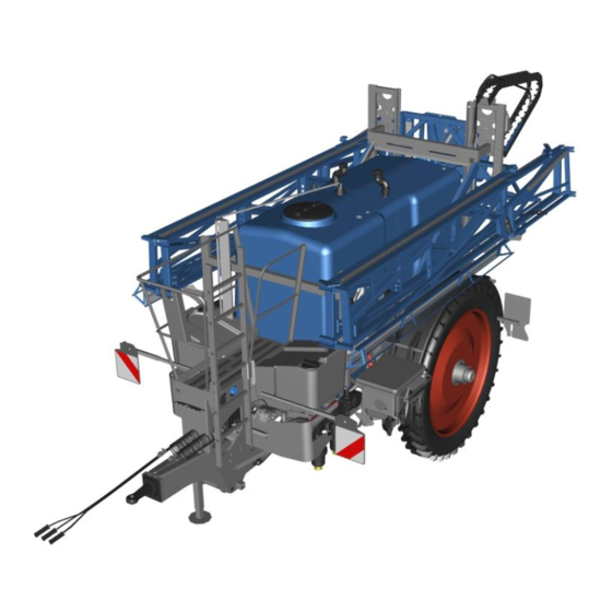
Page 33: Layout And Description
Layout and description LAYOUT AND DESCRIPTION Overview 1 Chassis with drawbar 7 Pump/Pumps 2 Drawbar end piece with 8 Control and connection centre drawbar eye 3 Axle 9 Chemical inductor 4 Wheels 10 Lift mast with pendulum system 5 Main tank 11 Rods 6 2 clean water tanks... -
Page 34: Chassis, General
The axle of the implement is implemented as a running axle or a braked axle. The permissible axle load is indicated on the Lemken axle type plate (1). The implement may only be used with a running axle if the empty weight of the tractor is at least double the permissible total weight of the filled implement. -
Page 35: Without Brake System
Layout and description 4.4.1 Without brake system For implements without brake systems, running axles or brake axles without actua- tion devices are used. Safety chain According to national regulations, a safety chain (1) may be required for implements without a brake system. The safety chain is only intended as a safety component. - Page 36 Layout and description Manual control (4) Double release valve (5) Emergency relay brake valve (6) Compressed air tank (7) Drain valve (8) Combo brake cylinder (9)
- Page 37 Layout and description Assembly The air brake system comprises the: Parking brake Service brake Shear brake The individual brake functions are acti- vated according to brake cylinder actuati- Parking brake The spring accumulators of the brake - cylinder are activated or released with the red button (1) of the double release valve.
-
Page 38: Air Brake System With An Automatic, Load-Dependent Compressed Air Brake Valve And Pneumatic Suspension
Layout and description With the black button (1) the service brake can be activated or released. The manual control (2) can be used to ad- just the braking force to suit the filling level of the device. Shear brake If the brake lines are interrupted when the device is disconnected from the tractor, emergency braking is automatically enga- ged, using the operating pressure of the... - Page 39 Layout and description The necessary brake pressure is automati- cally regulated depending on the control pressure and the setting of the automatic, load-dependent brake regulator (2). The implement is equipped with a level controller in order to maintain the height of the implement.
-
Page 40: Hydraulic Braking System
Layout and description The pneumatic suspension (1) is supplied with air via: a bypass valve (5) a second air tank (6) the air tank of the brake system (7). 4.4.4 Hydraulic braking system Only tractors that have a hydraulic braking system compatible with that of the imple- ment may be used to operate implements with a hydraulic braking system. -
Page 41: Liquid Flow
Layout and description Liquid flow 4.5.1 Overview 2500/3500 l 14 13 Clean water tank Canister rinsing nozzle Control valve Connection for cleaning gun Self-cleaning pressure filter Pressure control valve Flowmeter External cleaning Agitator Nozzle line Internal cleaning of main tank Part-width section valves Main tank Central bypass valve... -
Page 42: Description Of The Spraying Process Up To 3500 L
Layout and description Selection valve, spray pump Flush valve Switchover valve spraying agent / Drain valve pressure filter clean water Distributing valve Spraying pump Agitator control Suction valve 4.5.2 Description of the spraying process up to 3500 l During the spraying process, the spray pump (H) draws the spraying fluid from the main tank (7) via the switching valve (C), the selection valve (A) and the suction filter (9). - Page 43 Layout and description required by the nozzles to flow into the agitator (5) and/or into the suction circuit of the pump via the agitator regulator (E). If automatic metering is switched on in the control unit, the metering proceeds de- pending on the travel speed.
-
Page 44: Overview Of 4500 L
Layout and description 4.5.3 Overview of 4500 l 14 13 Clean water tank Canister rinsing nozzle Control valve Connection for cleaning gun Self-cleaning pressure filter Pressure control valve Flowmeter External cleaning Agitator Nozzle line Internal cleaning of main tank Part-width section valves Main tank Central bypass valve Drain valve... -
Page 45: Description Of The Spraying Pricess With 4500 L
Layout and description Selection valve, spray pump Flush valve Selection valve agitator pump Drain valve pressure filter Switchover valve spraying agent / Spraying pump clean water Distributing valve Agitator pump Agitator control Suction valve 4.5.4 Description of the spraying pricess with 4500 l During the spraying process, the spray pump (H) draws the spraying fluid from the main tank (7) via the switching valve (C), the selection valve (A) and the suction filter (9). -
Page 46: Liquid Flow To Nozzles
Layout and description The control valve (2) can be used to control the metering of the distribution rate. The control valve is operated by the control unit and allows the spraying fluid not required by the nozzles to flow into the agitator (5). If automatic metering is activated in the control system, metering is proportional to the speed of travel. - Page 47 Layout and description The spraying agent flows through the open central bypass valve (21) into the agi- tator via the bypass collector. Since the spraying fluid circulates through the pump(s), suction area, pressure range, sprayer boom and agitator when pumped into the tank, this prevents any spraying agent from settling in this pipe system.
-
Page 48: Main Tank
Layout and description Main tank The main tank is designed to hold water, sprays and fertilisers. The main tank is equipped with a tightly closed cover (1). Note: The tank opening is only intended for repair work. The level of the main tank is indicated on the indirect level indicator (2). -
Page 49: Clean Water Tank
Layout and description The drain valve (5) allows the contents of the main tank to be freely drained into a suitable collecting tank or sucked off with an external pump. Clean water tank The clean water tanks (1) are designed to hold clean water. -
Page 50: Hand-Wash Tank
Layout and description Hand-wash tank The hand-washing tank (1) is designed for receiving clean water. For example to faci- litate handwashing. Filter Functional and clean filters are a prerequi- site for trouble-free operation. The device comes complete with the follo- wing filters: ... -
Page 51: Control And Connection Centre
Layout and description 2 Drive 3 Intake connection 4 Pressure connection 5 Oil filling opening 6 Oil level indicator 7 Drain screw 4.11 Control and connection centre The following positional designa- tions correspond to the position markings of the fluid lines, see "Liquid flow, page 39". -
Page 52: Selector Valves
Layout and description 4.11.1 Selector valves Selection valve spray pump Pictogram Switch position Description Selector valve (A) is opened for the exter- nal connection. The main tank is filled externally using a pump and a suction hose. Selector valve (A) is switched to the swit- chover valve (C). -
Page 53: Distributing Valve
Layout and description 4.11.3 Distributing valve Pictogram Function Description Spraying The fluid is conveyed to the boom. The fluid is conveyed to the cleaning nozzles Internal cleaning in the main tank. The fluid is conveyed to the injector of the Washing-in chemical inductor and to the chemical induc- tor. -
Page 54: Chemical Inductor
Layout and description 4.11.5 Chemical inductor Spraying agents can be poured into the main tank via the induction gate. The in- duction gate comprises the following com- ponents: Container (1) The container can be swivelled in work- ing and transport positions. ... - Page 55 Layout and description Canister flushing nozzle (7) Empty spray agent canisters can be rin- sed out with the canister flushing nozzle. The cleaning intensity can be varied u- sing the valve canister flushing nozzle (3). Agitator nozzle (8) The agitator nozzle allows the spray agent to be dissolved and pre-mixed.
-
Page 56: Connections
Layout and description 4.11.6 Connections The following connections are available: Filling opening (1) of the handwashing container Filling opening (2) of the clean water - container Intake connection (3) External cleaning/pumping (4) Filling port (not shown) 4.11.7 Pressure limiting valve The pressure limiting valve (1) is used to adjust the maximum system pressure of... -
Page 57: Drain Valve Handwashing Tank
Layout and description 4.11.8 Drain valve handwashing tank The handwashing tank can be emptied via the drain valve (1). 4.11.9 Fill level indicator and TANK control The fill level indicator (1) is visible on the main tank. As an option, the contents of the main con- tainer can also be viewed in the control unit and at the control centre via a separa- te display unit (2). -
Page 58: Filling Hose Holder
Layout and description 4.12 Filling hose holder Water or spraying fluid can be extracted from external tanks via a filling hose. A holder (1) is also available for the filling hose. 4.13 Storage compartment There is a storage compartment on the right-hand side of the machine in the direc- tion of travel. -
Page 59: Flowmeter
Layout and description In the case of running axles (2), the speed is detected by means of an external sensor (3). The sensor (3) detects the bolts (4) on a disc (4) which is attached to the hub. The control terminal calculates the dis- tance and the speed of travel. -
Page 60: Pressure Measuring Device
Layout and description 4.16 Pressure measuring device The pressure measuring device is provided for monitoring the spray pressure (Automa- tic mode) and for the indirect indication of filter contamination. The pressure measuring device (1) mea- sures the spray pressure and displays this on the control terminal. -
Page 61: Operation Terminal
Layout and description 4.19 Operation terminal The LEMKEN CCI-50 operation terminal is used to operate the electronic control of the device For general operation of the CCI operation terminal, see separate operating instructions Competence Center ISOBUS e.V. 4.20 Height adjustment The height of the sprayer boom is adjusted via a hydraulic cylinder (1) on the lift mast. -
Page 62: Stabiliser
Layout and description 4.22 Stabiliser The stabiliser (1) damps the swing sus- pension and therefore provides a better position of the boom on slopes. 4.23 Segment valves Individual segments of the boom, or the complete boom can be switched on or off with the segment valves (1) on the boom. -
Page 63: Spacer
Layout and description 4.25 Spacer The spacers ensure the minimum distance to the ground is maintained when the spra- yer boom moves vertically. 4.26 Nozzle holders The unit can be equipped with the follo- wing nozzle holders: Single nozzle holder ... -
Page 64: Triple Nozzle Holder
Layout and description 4.26.2 Triple nozzle holder Up to three nozzles can be attached to each of the triple nozzle holders (3). The desired nozzle (1) is selected by turning the nozzle holder. Between the individual nozzles there is a locking position for closing the nozzle hol- der. -
Page 65: Drag Hose
Layout and description 4.28 Drag hose The drag hoses (1) are intended for the application of liquid fertilizer. Burning of foliage is hardly possible, due to the direct application onto the ground. 4.29 Spray cone lighting Spray cone lighting is intended to light the spray pattern under dark conditions. -
Page 66: Preparations
Preparations PREPARATIONS Preparations on tractor 5.1.1 Checking the suitability of the tractor for the implement Check the following before attaching the implement to the tractor: Check the required voltage sources Check the voltage sources of the tractor. A voltage source is available on the tractor for each device drawing power. - Page 67 Preparations If several devices drawing power are connected to a single socket: Please note that according to DIN 9680, the fuse protection must be at least 25 A per socket. Where applicable, use multiple sockets with separate fuses. ...
-
Page 68: Check Tractor Tire Pressure
Preparations Devices drawing power EW DW DR Sprayer boom height ad- Blue justment Sprayer boom flaps Green P2/T2 Yel- Electrohydraulic operation P6/T6 low/white Electrohydraulic operation EW = Single-acting control unit DW = Double-acting control unit DR = Pressure-free return flow LS = Load-Sensing signal cable 5.1.2 Check tractor tire pressure The air pressure in the tractor tyres must be identical, in particular, on the rear... -
Page 69: Installation Of The Operation Terminal
Preparations 5.1.3 Installation of the operation terminal Mount the holder for the operation termi- nal in the visible area and the user's grip area. Ensure that no electrical or fluid-carrying cables are damaged during drilling. WARNING: Damaged lines can lead to accidents. -
Page 70: Attaching The Implement
Preparations Attaching the implement Target: Device is fully available for distri- bution. Application: Before using ATTENTION: To protect the tractor and device, the latter is suspended in a hori- zontal position at a vertical angle of +/-5° to the tractor. ... - Page 71 Preparations Slowly and carefully, pull the tractor's trailer coupling up to the towing eye of the implement. ATTENTION: Do not slide the device in the process.If the device is on the sup- port legs, moving the device may dama- ge them.
-
Page 72: Conversion Of Device
Allow the height of the towing eye im- plement to be adjusted by re-screwing. Have other towing eyes approved by LEMKEN installed, see "Traction loops, page 181". In line with national provisions:Have the towing device and/or drawbar components replaced in the registration papers. -
Page 73: Check And Mount Cardan Shaft
Preparations 5.3.3 Check and mount cardan shaft Prerequisite: Device is coupled to the tractor. Check whether the length of the cardan shaft is suitable.Also check telescopic cardan shafts. The cardan shaft must not be com- pressed when pushed in (PuLz). ... - Page 74 Preparations Shortening a non-telescopic cardan shaft. Pull both PTO shaft halves apart. Keep both PTO shaft halves at the shor- test distance from tractor to implement. Mark the length to be cut off on the outer protective tube. ...
- Page 75 Preparations Ensure that the cardan shaft guard of the cardan shaft is secured with the chain (1) at a fixed point against rotating. Shortening a telescopic cardan shaft Special knowledge and tools are required to shorten a telescopic cardan shaft. Ac- cordingly, this task is best left to specialist service personnel.
-
Page 76: Determining The Filling Capacity Of The Implement
Preparations Determining the filling capacity of the implement To determine the permissible filling capacity of the implement [l/kg] the following data and procedures must be taken into account: Implement table Recording of data from Determination of the Determination of the the implement type plate data by weighing data by calculation... - Page 77 Preparations Example table Data recorded e.g. Determina- e.g. Determinati- e.g. from the type tion of the on of the da- plate data by ta by calcula- weighing tion Total permissib- Actual axle Permissible 3000 / 0.85 = le weight of im- load, imple- capacity of the 7500...
-
Page 78: Installation Of The Correct Nozzles
Preparations For spraying liquids with a higher density, e.g. AHL solution with 30 weight % (=density factor 1.3 [kg/dm³]) the higher density must be taken into account by reducing the filling quantity (e.g.: 1 l AHL / 1,3 = ~ 0.77 l/kg AHL → 3530 x 0.77 = ~ 2718 l AHL- filling quantity). - Page 79 Preparations The nozzles are mounted on the nozzle holders with bayonet caps. It is recom- mended that a separate set of bayonet caps is used for each set of nozzles. Be aware that different bayonet caps must be used for each type of nozzle. ...
- Page 80 Preparations Five-hole liquid fertilizer nozzles The five-hole nozzles are used in the following combination: Bayonet cap (1) Five-hole nozzle (2) Metering disc (3) Seal (4) Note the correct installation The arrow in the 2 following illustrations shows the direction of travel of the im- plement.
-
Page 81: Volumetric Metering Of The Nozzles And Calibrating The Flowmeter
Preparations Volumetric metering of the nozzles and calibrating the flowmeter Automatic control of the distribution rate [l/ha] is achieved via the travel speed and the flow of the spraying fluid through the nozzles. The spraying fluid flow rate de- pends on the selected nozzles and the spray pressure. -
Page 82: Volumetrically Meter The Nozzles
Preparations 5.6.1 Volumetrically meter the nozzles In order to determine the exact value of the nozzle output, at least 3 nozzles are remo- ved from different part-width sections. Preparations for the tractor-unit combination Fill the main tank with at least 500 l of clean water. - Page 83 Preparations Adjusting the control Select the manual mode to control the distribution rate in the control system. The work mask view changes. Determine the intended spray pressure of the built-in nozzles in the nozzle table. Start distribution. ...
-
Page 84: Calibrate The Flowmeter
Preparations If the output quantities of the measured nozzles are the same and the l/min value deviates from the value in the nozzle table: Adjust spray pressure. Example: According to the nozzle table, at 2.5 bar the nozzle output is 1.5 l/min. If the measured value is only 1.2 l/min, spray pressure is increased until the in- tended single nozzle output of 1.5 l/min... -
Page 85: Calibration Of The Speed Sensor
Preparations Calibration of the speed sensor 5.7.1 Check speed sensor For automatic metering with the operation terminal, the distance impulses have to be taken from the device and calibrated to 100 m. Before calibration, check that the speed sensor (1) on a device with a running ax- le is located 5 - 10 mm from the screws (2) of the pulse disc (3). -
Page 86: Check Compatibility Of Pesticides With Equipment
Preparations Check compatibility of pesticides with equipment Specially approved pesticides and mixed - compounds may have an adverse effect on the device materials. This applies in parti- cular to spraying agents containing sol- vents and mixed compounds. The following parts of the device may be affected by damage: ... -
Page 87: Operation
Operation OPERATION Prepare device for use 6.1.1 Adapt device for use Target: The external conditions and equipment of the device are appropriate for the intended use. Check the following before distribution and adjust if necessary: Check whether the unit contains anti- freeze. -
Page 88: Prepare The Device For Operation In Frosty Conditions
Operation 6.1.2 Prepare the device for operation in frosty conditions Risk of accident due to frozen braking system of the device WARNING If the braking system of the device is frozen, it is no longer possib- le to brake the device. This may even be fatal or result in serious injuries. -
Page 89: Fill Device With Liquids
Operation 6.1.3 Fill device with liquids Target: All the necessary liquids are available for use. Fill the following containers with liquids: Fill the handwash container with water, see "Filling hand-washing container, pa- ge 88". For cleaning purposes on the fieldFill the clean water tank with water, see "Filling the clean water tank, page 89". -
Page 90: Filling And Emptying The Hand-Washing Container
Operation Filling and emptying the hand-washing container The hand-washing container is intended exclusively for cleaning purposes and is not suitable for housing cleaning agents and sprays. CAUTION: Germs or traces of cleaning agents and sprays may contaminate the hand-washing container. ... -
Page 91: Filling And Emptying The Clean Water Tank
Operation Filling and emptying the clean water tank The unit is equipped with two interconnec- ted clean water tanks. The clean water tanks are intended for cleaning purposes. The entire piping sys- tem and the device functions are designed to fill the clean water tanks exclusively with clean water. -
Page 92: Emptying The Clean Water Tank
Operation 6.3.2 Emptying the clean water tank To ensure no vacuum when emptying the clean water tank:Before emptying check whether the ventilation valves (2) are functional. Unscrew and remove the union nut (4) of the connecting hose. The water runs out of the clean water tanks. -
Page 93: Standard Procedure
Operation 6.4.1 Standard procedure Prerequisite: The drain valve (1) is closed and secured with the blind cap (2). Read the usage instructions for the spraying agent. Observe the respective national regula- tions and standards regarding the hand- ling of spraying agents: e.g. water pro- tection zones, filling of equipment etc. -
Page 94: External Filling Connection
Operation 6.4.2 External filling connection Application: Pump water or ready-mixed spraying fluid with an external pump into the main tank. Remove the blind cap (1) of the filling connection. Attach the filling hose (2) to the filling port. ... - Page 95 Operation After filling the main container: Set the filling valve (3) to close. Remove filling hose. Close the filling port with the blind cap (1). spraying fluid can also be pumped into the main tank via the filling connection with an external pump.
-
Page 96: Intake Connection
Operation 6.4.3 Intake connection Application: Pump water or ready-mixed spraying fluid with the intake connection into the main tank. The maximum suction depth with a filling hose is 2.5 m. *Position designations correspond to the position de- signations of the fluid lines, see "Liquid flow, page 39". Approach* ... - Page 97 Operation Set agitator regulation (E) to maximum. Switch diverting valve to spraying mode. Monitor the filling of the main tank with the following aids: Fill level indicator (4) Display unit at the operating and ad- justment centre ...
-
Page 98: Chemical Inductor
Operation 6.4.4 Chemical inductor Application: Rinse unmixed or ready- mixed spraying fluid into the main tank. Prerequisite: The main tank is filled with water or fertilizer solution according to the instructions of the respective spray agent manufacturer. Fold the lever (1) on the induction lock upwards. - Page 99 Operation The supplied measuring cup can be used to measure and dose the spray agent. For measuring and dosing the spray agent: Place the measuring cup (4) in the holder (5). Swivel the cover (6) upwards to open it. ...
- Page 100 Operation Fill the spray agent into the induction va- lve. Match the suction quantity, edge mois- tening and intensity of the agitator nozz- le to each other: To prevent the induction gate overflo- wing: Set the suction volume via the suction valve.
-
Page 101: Adjust Flush Valve
Operation Switch diverting valve to spraying mode. Stir spraying agent, see "Working with the device, page 111". Adjust the agitator control output accord- ingly. Adjust flush valve Targets: Pressure filter does not clog. Flushing valve adjustment (1) matches distribution rate[l/ha]. - Page 102 Operation Preconditions: Control is set on the basis of the instal- led nozzles and the corresponding do- sing table. The intended travel speed (km/h) and spray rate (l/ha) are known. The required spray pressure is deter- mined. ...
-
Page 103: Cleaning Empty Canisters
Operation On the implement: Turn the flush valve (1) so that the required spray pressure is indicated in the control unit. Cleaning empty canisters Spraying agent may cause damage to health and pollute the environment. CAUTION If the lever of the cleaning nozzle is not closed, you may by spra- yed by the cleaning nozzle. - Page 104 Operation Open the suction valve so that the liquid which flows out of the spraying agent canister is directly sucked out. The escaping liquid must not overflow from the induction hopper. After cleaning the spraying agent canister: Close the cleaning nozzle lever. ...
-
Page 105: Cleaning Gun On The Induction Hopper
Operation It may be possible to return empty, clean canisters to the supplier of the spraying agent. Please ask your spraying agent supplier. If a return is not possible: Recycle the empty, clean spraying agent canisters. Cleaning gun on the induction hopper ... - Page 106 Operation Remove the cleaning gun (1) from the holder (2). Switch the distributor valve to the induc- tion hopper. Switch the cleaning gun lever up to ON. The effect of the cleaning gun can be con- tinuously regulated with the lever (1). ...
-
Page 107: Flushing The Induction System
Operation Clean empty canisters or the induction hopper container. After cleaning: Close the cleaning gun lever by swit- ching it down to OFF. Place the cleaning gun in the holder (2). Because of the limited content of the fresh water tank we recom- mend that ... - Page 108 Operation Close the cover (1) of the induction con- tainer. To flush the induction system, switch the following levers up into the ON position: Canister flushing nozzle Edge wetting Agitator nozzle Open the suction valve so far that no li- quid can escape from the induction con- tainer.
-
Page 109: Folding Out Sprayer Boom
Operation Close the suction valve. Switch the selector switch to the main tank. Switch the distributor valve to spraying. Because of the limited content of the fresh water tank we recom- mend that for the cleaning of empty spraying agent canisters or ... -
Page 110: Standard Procedure
Operation 6.9.1 Standard procedure Make certain the tractor is stopped. Travel speed = 0 km/h Make certain there are no overhead lines in the folding range. DANGER: If the implement touches an overhead line during excavation there is a danger of fatal electric shock. -
Page 111: Adjusting The Spring Stabiliser
Operation 6.10 Adjusting the spring stabiliser The spring stabiliser can be adjusted to suit the terrain. In the basic setting of the spring stabiliser, 15 chain links (1) are attached. Right hand stabilising chain Left hand stabilising chain Terrain Damping Stabilising chain Steep slope with firm Stronger... -
Page 112: Trial Operation Of Device
Operation 6.11 Trial operation of device Applications: Initial start-up Getting to know the individual control functions Before initial use with spraying agents After maintenance operations After repairs Put the ladder in the transport position: ... -
Page 113: Working With The Device
Operation Perform trial spraying operation: Switch on the nozzles. Work with the device, see "Working with the device, page 111". Check all components for function and leak tightness. Check spray result. 6.12 Working with the device Preconditions: ... -
Page 114: Prepare For Distribution
Operation 6.12.1 Prepare for distribution Fold out sprayer boom, see "Folding out sprayer boom, page 107". Adjust pendulum system. Adjust stabiliser. Set selection valve to main tank. Set diverting valve to spray mode. Adjust the agitator control to the agitator intensity according to the usage instruc- tions of the spraying agent used. -
Page 115: Apply Spraying Agent
Operation 6.12.2 Apply spraying agent Bring the tractor-device combination into position. Spraying: Move over the processing area with the tractor-device combination. Switch on the nozzles. During distribution, drive at a speed that matches the installed nozzles and the distribution rate set. - Page 116 Operation When the machine drifts outside the de- signated track, for example on a side slope: Go into reverse with the tractor. When pressure fluctuations occur when the main tank becomes empty: Interrupt distribution. Refill device.or ...
-
Page 117: Working On Rugged Terrain Or On A Slope
Operation 6.13 Working on rugged terrain or on a slope By changing the centre of gravity to com- pensate for a slope, the position of the boom can be adjusted to adapt to rugged terrain or a slope so it is parallel to the ground. - Page 118 Operation Rotate nozzle holder to an open positi- For sprayer booms with multiple nozzle holders (4) in which all nozzle holder po- sitions are fitted with nozzles, remove one bayonet cap with nozzle (5) for each. Install drop hoses (6) with the inserted seals and metering washers (7) on the nozzle holders.
-
Page 119: Spraying With Drop Hoses
Operation 6.15.2 Spraying with drop hoses So that the water from the drop hoses bet- ter penetrates the soil and to prevent the hoses from being pulled over the ground: drive slowly. 6.16 Fold in sprayer boom Applications: Before driving on the road ... -
Page 120: System Cleaning With Partially Filled Main Container
Operation Raise the sprayer boom to the stops (1). ATTENTION: The sprayer boom swings when the device moves.When the spra- yer boom reaches the topmost position on the lift mast, the sprayer boom is rea- ligned. Fold in the sprayer boom with the tractor control unit. - Page 121 Operation General procedure: Rinse the piping system prior to interrup- tion. Stir spraying fluid before resuming distri- bution. System cleaning conditions for partially filled main tank: The concentration of the spray agent remains unchanged. No clean water flows into the main tank. ...
-
Page 122: Flush The Pipe System Before Interruption
Operation 6.17.1 Flush the pipe system before interruption Description* * Position designations correspond to the position designations of the fluid lines. The spray pump (H) draws the water from the clean water tank via the switching val- ve (C), the selection valve (A) and the suc- tion filter (9). - Page 123 Operation Procedure Switch off pump (H) via PTO shaft. Close flushing valve (F). Remember the number of turns to close the valve. This adjustment is required after the sys- tem has been cleaned. Switch the selection valve of the spray pump (A) to change-over valve (C).
- Page 124 Operation During the distribution: Move with increased travel speed. Open and close part-width section va- lves (20) with switchbox. ATTENTION: Only switch the part-width section valves.If the nozzles are swit- ched off via the control unit, the central bypass valve (21) opens and the water is pumped into the main tank.
-
Page 125: Stir Spraying Fluid Before Distribution
Operation 6.17.2 Stir spraying fluid before distribution Target: To keep the piping system and nozzles functioning and prevent blockage due to decomposed spray solution. Application: Distribution continued after an interruption. Prerequisite: To ensure the correct con- centration of the spraying fluid, do not spray while stirring. - Page 126 Operation The spray pump (H) draws the spraying fluid from the main tank (7) via the swit- ching valve (C), the selection valve (A) and the suction filter (9). The spraying fluid is pumped to the closed part-width sections via the diverting valve (D). The spraying fluid continues to flow through the central bypass valve (21) into the agitator (5).
- Page 127 Operation Switch the agitator regulation (E) to ma- ximum agitator action. Observe the instructions for use of the spraying agent used. Switch on the pump (2500/3500 l = H | 4500 l = I) via the pump nozzle. ...
-
Page 128: Cleaning
Cleaning CLEANING Standard procedure Remaining quantities of spraying agent must not be drained off at ATTENTION the edges of the road or discharged into the sewer system. Where possible: Reuse collected spraying agent (after consul- ting the respective spraying agent manufacturer). ... - Page 129 Cleaning The following should be noted during the cleaning: Regulations of the spraying agent manu- facturer Regulations of the nozzle manufacturer These operating instructions Other regulations for handling spraying agents Standard procedure: Emptying main container, see ", page 128".
-
Page 130: Emptying The Main Tank
Cleaning Emptying the main tank 7.2.1 General If the content of the main tank cannot be properly sprayed, the spraying agent is to be disposed of in the proper manner. To empty the main tank the spraying agent must be pumped into an external tank, ... -
Page 131: Draining Spraying Agent Out Of The Main Tank
Cleaning To pump out the remaining quantity: Switch on pump via PTO shaft. Operate the pump at the specified speed. After pumping out: Switch off pump via PTO shaft. Remove hose. Close pump connection with sealing cap. After the remaining quantity has been pumped out, internal cleaning is necessa- ry, see "Internal cleaning, page 130". -
Page 132: Internal Cleaning
Cleaning Close the drain valve (2). Replace the screw cap (3). Check that the connector does not leak. Carry out internal cleaning, and external cleaning and filter cleaning if necessary. Internal cleaning ATTENTION Deposits from the spray solution contaminate the main tank, the piping system and the nozzles. -
Page 133: Standard Procedure
Cleaning Additional information: Depending on the pesticide and subsequent intended use, the main container, piping system and nozzles may have to be cleaned with cleaning agents.Please refer in this case to the operating instructions for the pesticide products and cleaning agents used. 7.3.1 Standard procedure Preconditions: ... -
Page 134: Clean Main Container
Cleaning Reduce spray pressure. Move with increased travel speed. Open and close part-width section va- lves (20) with the switchbox. Spray out the contents of the main tank: Until air comes out of the nozzles. ... - Page 135 Cleaning Device with 2500/3500 l: * Position designations correspond to the position designations of the fluid lines.
- Page 136 Cleaning After the main tank (7) has been filled with water, the switchover valve (C) is switched to the main tank. The spray pump (H) draws the spraying fluid from the main tank (7) via the swit- ching valve (C), the selection valve (A) and the suction filter (9).
- Page 137 Cleaning Procedures Preconditions: Adjustments, see "Internal cleaning, pa- ge 130" Nozzles are switched off. At the control centre, the selection valve (A) is switched to a change-over valve (C). For a device with 4500 l:Selection valve (B) is switched to main tank. ...
-
Page 138: External Cleaning
Cleaning External cleaning Target: Clean equipment, unintentional dripping or discharge of adhesive spray agent is prevented. Applications: If the device is contaminated with spraying agent. When changing spraying agent, if the spraying agent impacts on the next surface to be sprayed. ... -
Page 139: Prepare External Cleaning
Cleaning 7.4.1 Prepare external cleaning Park the tractor-unit combination on an unsealed area. Wear protective equipment. When cleaning agent is used: Observe the instructions for use of the spraying agent and the cleaning agent. Switch off the operation terminal. ... -
Page 140: Cleaning The Filter
Cleaning Spray device with the spray gun. Press handle = water sprays as long as the handle is pressed. Fix the pressed handle with a ram (5) = water sprays until the fixation is lif- ted. Pressing the handle again releases the locking of the ram. -
Page 141: Standard Procedure
Cleaning 7.5.1 Standard procedure To remove particles of dirt from the sys- tem: Close flushing valve before the final day of spraying. Check whether the pump is switched off via the PTO shaft. Place a collection tray (1) under the filter before cleaning. -
Page 142: Pressure Filter
Cleaning When mounting, ensure the seal (4) is correctly inserted and not crushed. 7.5.3 Pressure filter Preconditions: Nozzles are switched off. The diverting valve is switched to exter- nal cleaning/pumping. Connection for external cleaning/ pum- ping is sealed with a sealing cap. ... - Page 143 Cleaning Procedure Loosen the union nut (2) of the pressure filter. Remove the pressure filter. Clean the individual components with water and a soft brush. Install pressure filter. When mounting, ensure the seal (3) is correctly inserted and not crushed.
-
Page 144: Uncoupling The Implement
Uncoupling the implement UNCOUPLING THE IMPLEMENT Preparations Target: The device is safely stored un- derneath until the next use. Applications: After one use For wintering Preconditions: All containers are empty. Device is cleaned, see "Cleaning, page 126". -
Page 145: For Wintering
Uncoupling the implement Activate the parking brake of the tractor. Switch off the tractor engine. Remove the ignition key. Secure the tractor to prevent it from rol- ling away. 8.1.2 For wintering Target: Ensure the device is protected against frost damage. -
Page 146: Put Device Into Park Mode
Uncoupling the implement Provide biodegradable antifreeze. ATTENTION: Do not use liquid fertiliser. Liquid fertiliser will damage the rubber components. Observe the operating instructions and the safety data sheet of the antifreeze agent. All fluid-carrying parts: Drying ... -
Page 147: Remove Safety Chain
Uncoupling the implement 8.2.2 Remove safety chain Only for a device without a braking system: Push bolt (1) of the safety chain inwards. Unlock the bolt (2): Press the bolt against the hook (3). Or cross ledger (2). ... -
Page 148: Detaching The Implement
Uncoupling the implement Detaching the implement Uncouple the brake lines from the trac- tor. For hydraulic braking system: Attach the brake line to the holder on the device si- Uncouple the cardan shaft from the trac- tor. ... -
Page 149: Maintenance And Servicing
Maintenance and servicing MAINTENANCE AND SERVICING Safely maintain the device Personnel For certain activities, e.g. braking system work, service personnel (e.g. in agricultural machinery workshops) are required. These activities are marked in the maintenance schedule. Preparations Switch off the device. ... -
Page 150: Environmental Protection
Maintenance and servicing During the maintenance and repair To prevent accidents and injuries: Wear protective equipment. Use the following instruments: Suitable tools Climbing aids Supporting elements For dismantling and mounting heavy components:Use hoisting gear. ... -
Page 151: Maintenance Intervals
Maintenance and servicing Maintenance intervals Interval Activity Hose connections Pins, bolts etc. Piston rods hydraulic cylinder Slide pipes Cardan shaft Joints Traction loop Parking support Rope Axle slack adjuster Axle camshafts Ladder Lift mast Self-aligning bearing Carriage guide Pendulum guidance Cable pulley Sprayer boom Bolted connections... -
Page 152: Oils And Lubricants
Maintenance and servicing Interval Activity Pump Pressure accumulator, pump Axle Braking system Oils and lubricants Amount per maintenan- Assembly group Oil / lubricant ce interval Grease nipple and open Multi-purpose grease Depending on the lubrica- lubrication points tion points Sliding areas on the lift mast OKS Mox-Active 451 As required Piston rods on the hydraulic... -
Page 153: Lubricating
Maintenance and servicing Lubricating Eye injuries due to grease When lubricating the lubrication points, grease can escape WARNING between components at high pressure and cause injury to the eyes. When lubricating components, wear protective clothing, especi- ally safety glasses. ... -
Page 154: Traction Loop
Maintenance and servicing 9.4.2 Traction loop Lubrication interval: Every 8 operating hours Lubricate contact surface of the traction loop (1). 9.4.3 Stand Lubrication interval: Every 8 operating hours Lubricate grease nipple (1). -
Page 155: Slack Adjuster
Maintenance and servicing 9.4.4 Slack adjuster Lubrication interval: Every 8 operating hours Lubricate grease nipple (1). 9.4.5 Camshaft Lubrication interval: Every 8 operating hours Lubricate grease nipple (1). -
Page 156: Lift Mast And Self-Aligning Bearings
Maintenance and servicing 9.4.6 Lift mast and self-aligning bearings Lubrication interval: Every 8 operating hours Lubricate both sliding surfaces on the lift mast (1) using a brush. Lubricate the four sliding surfaces on the lift mast (2) using a paintbrush. To lubricate these sliding surfaces, use chain and adhesive lubricant OKS Mox-Active 451. -
Page 157: Skids And Pivoted Guide
Maintenance and servicing 9.4.7 Skids and pivoted guide Lubrication interval: Every 8 operating hours Lubricate the grease nipple on the self- aligning bearing (1). Lubricate both the right and left grease nipples on the pivoted guide (2). ... -
Page 158: Cable
Maintenance and servicing 9.4.9 Cable Lubrication interval: Every 50 operating hours After cleaning, lubricate the ropes with lubricant for wire ropes. 9.4.10 Sprayer boom Lubrication interval: Every 8 operating hours The following lubrication points are located on the right and left side of the boom. Images with the lubrication points are only shown from one side of the boom. - Page 159 Maintenance and servicing Pivot joint 1 Lubricate 4 grease nipples on pivot joint 1 (1). Pivot joint 2 Lubricate 4 grease nipples on pivot joint 2 (1). Lubricate 2 grease nipples on strut (2).
- Page 160 Maintenance and servicing Lubricate 4 grease nipples on the folding lever (3). Folding cylinder Boom with 2 folding cylinders: Lubricate each of the 2 grease nipples on the piston bottom (1) and on the pis- ton rod (2) of the folding cylinder (1) every 8 operating hours.
- Page 161 Maintenance and servicing Pivot joint 3 Lubricate 4 grease nipples on folding le- ver 3 (1). Lubricate 4 grease nipples on the folding lever 2 (2).
-
Page 162: Chemical Inductor
Maintenance and servicing 9.4.11 Chemical inductor Lubrication interval: Every 8 operating hours Lubricate the 4 grease nipples on the holder (1). Drive shaft Use lithium-lubricated grease, consistency class NL-G12. The drive shaft must be serviced on the tractor side and the implement side. Protective tube Safety chain Sliding tube not illustrated (inside the... -
Page 163: Protective Tube
Check hydraulic pipelines for damage and leaks. Replace damaged or faulty hydraulic ho- ses immediately. Check the manufacturing date of the hydraulic hoses. Replace after 6 years at the latest. Only use hydraulic hoses approved by LEMKEN. -
Page 164: Air Brake
Maintenance and servicing Air brake 9.7.1 General The air filter (1) of the air brake must be cleaned regularly. Park the implement on a level surface. Activate the tractor parking brake. Switch off the tractor engine. Remove the ignition key. 9.7.2 Bleeding ... -
Page 165: Cleaning
Maintenance and servicing 9.7.3 Cleaning DANGER Persons can be injured by the spring pressure of the air filter. Take care that there are no persons in the danger area. Due to the spring pressure of the air filter, the components of the air filter may fall onto the ground in an uncontrolled manner. -
Page 166: Tightening Torques
Maintenance and servicing Switch on the tractor engine. When the tractor engine is running, the brake system will automatically be filled with air. Check the seal of the air filter by listening for escaping air and with leak detector spray ... -
Page 167: Bolts And Nuts Made Of Steel
Maintenance and servicing 9.8.2 Bolts and nuts made of steel Strength category Diameter 8.8 [Nm*] 10.9 [Nm*] 12.9 [Nm*] 13,6 16,3 23,4 32,9 39,6 M 10 46,2 64,8 77,8 M 12 80,0 M 14 M 16 M 20 M 24 1112 M 30 1314... -
Page 168: Wheel Nuts
Maintenance and servicing Diameter [Nm] M 22 M 24 M 27 9.8.4 Wheel nuts The tightening torque for the wheel nuts (1) with centring spring ring (2) is 550 Nm. Remove the protective caps (3). Check the torque of the wheel nuts (1) ... -
Page 169: Check The Connections To The Tractor
Maintenance and servicing Check the connections to the tractor 9.9.1 Hydraulic connections Risk of accidents due to escaping hydraulic fluid Hydraulic fluid which is ejected under high pressure (hydraulic oil) WARNING can penetrate the skin and cause serious injuries. In the event of injuries, consult a doctor immediately. -
Page 170: Pump
Maintenance and servicing 9.10 Pump 9.10.1 General information Requirement for pump operation: Sufficient oil Correct pressure at the pressure ac- cumulator Proper membranes Properly functioning valves Annual maintenance performed by a quali- fied and well-trained person: ... -
Page 171: Check Oil Level
Maintenance and servicing 9.10.2 Check oil level The oil level of the pump is checked at the sight glass during operation. WARNING: A cardan shaft drives the pump.Persons may be entangled, pulled in and seriously injured by the cardan shaft. ... -
Page 172: Refill Oil
Maintenance and servicing 9.10.3 Refill oil To refill with oil safely: Switch off the PTO shaft. The cardan shaft is stationary. Switch off tractor engine. WARNING: When the tractor engine is switched on, the PTO shaft can be en- gaged even though another person may have to refill the oil. -
Page 173: Replace Membranes
Maintenance and servicing 9.10.4 Replace membranes If the oil in the sight glass is discoloured white, this indicates damage to the pump membranes. In the event of white discoloration of the oil, stop spraying immediately. CAUTION: Continuing to operate the pump will lead to it being damaged. -
Page 174: Check The Pressure At The Pressure Accumulator
Maintenance and servicing 9.10.5 Check the pressure at the pressure accumulator Check the pressure (1) at the pressure accumulator If the pressure measuring device of the instrument shows strong vibrations If the pressure hoses of the device vibrate strongly ... -
Page 175: Calibrating The Sensors
Maintenance and servicing Alternative Fill the pressure accumulator (1) to ap- prox. 10 bar. Operate the pump at the specified speed. Observe the pressure hoses of the pump. If the pressure hoses vibrate, or the pressure of the pressure measuring sys- tem varies significantly, relieve thepres- sure using a filling device with a tyre in- flation valve. -
Page 176: Filter
Maintenance and servicing 9.12 Filter Clean filters are a prerequisite for smooth operation. Therefore, the given filters must undergo regular maintenance. The use of pressure and nozzle filters with 80 meshes/inch or more may result in spraying agent being filtered out for some CAUTION spray agents. -
Page 177: Inspection Of The Implement
Maintenance and servicing 9.13.3 Inspection of the implement Every 2 years, have the following work carried out by a qualified, authorised person: measurement of the pump output measurement and calibration of the flow meter measurement of the pressure sensor 9.14 Control connections To check the implement as part of an offi-... -
Page 178: Pressure Gauge
Maintenance and servicing Pumps for tank volumes 4400 l: Connection (2) for reading pump perfor- mance. Connection (3) for reading the stirring per- formance 9.14.2 Pressure gauge Connection (1) for reading the pressure gauge. -
Page 179: Flowmeter
Maintenance and servicing 9.14.3 Flowmeter Connection (1) for reading the flowmeter. 9.15 Information in case of faults and malfunctions Fault Reason Remedy Slow, continuous pressure Dirty pressure filter Clean the pressure increase with constant appli- filter cation quantity (l/ha) White colouring of the oil in Diaphragms defective Stop spraying imme- the pump... -
Page 180: Technical Data
Technical data TECHNICAL DATA 10.1 Dimensions... -
Page 181: Weight
Technical data Length (L) Width (W) Height (H) [mm] [mm] [mm] Device base Minimum Maximum Minimum Maximum Minimum Maximum B 21 5300 5600 2600 2900 3300 3600 2500 B 27 5600 5900 2600 2900 3300 3600 B 30 5600 5900 2600 2900 3300... -
Page 182: Drawbar
Technical data The maximum payloads of the device are listed on its type plate. If the load capacity of the wheels is lower than the stated axle loads, the per- missible axle load shall be reduced in accordance with the load capacity of the wheels, taking into account the permissible maximum speed. -
Page 183: Traction Loops
10.4 Traction loops Only LEMKEN-approved traction loops may be used. Traction loops must satisfy the following minimum technical requirements: Drawbar load [kg]: 2000 D-value [kN]: 56.32... -
Page 184: Tyres
Technical data The implement may only be used with a running axle if the empty weight of the towing tractor is at least double the permissible total weight of the filled implement. The towing tractor must have sufficient braking capacity for the implement and the tractor. -
Page 185: Use Of Own Wheels Or Wheels Which Are Not Listed In The List Of Wheels
Technical data Size 460/85 R38 5.450 4.50 (18.4 R38) 460/85 R42 6.440 6.210 5.800 4.50 (18.4 R42) 520/85 R38 6.440 6.210 5.800 3.60 580/70 R38 8.880 8.560 8.000 4.60 (1) The maximum permissible air pressure is required for the maximum load capacity of the ty- res. - Page 186 Technical data Furthermore, it must be taken into account that the axle and braking system may need to be converted if wheels other than those delivered are fitted. The driving and braking characteristics of the implement due to conversion of the wheels must be examined by an expert.
-
Page 187: Rims
Technical data 10.8 Rims The implement's rims have a bearing load ≥ than the tyres used. The rim offset is +ET 70 or +107 (at a rim strength of 13 mm). The rims can be used on both sides. The rims have the following specifications: 10/280/335/ET+70: 10 Number of drill holes for wheel nuts (piece) 280 Ø... -
Page 188: Drive Shaft
Technical data Alternative track width The track change results in an alternative track width. Because of this, two diffe- rent track widths can be used for the implement. It must be taken into account that the clearance from the implement is limited. The maximum tyre width which re- sults from this limited clearance is listed as the maximum permissible tyre width in the corresponding table in these operating instructions. -
Page 189: Pumps
Technical data 10.11 Pumps Device Working pump Agitator pump 2500 P260 3500 P260 4500 P200 P200 Data per pump Type P 260 P 200/P200 PTO shaft DIN 9611 / ISO 500 Design Piston diaphragm pump Number of pistons 2 x 4 Connection Hose ... -
Page 190: Spraying Fluid System
Technical data Type P 260 P 200/P200 Rated speed [rpm] Speed range [rpm] 450 - 700 Volumetric flow at 5 bar and rated speed [l/min] Power consumption[KW] at rated speed 10.2 and 5 bar Oil type SAE 15W40 Approximate oil quantity [l] 2 x 1.3 Approximate weight [kg] 56.0... -
Page 191: Oil Hydraulic System
Technical data Filling connection, capacity Maximum filling capacity [l/min]: Maximum filling pressure [bar]: Suction connection, capacity Maximum vacuum pressure [bar]: - 0.3 Maximum suction height [m] Minimum suction hose diameter [mm]: Maximum suction hose length with hose at ground level [m]: Filler hose Connection to implement: 2"... -
Page 192: Pressure Limit Valves
Technical data 10.13.3 Pressure limit valves The pressure limit valves are factory set to 150 bar and may not be adjusted. 10.14 Electronic pressure display Type: Liquid crystal display Pressure detection: electronic pressure sensor in the pipe cross-section of the boom Accuracy class: 1.6% of displayed value... -
Page 193: Sprayer Boom
Technical data If the load capacity of the wheels is lower than the permissible axle load, the permissible axle load shall be reduced to the permissible load capacity of the wheels. Please note that when spraying heavier agents (e.g. AHL) the filling quantity of the containers must be reduced. -
Page 194: B27
Technical data 10.17.2 (1) From left to right // = Reduction Sprayer boom FS 15/00 – 7 B27 2.40 1/2/3x3/2/1 FS 18/00 – 7 B27 2.40 1.5/5x3/1.5 FS 18/00 – 9 B27 2.40 1/2/1.5/3x 3/1.5/2/1 FS 21/18 – 9 B27 2.40 1/2/5x3/2/1 FS 24/18 –... -
Page 195: B30
Technical data 10.17.3 (1) From left to right // = Reduction Sprayer boom FS 24/20 – 9 B30 2.70 2/2x2.5/3.5/3/ 3.5/2x2.5/2 FS 27/20 – 9 B30 2.70 1.5/2/4/4.5/3/ 4.5/4/2/1.5 FS 28/20 – 9 B30 2.70 2x2/4/4.5/3/ 4.5/4/2x2 FS 30/20 – 9 B30 2.70 2x2.5/4/4.5/3/ 4.5/4/2x2.5... -
Page 196: Appendix
Appendix APPENDIX 11.1 General information about nozzles Each nozzle type has a different volume flow, spray pattern, drop size and nozzle characteristics. The liquid to be sprayed, the environmental conditions, the nozzle characteristics and official regulations such as distance conditions, drift reduction classes etc. -
Page 197: Nozzle Tables
Appendix Spray height Optimum Pressure Optimum Spray above Designation Material (1) spray height Size (2) range spray pres- angle target area (cm) (bar) sure (bar) (cm) AGROTOP TD-HiSpeed Cer. 110° 40 - 60 .015 -. 05 2 - 10 4 - 8 Liquid fertiliser nozzles LECHLER FD 130º... -
Page 198: Nozzle Sizes 06 - 10
Appendix Nozzle spacing: 50 cm l/ha Flow 100 125 175 200 225 250 300 350 400 500 l/min 31.2 25.0 20.8 17.8 15.6 13.9 12.5 10.4 8.9 6.2 2.60 32.4 25.9 21.6 18.5 16.2 14.4 13.0 10.8 9.3 6.5 2.70 33.6 26.9 22.4 19.2 16.8 14.9 13.4 11.2 9.6 6.7 2.80... -
Page 199: Dosage Tables For Liquid Fertilisers
Appendix For conversion: Volume flow of water Correction fac- actual volume flow of (value on the basis of wa- the spraying liquid ter with density 1.0) After calculation of the actual volume flow of the spraying liquid, adjustment of im- plement and the output of the individual nozzles can be obtained from the dosage table. - Page 200 Appendix Water [l/ha] at 50 cm nozzle spacing Nozzle Pressure [l/min] [km/h] (Colour) [bar] nozzle 0.87 87.0 65.3 52.2 (Dark blue) 1.00 75.0 60.0 1.10 82.5 66.0 1.18 88.5 70.8 1.31 98.3 78.6 1.17 87.8 70.2 (Red) 1.33 99.8 79.8 1.45 87.0 1.55...
-
Page 201: Dosage Table, Five-Hole Nozzle Fl
Appendix Water [l/ha] at 50 cm nozzle spacing Nozzle Pressure [l/min] [km/h] (Colour) [bar] nozzle 4.09 1227 (Light green) 4.82 1446 5.40 1620 1080 5.87 1761 1174 6.58 1974 1316 Notes: Spray height above the crop 75 - 100 cm. ... - Page 202 Appendix [l/min] UAN [l/ha] Metering Pres- washer sure [km/h] H²O Ø/mm [bar] 0.31 0.27 0.43 0.38 0.8/32 0.53 0.47 0.62 0.55 0.69 0.61 0.46 0.41 0.65 0.57 1.0/39 0.80 0.71 0.92 0.81 1.03 0.91 0.67 0.59 0.95 0.84 1.2/48 1.16 1.03 1.34 1.18...
-
Page 203: Uan Dosage Table (28/1.28 Kg/L) For Nozzles Id, Idn, Idk, Idkn And Fd
Appendix 11.5.3 UAN dosage table (28/1.28 kg/l) for nozzles ID, IDN, IDK, IDKN and FD l/min UAN l/ha Pres- Nozzle (Co- sure km/h lour) [bar] -015 0.42 0.37 (Dark 0.48 0.42 green) 0.54 0.48 0.59 0.52 0.68 0.60 0.56 0.49 (Yellow) 0.65 0.57... - Page 204 Appendix l/min UAN l/ha Pres- Nozzle (Co- sure km/h lour) [bar] 1.14 1.00 (Brown) 1.39 1.22 1.61 1.42 1.80 1.58 1.97 1.73 2.28 2.01 1.67 1.47 (Grey) 1.93 1.70 2.16 1.90 2.36 2.08 2.73 2.40 2.23 1.96 (White) 2.58 2.27 2.88 2.53 3.16...
-
Page 205: Dosage Table, Liquid Fertiliser Nozzle Fd
Appendix (*) 1.0 bar applies to IDKN only -01 ID/IDK: 20-90 l/ha (5-18 km/h) Notes: Spray pressure measured at the nozzle. Lateral nozzle spacing 50 cm. Spray height above the crop approx. 50 cm. Spray pressure range: 2 –... - Page 206 Appendix l/min UAN l/ha Nozzle Pressure km/h (Colour) [bar] 1.41 1.24 (Brown) 1.63 1.44 2.00 1.76 2.31 2.03 1.70 1.49 (Grey) 1.96 1.72 2.40 2.11 2.77 2.44 2.26 1.99 (White) 2.61 2.30 3.20 2.82 3.70 3.25 2.83 2.49 (Light blue) 3.27 2.88 4.00...
-
Page 207: Dosage Table, Six-Hole Nozzle Esi
Appendix Spray pressure measured at the nozzle. Lateral nozzle spacing 50 cm. Spray height above the crop approx. 50 to 70 cm. Spray pressure range 1.5 to 4.0 bar The data and applications listed in the nozzle tables must always be taken into account. - Page 208 Appendix UAN l/ha Pres- Nozzle (Co- km/h sure l/min lour) [bar] -03 (Blue) 0.61 0.75 0.86 0.96 1.06 1.14 1.22 0.81 (Red) 1.00 1.15 1.29 1.41 1.52 1.63 1.01 (Brown) 1.24 1.44 1.60 1.76 1.90 2.02...
- Page 209 Appendix UAN l/ha Pres- Nozzle (Co- km/h sure l/min lour) [bar] 1.22 (Grey) 1.49 1.72 1.92 2.11 2.28 2.43 Notes: The values in the table apply to UAN liquid fertiliser at 1.30 kg/l and 10°C. A conversion factor must be applied to liquid fertilisers with a different density. ...
-
Page 210: Layout Plan For Electrohydraulic Operation; Positioning The Hydraulic Valves
Appendix 11.6 Layout plan for electrohydraulic operation; Positioning the hydraulic valves Sprayer boom is controlled with electrohydraulic operation. Raising and lowering the boom Raise Lower Completely folding the boom or arm 1 Extend Fold in Folding arm 2 Extend Fold in Hydraulic slope compensation Lower left Lower right... -
Page 211: Technical Remaining Quantities
Appendix 11.7 Technical remaining quantities Remaining quantity [l] Slope Level Contour line Device 2500 3500 4500 11.8 Matrices 11.8.1 Pump P 260 Sprayer boom B 21/ B 27 B 30 7 TB 9 TB 9 TB Configuration P10-2500-001... - Page 212 Appendix Sprayer boom B 21/ B 27 B 30 7 TB 9 TB 9 TB Configuration P10-2500-002 P10-2500-003 P10-2500-004 P10-2500-005 P10-2500-006 P10-2500-007 P10-2500-008 P10-2500-009 P10-2500-010 P10-2500-011 P10-2500-012 P10-2500-013 P10-3500-001 P10-3500-002 P10-3500-003 P10-3500-004 P10-3500-005 P10-3500-006...
- Page 213 Appendix Sprayer boom B 21/ B 27 B 30 7 TB 9 TB 9 TB Configuration P10-3500-007 P10-3500-008 P10-3500-009 P10-3500-010 P10-3500-011 P10-3500-012 P10-3500-013 * Additional configurations are possible...
-
Page 214: Pumps P 200
Appendix 11.8.2 Pumps P 200 Sprayer boom B 21/ B 27 B 30 7 TB 9 TB 9 TB Configuration P10-4500-001 P10-4500-002 P10-4500-003 P10-4500-004 P10-4500-005 P10-4500-006 P10-4500-007 P10-4500-008 P10-4500-009 P10-4500-010 P10-4500-011 P10-4500-012 P10-4500-013 * Additional configurations are possible... -
Page 215: Additional Configurations
Pendulum damping Spray cone lighting Automatic part-width section switch Triple nozzle holder Deviating part-width section distribution 11.8.4 Control Electronic control based on the job compu- ter from Müller-Elektronik MIDI, LEMKEN CCI-50 terminal and part-width section switch box. -
Page 216: Nozzles
Appendix 11.8.5 Nozzles Nozzles (Take into consideration the plant Spray angle Nozzle size protection regulations, data on the nozzles and the device) LECHLER LU/POM 120º 01 - 08 TEEJET XRC/VP 110º 02 - 06 TEEJET DG/VP 110° 015 - 05 Turbo TEEJET TT/VP 110°... -
Page 217: Index
Index INDEX Adjusting the spring stabiliser ................109 Airborne sound ....................193 Attaching drop hoses ..................115 Attaching the implement ..................68 Calibrate the flow ....................79 Calibrate the flowmeter ..................79 Calibration of the speed sensor ................83 Check and mount cardan shaft ................71 Check compatibility of pesticides and equipment .......... - Page 218 Index Noise ......................... 193 Nozzle tables ..................... 195 Positioning the hydraulic valves ................ 208 Preparations on implement.................. 67 System cleaning with partially filled main container ........... 118 Tightening torques .................... 164 Uncoupling ......................142 Volumetric metering .................... 79 Warning signs ..................... 16 Weight .......................
Need help?
Do you have a question about the Primus 10 and is the answer not in the manual?
Questions and answers