Table of Contents
Advertisement
Quick Links
Advertisement
Table of Contents

Related Manuals for LEMKEN Compact-Solitair 9 HD


Summary of Contents for LEMKEN Compact-Solitair 9 HD
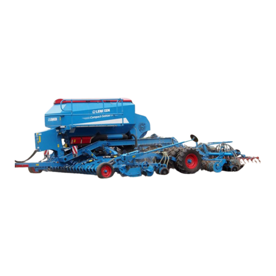
- Page 1 Compact-Solitair 9 HD - EN - Safety is our Concern! Part No.175_4360 LEMKEN GmbH & Co. KG Weseler Straße 5, D-46519 Alpen / Postfach 11 60, D-46515 Alpen Telefon (0 28 02) 81-0, Telefax (0 28 02) 81-220 E-Mail: lemken@lemken.com, Internet:...
- Page 3 Only use genuine LEMKEN spare-parts. Spurious parts negatively influence the function of the implement, show a shorter lifetime and increase in nearly all cases the maintenance effort. We trust that you will understand that LEMKEN is unable to guarantee poor op- eration and damage caused by using spurious parts!
- Page 4 Therefore use this instruction book with the ’General Health- and Safety precau- tions’! • The LEMKEN-implements have been designed purely for the agricultural use! Any use beyond the one stipulated above is no longer considered as defined use! •...
-
Page 5: Table Of Contents
Contents CONTENTS Definded Use........................2 Contents ........................... 3 Safety Instructions ....................8 Symbols used in the Operating Instructions............13 Hazard classes ......................13 Information........................13 Warning Stickers ..................... 14 General Instructions ....................14 Meaning of the Stickers ....................14 Position of Warning Stickers..................16 Other symbols ...................... - Page 6 Contents 6.10 Operation and adjustment of the hydraulic devices ..........26 6.10.1 Fan hydraulic ......................26 6.11 Implement hydraulics ....................27 Attaching and Detaching the implement .............. 28 Attaching........................28 Detaching........................30 Use..........................31 General Instructions ....................31 OptiDisc double disc coulters..................31 Impulse wheel......................
- Page 7 Contents 8.18 Agitator shafts ......................39 8.18.1 Agitator shaft in seed container ................39 8.18.2 Agitator shaft in fertiliser container ............... 39 Sequence control ....................40 General information ....................41 Raising the tools ......................42 Lowering the tools ...................... 42 Deactivating the raising and lowering process ............
- Page 8 Contents 10.13 Distributor ........................55 10.14 Electronic level monitoring ..................55 10.15 Harrow .......................... 55 10.15.1 S-harrow ....................... 56 10.15.2 Hydraulic lift ......................57 10.16 Pre-emergence markers ..................... 57 10.16.1 General Instructions ..................... 57 10.16.2 Pre-emergence marker – hydraulic, double acting ..........58 10.16.3 Pre-emergence marker –...
- Page 9 Contents 18.3 Cleaning the dosage units..................73 18.4 Cleaning the seed drill ....................74 18.5 Brake system ....................... 75 18.5.1 Drain valve......................75 18.5.2 Brake lining......................75 18.5.3 Cleaning filter......................75 18.5.4 Disconnecting the brake hoses................75 18.5.5 Re-adjusting the brake ..................76 18.6 Dust filter ........................
-
Page 10: Safety Instructions
Safety Instructions SAFETY INSTRUCTIONS General Safety Instructions • Before using the machine, always check both it and the tractor for roadworthi- ness and operational safety! • As well as the notes in these instructions the operator is advised to comply with the generally applicable safety at work regulations and those relating to use of the public highway! •... - Page 11 Safety Instructions • Fit and check transport gear, road lights and warning guards! • The release ropes for quick coupler latches should hang freely and in the low- ered position must not release the quick coupling by themselves. • Never leave the driver's seat whilst in motion! •...
- Page 12 • Regularly check the hydraulic pipes and replace them in the event of damage or signs of ageing. The replacement pipes must comply with the technical specification as laid down by Lemken! • When searching for leaks appropriate aids should be used because of the dan- ger of injury! •...
- Page 13 Safety Instructions Maintenance • Repair-, maintenance- and cleaning operations as well as adjustments and remedy of function faults should principally be conducted with engine stopped and brakes applied. Remove ignition key! • Check and tighten nuts and bolts regularly! • When conducting maintenance work on a lifted implement always place suit- able supports underneath! •...
- Page 14 Safety Instructions Brakes • Check function of brakes before each drive! • The braking systems must be checked regularly! • Repair work on brakes may only be conducted by trained staff and with suitable tools!
-
Page 15: Symbols Used In The Operating Instructions
Symbols used in the Operating Instructions SYMBOLS USED IN THE OPERATING INSTRUCTIONS Hazard classes The following symbols are used in the Operating Instructions for particularly im- portant information: DANGER Denotes an imminent hazard with high risk, which will result in death or severe physical injury, if not avoided. -
Page 16: Warning Stickers
WARNING STICKERS General Instructions The LEMKEN implement is equipped with all features to ensure safe operation. Where potential danger areas of the implement can not be fully safeguarded, warning stickers are fitted which draw attention to these. Damaged, lost or un- readable warning stickers must be replaced immediately. - Page 17 Warning Stickers WARNING: Keep well clear of the working and swinging area of the implement! 390 0510 WARNING: Pinch point! 390 0506 WARNING! Do not ride with on the platform of the implement!
-
Page 18: Position Of Warning Stickers
Warning Stickers Position of Warning Stickers... -
Page 19: Other Symbols
Other symbols OTHER SYMBOLS Lubricate and service implement in accor- dance with maintenance chart! Hydraulic hose connection overview P2 / T2: Raising Heliodor section, leading roller and seeding bar P3 / T3: Heliodor section working depth P5 / T5: Levelling work tines section P6 / T6: Blower... -
Page 20: Design And Description
Design and description DESIGN AND DESCRIPTION General information Front lighting system Tire packer / chassis and suspension Drawbar Leading roller Two-piece seed and fertiliser container Seeding rail Ascent Harrow Platform Advance marking Levelling work tines Rear lighting system Track markers Blower Heliodor compact disc harrow Spotlights... -
Page 21: Feeder Unit
Design and description Feeder unit 1 Feeder units for seed, left-hand fee- der units 2 Feeder units for fertiliser, right-hand feeder units 3 Bottom gate lever - left-hand feeder units 4 Bottom gate lever - right-hand feeder units 5 Shutoff valve - left-hand feeder units 6 Shutoff valve - right-hand feeder units 7 Feeder shaft for seed 8 Feeder shaft for fertiliser... -
Page 22: Container
Design and description Container The container (1) is divided by means of a partition wall (2) into a container (3) for the seed and a container (4) for the fertiliser. It has a capacity of almost 3500 l. The parti- tion wall (2) can be mounted in either a forward position or a rear position. - Page 23 Design and description The opening and closing of the tank cap (7) is supported by gas-filled telescopic struts (8) and a traction cable (9). If both containers are to be used for seed, the seed can be transferred from the rear fertiliser container into the front seed con- tainer.
-
Page 24: Preparation Of The Tractor
Preparation of the tractor PREPARATION OF THE TRACTOR Tyres Ensure that all are at the manufacturer's recommended pressures and that left and right hand side tyre pressures are identical. (See manufacturer's instructions)! Lift Rods Adjust lift rods to equal length by means of the adjuster device. (See tractor manu- facturer's instructions) Check Chains or Sway Blocks of the Three Point Linkage Check chains or sway blocks must be adjusted so that the lower links of the trac-... -
Page 25: Control
Preparation of the tractor Risk of injury through breakage of mounting studs WARNING A lower control link coupling with an undersize category may cau- se the mounting studs (2) to break! When tractors with a large output are used the mounting studs (2) may break! Control For operation and transport the tractor hydraulic is to be switched to “position con-... -
Page 26: Required Sockets
Preparation of the tractor Required sockets For the electric devices of the implement the following power sources must be available with the tractor. Direct connection Function Voltage Socket to the battery Electronic seed drill con- trol Lighting equipment according to DIN-ISO 1724 Working lights... -
Page 27: Required Hydraulic Control Units
Preparation of the tractor Required hydraulic control units For operation of the individual following listed hydraulic devices, the tractor must be equipped with the following control units. Hydraulic de- Single-acting control unit with Double-acting Colour Code vice depressurized return connection control unit Supply = yellow... -
Page 28: Hydraulic Brake System
Preparation of the tractor 6.9.2 Hydraulic brake system In combination with a hydraulic brake system the tractor must be equipped a hy- draulic coupling of the size BG 3. 6.10 Operation and adjustment of the hydraulic devices 6.10.1 Fan hydraulic Via the hydraulic pipes to the hydraulic motor of the fan also the valves for the hy- draulic switch of width sections, the hydraulic pre-emergence markers and the hy- draulic harrow lifting device will be pressurised with oil. -
Page 29: Implement Hydraulics
Preparation of the tractor 6.11 Implement hydraulics All other hydraulic functions on the implement are adjusted and actuated using either a double-acting control unit or two or three double-acting control units DW 1, DW 2 or DW 3 to match the equipment. In the basic equipment specification without a levelling work tines section and without any hydraulic working-depth ad- justment for the heliodor section, only one double-acting control unit DW 1 is re- quired for the complete sequence control, coulter pressure adjustment and the... -
Page 30: Attaching And Detaching The Implement
Attaching and Detaching the implement ATTACHING AND DETACHING THE IMPLEMENT Attaching − For attaching the hydraulics of the trac- tor must be set to position control! − Connect the tractor lower link (1) to the drawbar (2) and secure! − Swing stand (3) upwards and secure! −... - Page 31 Attaching and Detaching the implement − Adjust braking power regulator (7) in ac- cordance to the following table! − For the adjustment the lever (8) of the braking power regulator (7) will be turned correspondingly. That adjustment of the braking power is active to which the arrow (9) is pointing.
-
Page 32: Detaching
Attaching and Detaching the implement Detaching The implement must always be parked on level and firm ground! − Swing-down and secure stand (3)! − Set tractor hydraulics to position control before detaching the implement! − Remove the wheel chocks (4) out of the holders (5) and secure! −... -
Page 33: Use
General Instructions Before the first use it is recommendable - with fully lowered implement - to carry out the following adjustments at the farm. Afterwards only few adjustment correc- tions have to be carried out in the field. • With each hydraulic operation of the coulter bar and when lifting respectively lowering the Heliodor-section, the track markers will also be folded-in and –out at the same time. -
Page 34: Impulse Wheel
Sensors The function of the sensors has to be checked. See operating instructions for the LEMKEN Solitronic electronic seed drill control system. Tramline width Set tramline width to track width of cultivation tractor If the track width of the culti- vation tractor was quoted when the implement was ordered, the tramline width will be configured ex-factory. -
Page 35: Blower Speed
8.10 Blower speed The blower speed has to be set to the required speed using the tractor's flow con- trol valve. See section on "Blowers". 8.11 Solitronic electronic seed drill control system The electronic seed drill control system enables the implement to be configured using the control terminal (12) whereupon the calibration test sample can then be conducted. -
Page 36: Feeder Shaft For Fertiliser
8.12.2 Feeder shaft for fertiliser The feeder shaft (6) is equipped with four feeder wheels (7) for each feeder unit (8), they are separated from each other by par- ting discs. The feeder wheels (7) for fertilisers may not be switched off. 8.13 Switching seed wheels on or off The seed wheels (1) are switched on or off... -
Page 37: Switching On The Seed Wheels
8.13.1 Switching on the seed wheels A seed wheel is switched on by screwing in the stop screw (2). When screwing in the stop screw, care must be taken to ensure that it is always screwed exactly into the groove (5) of the feeder shaft (4), and therefore always within the seed wheel circumference. -
Page 38: Switching Off The Seed Wheels
8.13.2 Switching off the seed wheels The seed wheels (1) are switched off by undoing the stop screw (2), and by doing so far enough until it makes contact with the stop plate (6). The stop screw must not be unscrewed too far out of the tooth root (7), as it may then drop out. -
Page 39: Bottom Gate Position
LEMKEN Solitronic electronic seed drill control system. -
Page 40: Filling
8.17 Filling To fill the container the lid (1) must be swi- velled upwards. To do so grab the handles (2) and swivel the lid (1) upwards against the force of the gas-filled telescopic strut (3). Use the trac- tion cable (4) to make sure that the lid (1) can be swivelled in a controlled manner into its end position. -
Page 41: Agitator Shafts
8.18 Agitator shafts 8.18.1 Agitator shaft in seed container For example, for encrusted rape, the agita- tor shaft (1) has to be switched off. This is done by pulling the split ring (3) out of the drive pinion (2) of the agitator shaft (1). 8.18.2 Agitator shaft in fertiliser container The agitator shaft (4) in the fertiliser con- tainer should not be switched off. -
Page 42: Sequence Control
Sequence control SEQUENCE CONTROL • Activate the sequence control only when no-one is standing in WARNING the vicinity of the implement's operating or swivelling range! • The actions induced by activating the sequence control are conducted as long as the control unit DW1 is kept in the pres- sure position or until the respective operating position is reached. -
Page 43: General Information
Sequence control General information When the control unit DW 1 is actuated for raising and lowering the heliodor section (compact disc harrow), the sequence con- trol is activated. The following occurs when the lever of the control unit DW1 is kept in the pressure position −... -
Page 44: Raising The Tools
Sequence control At the same time the sowing shaft and the feeder shaft for the fertiliser are stop- ped. If necessary, the sensor (1) can be adjusted in height, which in turn results in the sowing shaft and the fertiliser feeder shaft having an earlier or later start or stop. -
Page 45: Adjustments
Adjustments ADJUSTMENTS • Read and adhere to the General Safety Instructions! • The implement may only be operated, maintained and repaired by such persons who have been made acquainted with it and who have been advised about the dangers! • Adjustment- maintenance operations... -
Page 46: Drilling Depth Of The Seeding Coulters
Adjustments 10.1.2 Drilling Depth of the seeding coulters With the adjuster screw (1) the drilling depth is adjusted. Turn the screw clockwise => deeper drilling depth. Turn the screw anti-clockwise => less deep drilling depth 10.1.3 Settling depth of fertiliser coulter Set settling depth using guide pin (1)! For large settling depths, insert the guide pin (1) into a hole in the upper row of holes... -
Page 47: Coulter Pressure For Seeding Coulter
Adjustments 10.1.4 Coulter pressure for seeding coulter The hydraulic coulter pressure system oil supply is provided by the blower hydraulics. Coulter pressure can only be generated and changed, when the blower is running. The right pressure reducing valve (1) can be used to set the coulter pressure for the seeding coulter (4). - Page 48 Supplementary information SUPPLEMENTARY INFORMATION Fertiliser coulters The working depth of the fertiliser coulters must be shallower than the working depth of the soil working implement operating ahead of them. 1.1.1 Replacing the scraper The double disc coulter is fitted with a self- adjusting hard metal scraper.
- Page 49 Supplementary information 1.1.2 Setting the coulter pressure The coulter pressure can be increased or reduced by increasing or reducing the ten- sion of the compression spring (1). Compression spring tension Compression spring Coulter pressure [kg] length [mm] [mm] Max. 97 Increasing the coulter pressure reduces the trip height of the coul- ter.
- Page 50 Supplementary information Increasing the coulter pressure To increase the coulter pressure, tighten the compression spring (1): Turn the nuts (2)+(3) on the threaded rod (4) towards the compression spring (1). Tighten the lock nut (3) to hold them in position.
-
Page 51: Harrow
Adjustments 10.2 Harrow The harrow (1) should flatten the ground. It has a free-swivelling connection to the seeding bar, enable it to easily adjust to the contours of the ground. It is limited in depth by a stopper. 10.2.1 Angular position The angular position of the harrow tines (2) can be adjusted using the spindle (3). -
Page 52: Operation And Adjustment Of The Track Markers
Adjustments If the track markers (1) or the Heliodor section (2) or seeding rail (3) or fertiliser bar are to be actuated for maintenance or adjusting work, the functions are all conducted at the same time in activated condition. When control unit DW1 is actuated, the track markers are folded DANGER and the heliodor section, and the seeding rail are raised or low- ered! Ensure a sufficient safety distance is given! No-one is to... - Page 53 Adjustments arms (7) and the angle of the track marker discs (8) can be adjusted. After the ad- justment the corresponding clamp screw (6) must be tightened again. Pin (5) in locking position Distance from the centre of the Distance to the outer seed Working width of the im- plement seed drill to the track groove...
-
Page 54: Working Depth Of The Heliodor-Section
Adjustments 10.4 Working depth of the Heliodor-section The working depth of the hollow discs (1) will be adjusted by means of a turnbuckle or a hydraulic ram (2). Range of working depth = 3 cm to 10 cm. The left rear hollow disc (3) can be ad- justed stepless in working depth via slotted holes (4). -
Page 55: Lateral Draw
Adjustments 10.5 Lateral draw The front and the rear inclined hollow discs exert counteracting lateral forces which counterbalance each other. Lateral forces which should occur can be elimi- nated as follows: Lateral draw to the right => lift tractor hydraulic slightly Lateral draw to the left =>... -
Page 56: Levelling Tine Section
Adjustments 10.7 Levelling tine section Via the hydraulic ram (1) the levelling an- gle (2) can be adjusted as desired. Open hydraulic ram (1) = shallower level- ling angle Close hydraulic ram (1) = steeper levelling angle When worn the levelling shares (3) can be displaced at the tine. -
Page 57: Tramline Mechanism
Via the entering menu of the electronic seed drill control LEMKEN Solitronic the working width of the following implement will be entered. The required tramline rhythm will be calculated automatically. -
Page 58: Fan
Adjustments • When the pulse wheel will be turned, the seed wheels, the seed- ing shaft and the agitator shaft turn also! Keep distance! 10.10 Fan A constant oil supply is required (approx. 35 l/min) in order to ensure a constant fan RPM. -
Page 59: Blower For Fertiliser Spreading
Adjustments 10.11 Blower for fertiliser spreading If fertiliser is to be spread in parallel to seed, then the speed of the blower has to be increased. For larger quantities of fertiliser, the blower speed must be in- creased to approx. 4000 – 4100 rpm. 10.12 Switch of width sections Depending on the working width of the seed drill, dosage units can be switched off... -
Page 60: Distributor
Adjustments 10.13 Distributor The distributors (1) are provided with dis- tributor heads (2) with thread, which en- able a simple check of the distributor. If required, some exits of the distributor can be closed by means of plugs. Therefore the distributor heads (2) must be removed and the plugs put in those exits which should be closed. -
Page 61: S-Harrow
Adjustments 10.15.1 S-harrow The S-harrow will be screwed to the carrier (1) respectively the coulter bar. The harrow position will be adjusted by means of the pins (2) and (3). The harrow tines (4) should be set a little bit deeper at the rear than in front during work. -
Page 62: Hydraulic Lift
Adjustments IMPORTANT! It must always be ensured that the pulse wheel (9) never touches the harrow during work Before each transport, the S-harrows must be folded-in and se- cured, in order to prevent injury. Worn harrow tines, which show sharp points pointing rearwards, only, must be covered by a trans- port safety device. -
Page 63: Pre-Emergence Marker - Hydraulic, Double Acting
Adjustments 10.16.2 Pre-emergence marker – hydraulic, double acting The carriers (1) of the hollow discs (2) will be fitted to the wheel stalk of the depth control wheels. The hollow discs will be lowered by means of the hydraulic rams (3), when a tramline should be made. -
Page 64: Pre-Emergence Marker - Hydraulic, Single Acting
Adjustments 10.16.3 Pre-emergence marker – hydraulic, single acting The hollow discs (1) can exactly be ad- justed to the track measurement of the fol- lowing tractor. Therefore the brackets of the units will be moved to the desired track measurement. Also after loosening the clamp screw (2), the hollow discs can be adjusted to the de- sired track measurement. -
Page 65: Depth Of The Marking Groove
Adjustments 10.16.4 Depth of the marking groove By means of turning the spring (4) the depth of the marking groove can be pre- adjusted. Turning the spring clockwise => deeper marking grooves Turning the spring anti-clockwise => shal- lower marking groove By means of the bolt (5) the brake discs (6) will be pressed against the spring, so that the position of the spring cannot change unintentionally, but still can be ad- justed manually. - Page 66 Adjustments This ground pressure adjustment version is superseded by a version, in which the control terminal of the Solitronic electronic seed drill control system can be used to gradually adjust the ground pressure. See operating instructions for Solitronic electronic seed drill control system as of version 1.51.
-
Page 67: Seedtable
Seedtable SEEDTABLE... -
Page 68: Emptying The Seed Container
Emptying the seed container EMPTYING THE SEED CONTAINER The seed container can be emptied easily; small residual quantities are emptied into the calibration tray (1), larger residual quantities can be emptied through the spreaders. 12.1 Emptying in the calibration tray The seed container and the fertiliser con- tainer can be emptied by simply swivelling the drainage gates (1) and opening the... -
Page 69: Emptying With The Spreaders
Emptying the seed container 12.2 Emptying with the spreaders After unscrewing the spreader heads (1) a connecting sleeve (3) with hose (4) can be screwed onto a spreader (2), which then enables the seed container to be emptied pneumatically using a blower. The seed container or fertiliser container can be emptied either through one or two spread- ers as follows. -
Page 70: Tyres
Tyres TYRES The minimum and maximum allowed operation pressure of the tyres can be found in the following table: IMPORTANT! The air pressure must be checked regularly! min. allowed air max. allowed air Description Profile pressure (bar) pressure (bar) 420/65 R 20 XM 108 405/70-20 AS 504... -
Page 71: Working Spot Lights
Working spot lights WORKING SPOT LIGHTS The working spot lights (1) will be switched on and off in the entering menu via the op- eration terminal of the electronic seed drill control. See also operation instructions of the elec- tronic seed drill control Solitronic. -
Page 72: Tips For Driving On Public Roads
Tips for driving on public roads TIPS FOR DRIVING ON PUBLIC ROADS 15.1 General information A proper lighting system, identification and equipment must be on the implement, if it is to be transported on public roads. The country-specific valid laws and regu- lations pertaining to driving on public roads must be observed. -
Page 73: Folding-In And -Out The Outer Hollow Discs
Folding-in and –out the outer hollow discs FOLDING-IN AND –OUT THE OUTER HOLLOW DISCS 16.1 Folding-in the outer hollow discs For transport the outer hollow discs (1) must be folded-in as follows: − Release the locking pin (2) and detach. −... -
Page 74: Folding-Out The Outer Hollow Discs
Folding-in and –out the outer hollow discs 16.2 Folding-out the outer hollow discs For work the outer hollow discs (1) must be folded-out as follows: − Release locking pin (2) and remove it out of hole (3). − Now the outer hollow disc concerned can be folded-out. -
Page 75: Technical Data
Technical data TECHNICAL DATA Compact-Solitair HD 9/300 9/400 Number of seeding coulters with 167 mm row spac- Number of fertiliser coulters with 334 mm row spac- Seed container / fertiliser container 2,100 l / 1,400 l 2,100 l / 1,400 l Weight approx. -
Page 76: Maintenance
Maintenance MAINTENANCE 18.1 Lubrication chart All lubricating points must be greased in accordance with the lubrication chart: Lubrication chart Every 50 Every 100 Before a After a service service winter winter hours hours break break a) Hydraulic cylinder for raising Heliodor section (2x) b) Hydraulic cylinder for Heliodor section working depth (2x) - Page 77 Maintenance...
-
Page 78: Bolts
Maintenance 18.2 Bolts All nuts and bolts must be tightened after the first few hours of use, at least within the first 8 hours and checked, and tightened if necessary. At least every 50 hours all bolts and nuts must be checked for tight fit and tightened if necessary and se- cured with Loctite. -
Page 79: Cleaning The Seed Drill
Maintenance slide plates, fit protection covers and finally fit calibration tray. When removing the calibration tray the emptying flaps will be closed automatically. The closing of the emptying flaps is clearly audible. 18.4 Cleaning the seed drill The seed drill must always be cleaned with compressed air after each operation, in particular, after spreading fertiliser. -
Page 80: Brake System
Maintenance 18.5 Brake system 18.5.1 Drain valve Operate drain valve (1) regularly, in order to drain the air tank (2). 18.5.2 Brake lining Worn brake linings must be replaced. 18.5.3 Cleaning filter The cleaning filters (3) must be cleaned every 50 working hours. Therefore the se- curing bar (4) must be removed. -
Page 81: Re-Adjusting The Brake
Maintenance 18.5.5 Re-adjusting the brake The brake cylinder (5) shows a stroke of 80 mm. When with a braking the brake levers (6) open more than 60 mm after a long time of use, the brake must be re- adjusted. Therefore use the adjuster nuts (7). -
Page 82: Wheel Bolts
18.10 Disc coulters and pressure rollers Worn disc coulters and scrapers must be replaced in time, so that the carrying parts will not be damaged. Use only genuine LEMKEN spare parts! 18.11 Seed wheels and bottom flaps Before the winter break or before longer parking times, the seed drill must be emptied, cleaned and the bottom flaps completely opened, to avoid damage by mice. -
Page 83: Cleaning With Pressure Washer
Maintenance 18.12 Cleaning with pressure washer When cleaning the implement with a pressure washer, it must be ensured that no water runs into the electronic parts. Also it must be avoided that the nozzle is di- rected on to the pivot points of the coulter bar, the bearings of the coulters and rollers. -
Page 84: Noise, Airborne Sound
Noise, Airborne Sound NOISE, AIRBORNE SOUND The noise level of the implement does not exceed 90 dB (A) during work. DISPOSAL After useful life of the implement, it must be disposed of environment-friendly by a specialist. NOTES As the version of equipment is depending from the order, the equipment of your implement and its description concerned may deviate in some cases. -
Page 85: Index
INDEX Agitator shafts ..................... 39 Bottom gates ....................... 37 Brake system ...................... 25 Braking system....................67 Calibration test sample..................37 Check Chains...................... 22 Cleaning......................74 Cleaning the dosage units................... 73 Container ......................20 Deactivating ......................42 distributor ......................55 double disc coulters..................... 43 Drilling Depth of the seeding coulters .............. - Page 86 Index Levelling tine section ................... 51 Lowering ......................42 Lubrication chart....................71 Operation terminal....................67 preparation of the tractor ..................22 Pulse wheel......................52 Raising ........................ 42 Required hydraulic control units ................25 scrapers ......................43 Seed wheels......................34 Sequence control ....................40 Settling depth of fertiliser coulter .................
Need help?
Do you have a question about the Compact-Solitair 9 HD and is the answer not in the manual?
Questions and answers