
Related Manuals for LEMKEN JUWEL 8 I


Summary of Contents for LEMKEN JUWEL 8 I
- Page 1 OPERATING INSTRUCTIONS MOUNTED REVERSIBLE PLOUGH JUWEL 8 I en-GB | Item no. 17515128 | BA 00/08.2021...
- Page 2 Pass these instructions to all users / owners. Original instructions © 2021 | This documentation is copyright protected. The copyright remains with LEMKEN GmbH & Co. KG, Weseler Strasse 5, D-46519 Alpen. The texts, diagrams and drawings must not be duplicated, distributed or disclosed in any other way,...
-
Page 3: Table Of Contents
Table of contents Table of contents About these instructions............................1 1.1 Introduction................................. 1 1.2 Target groups..............................2 1.3 Applied symbols..............................2 1.3.1 Design of warning signs..........................2 1.3.2 Signal words and hazard statements...................... 3 1.3.3 Warning of property damage........................3 1.3.4 Other notices and information........................ - Page 4 Table of contents 3.14 Operation terminal............................25 Attaching..................................26 4.1 Checking suitability of the tractor......................26 4.2 Preparations at the tractor........................... 27 4.3 Mounting the machine..........................28 Road travel................................. 31 5.1 Information on road travel........................... 31 5.2 Preparing for road travel..........................31 5.2.1 Preparing the lighting equipment for road travel................
- Page 5 Table of contents 6.4.1 Standard procedure............................ 65 6.4.2 Driving on the headland........................... 66 Cleaning and care..............................67 7.1 After working in the field..........................67 7.2 Cleaning with high-pressure cleaner....................... 67 Detaching................................... 68 8.1 Detaching the machine..........................68 Maintenance and repair work.......................... 70 9.1 Maintaining the machine properly......................
- Page 6 Table of contents 12.6 Connection data............................87 12.6.1 Electrical connections..........................87 12.6.2 Hydraulic connections..........................88 12.7 Noise, airborne sound..........................88 12.8 Operating materials............................. 88 12.9 Tyres and wheels............................89 12.10 Permitted shear bolts..........................89 12.11 Connecting systems at the machine....................90 Index.....................................
-
Page 7: About These Instructions
About these instructions About these instructions Introduction Observe the operating instructions These operating instructions are important and belong to the machine's scope of delivery. These operating instructions must be available to the user at the place of use. Always read chapter "Safety" before using the machine for the first time. -
Page 8: Target Groups
About these instructions Initial commissioning These operating instructions do not describe initial commissioning. INFORMATION Prior to operation, initial commissioning and instruction in operation, setting and maintenance must have been carried out by the dealer. Target groups The target groups of these operating instructions are operators, users and service personnel of the machine. -
Page 9: Signal Words And Hazard Statements
About these instructions 1.3.2 Signal words and hazard statements The following signal words and hazard statements are used to label warning signs and to warn of residual risks: DANGER Indicates an immediate hazardous situation If the hazardous situation is not avoided, it will result in death or serious injury. -
Page 10: Symbols And Text Markings
About these instructions 1.3.5 Symbols and text markings Symbol, text marking Meaning In front of and in texts Marking for routine maintenance ● tasks Activities that demand the help of service staff. Listing Position numbers [1], Example: ‘Settings’ Software element Example: [OK] Softkey, key, switch and button [kg]... -
Page 11: Further Applicable Documents
About these instructions Further applicable documents Further documents to be observed: Operating instructions of the tractor For partially assembled or disassembled delivery: Mounting instructions Spare parts list Operating instructions for the furrow press Operating instructions, operation of the control Operating instructions for the operation terminal INFORMATION In other documents and in sections of these operating instructions, the machine is also referred to as an imple‐... -
Page 12: Safety
Safety Safety Intended use The machine is used for soil cultivation on agricultural land. It may only be used in accordance with the recognised rules of good agricultural practice. Limitations The permitted working depth is limited to the cultivatable soil horizons. Not intended for use in the following cases: On very or deep-frozen soils In soil horizons with unweathered bedrock... - Page 13 Safety Operating instructions The operating instructions are part of the machine. The machine is intended exclusively for use in accordance with these operating instructions. Applications of the machine not described in these oper‐ ating instructions may result in personal injury or death or property damage.
-
Page 14: Personnel Qualification Requirements
Safety Personnel qualification requirements Operator The operator is obliged to inform all the users about correct application of the machine and the respective hazards. This can be done on the basis of these operating instructions. The operator is responsible for ensuring that the operating instructions are always available at the machine and that the users observe the operating instructions. - Page 15 Safety Moving hazardous area The hazardous area of the machine during operation. Moving hazardous area The hazardous area includes the area in the direction of travel across the entire width of the machine. NEVER climb out of the tractor while it is moving. ►...
-
Page 16: Workplaces And Passengers
Safety Parked machine The parked machine may overturn. This may result in fatal or serious injuries. Park the machine in operating position. ► Park the machine on firm and level ground only. ► Place a plate (metal, wood, stone) with sufficient carrying capacity ►... -
Page 17: Technically Perfect Condition
Safety Observe the hazardous areas. ► Pay attention to other persons in the vicinity of the machine. ► Passengers Passengers may fall from the machine and seriously injure themselves. Scattered objects may hit and injure passengers. NEVER allow persons to ride along on the machine. ►... - Page 18 Safety Danger due to damage to the Damage to the machine can impair the operational safety of the machine machine and cause accidents. This may result in fatal or serious injuries. To ensure that the machine is in a safe condition, carry out the fol‐ lowing measures: Check the machine according to the maintenance schedule.
-
Page 19: Safe Handling
Safety Safe handling 2.6.1 Personal protective equipment Carrying and wearing protective equipment is an important safety component. Lack of or inappropriate protective equipment increases the risk of damage to health and injury to persons. For certain work on the machine, the following protective equipment is required in addition to suitable workwear: Safety gloves Use protective equipment as follows:... -
Page 20: Safety Devices And Labels
Safety Safety devices and labels For the protection of the user, other persons and the machine, the machine is equipped with special safety devices, e.g.: Lighting equipment and markings Stabilisation The actual equipment of the machine with safety devices depends on the country-specific rules and regulations. -
Page 21: Design And Description
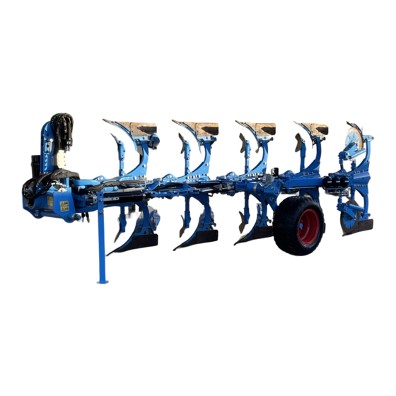
Design and description Design and description Machine overview INFORMATION Depending on the equipment of the machine and country-specific requirements, the assembly groups described below may be present on the machine. Cross shaft Additional tools (skimmer, trashboard) Turnover device Disc coulter Headstock Depth wheel Job computer... -
Page 22: Machine Safety
Design and description Machine safety 3.2.1 Position of the label Juwel 8 i - Overview of safety symbols, warning stickers and other symbols 3.2.2 Meaning of the labels This section explains the information and warning signs that have been affixed to the machine. -
Page 23: Safety Devices
Design and description Turn off the engine A tractor with the engine running can cause unintentional movements. This may even be fatal or result in serious injuries. Before maintenance and repair work: Turn off the engine. ► Engage the parking brake of the tractor. ►... - Page 24 Design and description Lighting equipment Lighting equipment example Warning boards Lateral reflectors LED lighting equipment Rear reflectors Warning board Depending on national regulations, a warning board may be required for slow-moving vehicles. 3.2.3.2 Stabilisation Stand The stand ensures that the dismantled machine is stable. When mounted, the stand is folded up again.
-
Page 25: Type Plate
Design and description 3.2.3.3 Depth and transport wheel pins Pins for securing the depth and transport wheel Type plate The machine is marked with a type plate. The machine type is uniquely defined on the type plate. Sample design of a type plate (standard) Series Type designation Model year... -
Page 26: Headstock
Design and description Ä Further type plate versions: Type plate variants on page 96. Headstock Headstock The headstock with cross shaft and top link pin has been Top link pin designed according to standard ISO 730. Cross shaft The headstock is used to connect the implement to the three-point linkage of the tractor. -
Page 27: Optiquick Adjustment Centre
Design and description Double-cutting shearing protection Shear bolt Double-cutting shearing protection in the leg brackets is standard on all machines. Shear bolts are replaced when broken. Hydraulic overload safety device OptiStone Hydraulic overload safety device With the hydraulic overload safety device the release force is adjusted between a minimum and a maximum release pressure. -
Page 28: Onland Version
Design and description Variant with hydraulic adjustment of the draw point and the front Hydraulic ram – frame swing-in and draw point adjustment furrow width and hydraulic frame swing-in Inner hydraulic ram (front furrow width) The draw point , the front furrow width and the hydraulic frame swing-in are adjusted using the control MegaPlough. -
Page 29: Additional Tools
Design and description Dural Mouldboard blade The following belongs to the plough body: Shin Mouldboard, divided into shin and mouldboard blade or slat Shin Share wing Share wing Share, divided into share wing and point Point Frog Point Landside Slat Frog Landside 3.11... -
Page 30: Disc Coulter
Design and description Sword coulter 3.12 Disc coulter The large disc coulters pre-cut the furrow edge. Various disc coulters are available. Disc coulter, smooth Equipment with disc coulter smooth, stalk rigid Stalk, rigid Disc coulter, smooth Equipment with disc coulter smooth, stalk rigid, adjustable Stalk rigid, adjustable lengthwise... -
Page 31: Subsoiler
Subsoiler Example: Subsoiler 3.14 Operation terminal LEMKEN ISOBUS operation terminal The machine control is operated via an ISOBUS operation terminal, e.g. LEMKEN CCI 1200. An ISOBUS operation terminal can also be combined with additional (AUX) input devices for the ISOBUS. -
Page 32: Attaching
Attaching Attaching Checking suitability of the tractor WARNING Risk of accident due to unsuitable tractor If the tractor is not suitable for the machine, compo‐ nents of the machine may be overloaded and the tractor- machine combination may not be steered safely. This may result in accidents with injuries or death of persons or damage to the machine. -
Page 33: Preparations At The Tractor
Attaching Preparations at the tractor Keep the tractor documentation The tractor is prepared before attaching the machine. For this purpose, ready the user must carry out various checks and adjustments. The following information about the tractor is required: Air pressure of tyres Instructions for adjusting the lifting rods Instructions for adjusting the check chains or stabilisers Tasks on the tractor... -
Page 34: Mounting The Machine
Attaching Checklist At tractors with several attachment positions for the top Top link link: Check attachment position of the top link. Attach the top link, ensuring the top link in the extension points towards the front axle of the tractor. Mounting the machine WARNING Risk of accident due to unsuitable tractor... - Page 35 Attaching 1. Switch the hydraulics of the three-point linkage to position control for attachment. 2. Move the tractor straight back in front of the machine. Stop at a distance of about 40 cm. The lower links are positioned in front of the cross shaft 3.
- Page 36 Attaching 18. Select attachment position for the top link. Slot Fixed hole Quick penetration on the Even field areas headland For tractors with top link Better ground adaptation control on hilly terrain For ploughs with mechan‐ Pin in the centre of the ical and hydraulic over‐...
-
Page 37: Road Travel
Road travel Road travel Information on road travel Laws on driving on public roads differ in many countries. Pay particular attention to local laws and regulations regarding the ► following points: Driving on public highways Maximum permissible transport height Maximum permissible transport width Maximum permissible transport weight Lighting equipment Markings... -
Page 38: Preparing The Lighting Equipment For Road Travel
Road travel Checklist Lighting equipment The lighting equipment must be mounted and fully functional. Ä See page 32 Subsoilers Subsoilers must be remounted to transport position. Ä See page 33 Control units of the tractor Observe the instructions of the tractor manufacturer. To avoid unintentional movements of the machine: Lock the tractor control units. -
Page 39: Subsoilers
Road travel Connecting the electrical line 1. Connect the electrical line of the lighting equipment. Connect the connector of the lighting equipment to the socket 2. Test the lighting equipment. Lighting equipment 5.2.2 Subsoilers Socket Before driving on the road: Move the subsoilers to the transport posi‐ tion. -
Page 40: Operation
Operation Operation Basic operation 6.1.1 Turning the plough frame Turnover ram The turnover device is equipped with a double acting turnover ram Hydraulic ram for frame swing-in with switching. Machines with hydraulic frame swing-in are additionally equipped with a double acting hydraulic ram Operation of the hydraulic functions takes place using the control Meg‐... - Page 41 Operation Switching depth and transport wheel CAUTION Risk of crushing Crushing and shearing points in the area of the wheel stops – Do NOT reach into the crushing points and shearing points. Hydraulically adjustable depth and transport wheel 1. Turn the plough to the right operating position. 2.
- Page 42 Operation Hydraulically dampened depth and transport wheel 1. Rotate the plough to the right-turning position. 2. Park plough on the ground. 3. Remove the pin 4. Disconnect the hydraulic damper from the wheel stalk CAUTION: Crush risk 5. Lift up plough. Hydraulic damper 6.
-
Page 43: Moving The Plough With Depth And Transport Wheel To Operating Position
Operation 3. Pull up the detent pin ð The lever swivels back into position . ð The locking pin extends. Detent pin 4. Turn the plough to the transport position using the control Mega‐ Lever Plough. See operating instructions for the control. Locking pin 5. - Page 44 Operation Hydraulically adjustable depth and transport wheel 1. Turn the plough to the right operating position. 2. Release and pull out the pin 3. Swivel depth and transport wheel by 90° towards the plough frame. 4. Fix the depth and transport wheel in this position with the pin 5.
-
Page 45: Operating The On-Land Version
Operation 7. Mount the hydraulic damper on the wheel stalk 8. Secure the hydraulic damper with the pin 9. Lift up plough. Hydraulic damper Wheel stalk Moving the plough to operating posi‐ tion 1. At the Optiquick adjustment centre, close the ball valve of the outer hydraulic ram until the ball valve engages. - Page 46 Operation When switching the operating status of the machine to O-operation, Switching from F-operation to O- the following options are available to the user: operation Softkey ‘O-operation’ Softkey ‘Increase front furrow’ The procedure with the softkey ‘O-operation’ is described below. Precondition: √...
-
Page 47: Changing The Setup State
Operation Precondition: √ The machine has a front furrow value less than 15% and is thus in O-operation. 1. Press the softkey ‘F-operation’ once. ð The machine returns to the last adjustment in F-operation. ð The machine has a front furrow value greater than 15% and is thus in F-operation. -
Page 48: Mounting The Wide Furrow Cutter
Operation 2. Remove the landside wedge 3. Mount the sword coulter with two countersunk screws in front of the landside. 4. Tighten the countersunk screws 6.2.3 Mounting the wide furrow cutter Wide furrow cutter The wide furrow cutter widens the furrow of the last plough body. √... -
Page 49: Adjusting The Machine
Operation Adjusting the machine 6.3.1 All adjustments at a glance The following table shows the adjustments that the user can make at the machine. Preconditions: √ The machine has been attached properly to the tractor. √ The top link is adjusted correctly. Ä... -
Page 50: Adjusting The Working Width Of The Plough Bodies
Operation Adjustment options at the machine Adjustment Tractor/plough traction line (side pull correction) - standard version Ä Adjusting the tractor/plough traction line, page 50 Tractor/plough traction line (side pull correction) - on-land version Ä Adjusting the tractor/plough traction line - on-land version, page 51 Pitch angle Ä... -
Page 51: Adjusting The Depth
Operation The working width of the plough bodies is adjusted via the tractor. The MegaPlough hydraulic ram for adjusting the working width is controlled using an additional control unit or the control. Preconditions: √ The front furrow width is adjusted. √... - Page 52 Operation Standard procedure 1. Switch the hydraulics for the rear lifting gear of the tractor to draft control or mixed control. 2. Preset the position of the touch wheel, to do so: Lower the machine to the ground. Adjust the position of the touch wheel. ð...
-
Page 53: Adjusting The Inclination
Operation If a finer adjustment is required, the stop can be moved to a different position. 1. Turn over the stop 2. Secure the pin with the linch pin Adjusting the working depth - depth and transport wheel, hydraulically adjustable Adjust the working depth using the control MegaPlough. -
Page 54: Adjusting Front Furrow Width
Operation Adjusting the inclination using the The inclination is adjusted using the control MegaPlough. See oper‐ control ating instructions for the control. 1. Adjust the inclination using the control. Softkey Adjustment Increase the inclination angle. Reduce the inclination angle. 2. Check the inclination. 3. -
Page 55: Adjusting The Front Furrow Width - On-Land Version
Operation 6.3.6 Adjusting the front furrow width - on-land version: Precondition: The inclination of the plough is adjusted correctly on both sides. F-operation The front furrow width is adjusted using the inner hydraulic ram of the Optiquick adjustment centre. Here, the front furrow width is adapted to the working width of the other plough bodies. -
Page 56: Adjusting The Distance Between The Tractor And The Furrow Edge - On-Land Version
Operation 6.3.7 Adjusting the distance between the tractor and the furrow edge - on-land version The distance between the tractor and furrow edge determines the front furrow width. Adjustment takes place with the inner hydraulic Precondition: √ The machine is in O-operation. √... -
Page 57: Adjusting The Tractor/Plough Traction Line - On-Land Version
Operation Checking the side pull: ► Side pull Tractor pulls towards Turn the inner turnbuckle 1 the ploughed land. longer. Tractor pulls towards Turn the inner turnbuckle 1 the unploughed land. shorter. 6.3.9 Adjusting the tractor/plough traction line - on-land version F-operation (left) and O-operation (right) Preconditions: The machine is in O-operation. - Page 58 Operation ► Adjust the tractor/plough traction line with the hydraulic ram Side pull Tractor pulls towards Press the softkey. the ploughed land. The hydraulic ram extends. Tractor pulls towards Press the softkey. Hydraulic ram – frame swing-in and the unploughed land. The hydraulic ram retracts.
-
Page 59: Adjusting The Pitch Angle Of The Plough Bodies
Operation 6.3.10 Adjusting the pitch angle of the plough bodies DuraMaxx The pitch angle is adjusted via the position of the eccentric plate When delivered, the plough bodies are mounted at an average pitch angle to the ground. The eccentric plate is in the middle position. The notch of the eccentric plate points to the front. - Page 60 Operation Dural Standard procedure: INFORMATION Adjust all the plough bodies to the same pitch angle. – Bear from behind over the rearmost and foremost point. – Adapt individual plough bodies to this height. 1. Adjust pitch angle of the first and last plough body. 2.
-
Page 61: Adjusting The Landside Of Duramaxx Plough Bodies
Operation 4. Adjust the pitch angle. Target Pitch Adjustment angle Improved Larger Screw in the adjusting screw penetration pitch clockwise. Unscrew the angle adjusting screw anti-clock‐ wise. Improved Smaller Screw in the adjusting screw depth con‐ pitch clockwise. Unscrew the Larger pitch angle trol angle... -
Page 62: Adjusting The Working Depth Of The Subsoilers
Operation Move the landside INFORMATION Set the landsides on all the plough bodies to the same position. 1. Undo the screw 2. Remove the screw 3. Set the landside to another position. 4. Reinsert the screws 5. Tighten the screws Ä... - Page 63 Operation DuraMaxx equipment Trashboard 1. Align the trashboard using the slots on the holder Holder 2. Screw the trashboard to the holder. 3. Align the holder using the slots on the leg Slots 4. Screw the holder to the leg. Slots Slots Slots...
-
Page 64: Adjusting The Skimmer
Operation Support screw Lock nut 6.3.14 Adjusting the skimmer The skimmer has the following setup options: Working depth Stalk position Projection angle Working depth Target: Distance The required working depth of the skimmer is approx. 5 to 10 cm. – For a plough working depth of 25 cm, this results in a distance (skimmer point to plough body point) of approx. - Page 65 Operation 6. Secure the pin with linch pin Stalk position To optimise the position of the skimmer for the respective operating conditions: Change the stalk position. 1. Undo the bolted connections 2. Move the stalk to the required position. Changing the stalk Effects position More free space between the...
-
Page 66: Adjusting The Disc Coulter
Operation Projection angle: 1. Release and pull out the pin 2. Swivel the skimmer to the required position. 3. Swivel the lug Align the holes in the lug and the swivelling bracket Skimmers 4. Connect the lug and the swivelling bracket with the pin Stalk Swivelling bracket 5. - Page 67 Operation DANGER Stored mechanical energy Spring-loaded disc coulters are preloaded. Uncontrolled release of mechanical energy accelerates components like a projectile. After each adjustment: – Retighten the loosened bolted connections. – Check whether the disc coulters can oscillate freely when viewed in the direction of travel. –...
- Page 68 Operation Spring-loaded disc coulter: 1. Undo the screw . 2. Swivel the coulter arm to the required working depth. Ensure that the gearing of the coulter arm and the adjacent Hirth-type bracket mesh exactly. 3. Retighten the screw . Coulter arm Screw Toothed bracket Side distance...
- Page 69 Operation The side distance to the landside of the plough body is adjusted by swivelling the coulter stalk 1. Undo the screw 2. Swivel the coulter stalk in the slot until the required position of the coulter disc has been reached. 3.
- Page 70 Operation Disc coulter next to skimmer equipment 1. Swivel the disc coulter towards the skimmer 2. Limit the swivel area with the adjusting piece up to this point. Disc coulter Disc coulter in front of skimmer equipment Adjusting piece Skimmers ►...
-
Page 71: Adjusting The Release Force Of The Hydraulic Overload Safety Device
Operation 6.3.16 Adjusting the release force of the hydraulic overload safety device Operating pressure With the operating pressure, the user can set when a plough body will move upwards or to the side to avoid an obstacle. The operating pressure to be adjusted depends on the soil conditions: Minimum operating pressure 125 bar Maximum operating pressure... -
Page 72: Driving On The Headland
Operation 6. Soil cultivation: Drive the tractor over the land worked on. Keep to the recommended operating speed. Adapt the speed to the actual terrain. Observe the working result. Observe faults: – Blockages – Triggered overload safety devices – Sheared off shear bolts Monitor hazardous areas. -
Page 73: Cleaning And Care
Cleaning and care Cleaning and care After working in the field Remove soil from the implement. ► ð No soiling of roads: Soil remains in the field. Cleaning with high-pressure cleaner The user can clean the implement with the high-pressure cleaner. When cleaning, the user must observe the following: ATTENTION Damage due to cleaning with a high-pressure cleaner... -
Page 74: Detaching
Detaching Detaching Detaching the machine Preconditions: √ Parking space: Solid, level floor that offers sufficient carrying capacity √ Subsoilers are in the transport position. √ The machine is in the right-turning operating position. √ Prior to extended breaks or winter storage: Clean and lubricate the machine. - Page 75 Detaching 19. Drive the tractor away from the machine. ð The machine has been detached. en-GB | Item no. 17515128 | BA 00/08.2021...
-
Page 76: Maintenance And Repair Work
Maintenance and repair work Maintenance and repair work Maintaining the machine properly Personnel Certain activities, e.g. working on hydraulic hoses, should only be car‐ ried out by service personnel. These activities are marked with the symbol and in the maintenance schedule in the SERVICE PERSONNEL column. -
Page 77: Maintenance
Maintenance and repair work Maintenance 9.2.1 Maintenance schedule Chap. Task to execute 9.2.3 Check the top link pin ● ● 9.2.4.1 Check tyres ● 9.2.4.1 Check air pressure ● 9.2.4.1 Check the wheel nuts ● ● ● 9.2.5 Checking hydraulic hoses ●... -
Page 78: Notes On Bolted Connections
Maintenance and repair work 9.2.2 Notes on bolted connections Generally, with the exception of wheel nuts, no maintenance work is required on bolted connections. The category of the bolted connections determines whether users are allowed to carry out work on bolted connections themselves or must assign service personnel. -
Page 79: Tractor Connection
Maintenance and repair work 9.2.3 Tractor connection Check the top link pin 1. Visual inspection of the top link pin for: Damage Wear 2. Replace damaged or worn top link pins. 9.2.4 Frame 9.2.4.1 Tyres and wheels Check tyres Visual inspection ►... -
Page 80: Hydraulics
Maintenance and repair work Check the wheel nuts Tighten the wheel nuts on the implement to the respective tight‐ ► ening torque. 9.2.5 Hydraulics Checking hydraulic hoses 1. Check hydraulic hoses for damage and leakages. ð Replace damaged or defective hydraulic hoses immedi‐ ately. -
Page 81: Electrics
Maintenance and repair work 9.2.6 Electrics Checking connector plugs and lines Perform visual inspection of the connector plugs and cables. ► Watch for bent or broken contact pins in the plugs. Watch for exposed places in cables. ð Repair damaged connector plugs or cable connections immediately or have them replaced. -
Page 82: Lubricating
Maintenance and repair work Lubricating 9.3.1 Lubrication schedule INFORMATION The lubrication points are colour coded on the machine. Chap. Task to execute 9.3.2 Lubricating the components at the Optiquick adjustment centre ● ● 9.3.2 Lubricate slotted nuts on the leg brackets ●... - Page 83 Maintenance and repair work Up to two turnbuckles can be installed on the implement for mechan‐ ical front furrow adjustment and mechanical frame swing-in. ► Lubricate two grease nipples on the turnbuckle A hydraulic ram is installed for hydraulic frame swing-in. ►...
-
Page 84: Grease Components
Maintenance and repair work Lubricating the swivel bearing of the wheel ► Lubricate the lubricating points at the swivel bearings. Lubricate wheel bearing ► Lubricate 1 lubricating point at the wheel bearing Wheel bearing lubricating point 9.3.3 Grease components Grease top link pin Dismantle, grease and reassemble the top link pin. - Page 85 Maintenance and repair work Grease surfaces Grease uncoated surfaces that can rust. ► en-GB | Item no. 17515128 | BA 00/08.2021...
-
Page 86: 10 Troubleshooting And Error Correction
Troubleshooting and error correction 10 Troubleshooting and error correction 10.1 Find and eliminate errors correctly 10.1.1 Prior to troubleshooting at the implement 1. Park the tractor-device combination. 2. Secure the tractor-device combination to prevent it from rolling away. 3. When working on the folding implement: Fold out the folding parts of the implements or secure them against folding out. -
Page 87: Error - Cause - Remedies At A Glance
Troubleshooting and error correction 10.2 Error - Cause - Remedies at a glance Penetration and depth control of the plough, slippage Fault description Cause Remedy Plough fails to remain in Penetration force is too low. Penetrate soil with body: Reduce the distance the soil. -
Page 88: Replacing The Shear Bolt
Troubleshooting and error correction 10.3 Replacing the shear bolt All the machines are equipped with shearing protection. WARNING Risk of impact Plough bodies release upwards when the shear bolt is overloaded. Sudden swinging back of the body can lead to serious personal injury. –... - Page 89 Troubleshooting and error correction 8. Swivel the plough body all the way back into the operating posi‐ tion by hand. WARNING: Crush risk due to moving components Keep hands and fingers away from the area of the stalk and the leg bracket. 9.
-
Page 90: Shutdown And Disposal
Shutdown and disposal 11 Shutdown and disposal 11.1 Shutdown When the implement can no longer be used, it is dismantled and broken down into its components. Special knowledge is required to dismantle the implement. CAUTION Risk of accidents due to discharge of stored energy Springs are under tension. -
Page 91: Technical Data
4000 4000 Transport height, min. [mm] 2500 2500 Working width of each plough body - Juwel 8 i approx. 300/350/400/450 (with 90 cm interbody clearance) [mm] 330/380/440/500 (with 100 cm interbody clearance) 400/450/530/600 (with 120 cm interbody clearance) Working width of each plough body - Juwel 8 i V 300–500 (with 90 cm interbody clearance) -
Page 92: Machine Weights
Technical data 12.2 Machine weights Number of plough bodies Drawbar load, max. [kg] 1120 1320 Drawbar load, min. [kg] 1000 Axle load, max. [kg] 2280 2280 Axle load, min. [kg] 1000 Gross weight, max. [kg] 3400 3600 Gross weight, min. [kg] 1800 2000 For determining the actual weights: Weigh... -
Page 93: Performance Data
130...225 140...270 Permitted tractor power [kW] 96...165 103...199 Juwel 8 i maximum permitted transport speed With depth and transport wheel on even road surface 40 km/h In uneven terrain and on roads with potholes Significantly reduced speed to avoid damage to the implement. -
Page 94: Hydraulic Connections
Technical data 12.6.2 Hydraulic connections Machine without auxiliary operating element Hydraulic connections and control units Equipment variant Function EW/P Colou Code Required quantity of [l/min] Load sensing Electro-hydraulic Yello P/T/LS ● ● ● operation White EW = single-acting control unit DW = double-acting control unit DR = pressureless return line LS = load sensing... -
Page 95: Tyres And Wheels
12.10 Permitted shear bolts Machine Permitted shear bolts Juwel 8 i M14x75 LS 56x15 - 8.8 Juwel 8 i V M14x85 LS 61x20 - 10.9* Juwel 8 i U M14x70 LS 51x15 - 10.9 Zn Ä Tightening torques, page 97 * in connection with the reinforced plough leg design t=35 en-GB | Item no. -
Page 96: 12.11 Connecting Systems At The Machine
Technical data 12.11 Connecting systems at the machine Permitted categories for cross shafts and top link pins Cross shaft category 3N ● Cross shaft category 3 ● Cross shaft category 4N ● Cross shaft category 4 ● Top link pin - category 3 ●... -
Page 97: Index
Index Index Additional tools ......23 Depth and transport wheel ....89 Adjusting the plough body Detaching . - Page 98 Index Grease nipple on the wheel ....78 Gross weight, maximum Grease nipples at components ... . . 76 see "Total mass, maximum"...
- Page 99 Index O-operation ......39 DuraMaxx ......22 Onland version .
- Page 100 Index Skimmer Transport position ......34 Trashboard ......23 Adjust .
-
Page 101: Appendix
Appendix Appendix en-GB | Item no. 17515128 | BA 00/08.2021... -
Page 102: A Type Plate Variants
Type plate variants Type plate variants Series 10 Permissible axle load [kg] (axle 1) Type designation 11 Permissible axle load [kg] (axle 2) Serial number 12 CE label Year of manufacture 13 EAC label Vehicle class, subclass, speed index 14 Company name and address of the manufacturer EU type approval number 14a Address of the manufacturer Vehicle identification number. -
Page 103: B Tightening Torques
Tightening torques Tightening torques General information about bolted connections 1. Identify screw connections. Check identification marking on the screw and nut if necessary. Check the description in the spare-parts list. 2. Secure screw connections with once loosened self-locking nuts against self-loosening. Use one of the following measures: Use new self-locking nuts. - Page 104 Tightening torques Screws and nuts made of V2A Diameter Tightening torque [Nm] 1.37 Wheel bolts and wheel nuts Diameter Tightening torque [Nm] M18x1.5 M20x1.5 M22x1.5 en-GB | Item no. 17515128 | BA 00/08.2021...
-
Page 105: C Bolted Connections
Bolted connections Bolted connections Bolted connections for service personnel No work by the user required The service personnel will find further notes and information on tight‐ ening torques, locking compounds and tightening procedures in the service documentation. Support tube of link bearing Support tube D45/M75 Zn D50/M80 Zn... - Page 106 Bolted connections Bearing plates on basic frame External thread Hexagon bolts M20x1.5 10.9 Internal thread Hexagon nut M20 DIN 934-10 Zn Tightening torque 400 Nm Locking compound Micro-encapsulated bolts or WEICONLOCK AN 302-59 Tightening procedure Impact driver Notes Leg brackets External thread Hexagon bolts M20x1.5 10.9 Internal thread...
- Page 107 Bolted connections Mouldboard attachment External thread M10x35 8.8 Internal thread Nut M8 Zn Tightening torque 40 Nm Locking compound Tightening procedure Impact driver Notes Plough beam of stalk plate External thread Hexagon bolts M20x80 10.9 Zn Internal thread Locknut NM20 DIN 985-10 Zn Tightening torque 500 Nm Locking compound...
- Page 108 Bolted connections Support External thread Countersunk screws M16 8.8 Internal thread Locknut M16 8 Zn Tightening torque 200 Nm Locking compound Tightening procedure Impact driver Notes Mouldboard slat support attachment External thread Countersunk screws M12 12.9 Internal thread Locknut M12 8 Zn Tightening torque 80 Nm Locking compound...
- Page 109 Bolted connections Mouldboard slat attachment External thread Countersunk screws M10 12.9 Internal thread Locknut M10 8 Zn Tightening torque 40 Nm Locking compound Tightening procedure Impact driver Notes Bearing plates on basic frame External thread M20x1.5xls - 10.9 Zn Internal thread M20x1.5 DIN 934-10 Zn Tightening torque 400 Nm...
- Page 110 Bolted connections Leg bracket bearing External thread Pin D50 M20x1.5 Internal thread Slotted nut M30x1.5 Tightening torque 270 Nm Locking compound WEICONLOCK AN 302-59 Tightening procedure Impact driver Notes Frame extension External thread Hexagon bolts M16x55ls 30x20-10.9 Zn Internal thread Locknut NM16-8 Zn DIN 985 Tightening torque 270 Nm...
- Page 111 Bolted connections Swivelling bracket of depth and transport wheel External thread Hexagon bolts M16 - 12.9 Zn Internal thread Hexagon nuts M16 DIN 934-10 Zn Tightening torque 400 Nm Locking compound Micro-encapsulated bolts or WEICONLOCK AN 302-50 Tightening procedure Impact driver Notes Adjusting piece attachment External thread...
- Page 112 Bolted connections Wheel arm of pendulum wheel External thread Hexagon bolts M20x1.5 - 10.9 Internal thread Hexagon nuts M20x1.5 - 10 Zn Tightening torque 400 Nm Locking compound WEICONLOCK AN 302-59 Tightening procedure Impact driver Notes Pendulum wheel bearing plate External thread Hexagon bolts M20x1.5 - 10.9 Internal thread...
-
Page 113: D Calculating The Axle Load And Ballasting For Mounted Implements
Calculating the axle load and ballasting for mounted implements Calculating the axle load and ballasting for mounted implements The calculation of the axle loads and required ballasting is based on data from the operating instructions for the tractor and implement. The result of the calculation is a guide value for an initial assessment of the axle loads and the required ballasting. - Page 114 Calculating the axle load and ballasting for mounted implements Data acquisition for calculating axle loads Abbreviation Description Value Unit Tractor data from the operating instructions or determined by weighing Permissible gross weight of the tractor [kg] G_zul Permissible front axle load [kg] V_zul Permissible back axle load...
- Page 115 Calculating the axle load and ballasting for mounted implements Minimum ballasting, FrontG Vmin rear-mounted implement Enter the calculated value in the result table. Minimum ballasting, RearG Hmin front mounted implement Enter the calculated value in the result table. Actual gross weight G Enter the calculated value in the result table.
- Page 116 Calculating the axle load and ballasting for mounted implements Results for tractor/implement combination Create a result table for each tractor that is used: Actual value Permitted value Double permis‐ according to calculation according to tractor sible tyre load- or measurement operating instruc‐...
-
Page 117: E Cross Shaft Overview
Cross shaft overview Cross shaft overview To determine the cross shaft or lower link connection: Determine the dimensions shown in the sketch on the implement. Compare the dimensions with the data in the table. The category of the three-point linkage must match with the cate‐ gory of cross shaft or lower link connection. - Page 119 LEMKEN GmbH & Co. KG Weseler Strasse 5 D-46519 Alpen Telephone: +49 2802 81-0 Fax: +49 2802 81-220 Email: info@lemken.com Internet: www.lemken.com...
Need help?
Do you have a question about the JUWEL 8 I and is the answer not in the manual?
Questions and answers