Table of Contents
Advertisement
Quick Links
Advertisement
Table of Contents

Subscribe to Our Youtube Channel
Related Manuals for LEMKEN Diamant 11


Summary of Contents for LEMKEN Diamant 11
- Page 1 Operating Instructions Semi-Mounted Reversible Ploughs Diamant 11-11V - en - Item no. 17510322 04/09.17 LEMKEN GmbH & Co. KG Weseler Straße 5, 46519 Alpen / Germany Telephone +49 28 02 81 0, Fax +49 28 02 81 220 lemken@lemken.com, www.LEMKEN.com...
- Page 3 However, this brief instruction is not a substitute for thorough study of the operating instructions. These operating instructions will help to familiarise you with the LEMKEN GmbH & Co. KG device and the options available for using it.
- Page 4 Remember that you should only use genuine LEMKEN spare parts. Reproduction parts have a negative influence on the function of the device, have a shorter ser- vice life and present risks and hazards that cannot be estimated by LEMKEN GmbH & Co. KG. They also increase the maintenance costs.
-
Page 5: Table Of Contents
CONTENTS General information ....................9 Liability ........................... 9 Guarantee ........................9 Copyright ........................10 Optional accessories ....................10 Type plate ........................11 Symbols used in the Operating Instructions ............13 Hazard classes ......................13 Information ........................13 Environmental protection ................... 13 Indication of passages .................... - Page 6 3.9.2 Requirements of the tractor ..................23 3.9.3 Axle loads ........................24 3.9.4 Check before departure ..................... 28 3.9.5 Correct behaviour in road traffic ................29 3.10 Obligation of the operator ..................29 3.11 Safe use of the implement ..................30 3.11.1 General........................
- Page 7 Implement with traction increase device ..............46 Attaching the implement ..................47 General ......................... 47 Procedure ........................49 Uncoupling the implement ..................52 Set the length of the lifting rods ................52 Work instruction ......................53 10 Driving on public highways ................... 57 10.1 General information ....................
- Page 8 12.4 Tilt ..........................75 12.5 Working width per body (Diamant) ................76 12.6 Working width for each body (Diamant V) ..............77 12.7 Side pull ........................78 12.8 Draw point height (only in on-land configuration) ........... 79 12.9 Pitch angle ........................80 12.9.1 DuraMaxx plough body ..................
- Page 9 13.2.2 Setting the release force ..................104 13.2.3 Depressurising the hydraulic system ..............108 13.2.4 Pressurising the hydraulic system ................ 113 14 Attachment arm ..................... 116 15 Put the implement out of operation ..............117 15.1 Shutting down the implement in an emergency ............. 117 15.2 Disposal ........................
- Page 10 16.8 Lubrication chart ....................... 128 17 Troubleshooting ....................130 17.1 Plough insertion and guidance, slip ................ 130 17.2 Miscellaneous ......................130 18 Technical data ....................... 131 18.1 List of models with shearbolt device ............... 131 18.2 List of models with Hydromatic overload protection ..........131 18.3 Permissible output range ..................
-
Page 11: General Information
Co. KG, in particular Section IX, shall apply. Liability. In line with the dimensions cited in these conditions the LEMKEN GmbH & Co. KG shall not be held liable for any personal or material damage, when such damage is caused by one or more of the following reasons: •... -
Page 12: Copyright
Infringements will result in a claim for damages. Optional accessories LEMKEN implements may be equipped with various accessories. The operating instructions below describe both series components and optional accessories. Please note: These accessories will vary depending on the type of equipment. -
Page 13: Type Plate
General information Type plate The implement carries a type plate. The type plate can be found at front right on the implement. The operating instructions may apply to different implement types or variants of the implement. The operating instructions indicate infor- mation which only applies to a specific im- plement type or a specific variant of the implement. - Page 14 General information Layout of the type plate Illustration: Example of a type plate Illustration: Example of a type plate, France only 1 Series 2 Type designation 3 Serial number 4 Year of manufacture 5 Permissible drawbar load [kg] 6 Permissible axle load [kg] 7 Permissible gross weight [kg] 8 Company logo and address 9 CE...
-
Page 15: Symbols Used In The Operating Instructions
Symbols used in the Operating Instructions SYMBOLS USED IN THE OPERATING INSTRUCTIONS Hazard classes The following symbols are used in the Operating Instructions for particularly im- portant information: DANGER Denotes an imminent hazard with high risk, which will result in death or severe physical injury, if not avoided. -
Page 16: Indication Of Passages
Symbols used in the Operating Instructions Indication of passages The following symbols are used for particular passages in the operating instruc- tions: − Indicates work steps • Indicates enumerations... -
Page 17: Safety Measures And Precautions
Safety measures and precautions SAFETY MEASURES AND PRECAUTIONS General safety instructions for the operator are specified in the chapter entitled «Safety measures and precautions». At the start of some main chapters the safety instructions, which refer to all work to be carried out in this chapter, are listed to- gether. -
Page 18: Safety Features Of The Device
Safety measures and precautions Safety features of the device To protect the operator and the device, the device is equipped with special safety features in accordance with country specific requirements. − Always keep all safety devices in working order. Safety and warning signs 3.4.1 General information The implement features all equipment which ensures safe operation. -
Page 19: Meaning Of Warning Signs
Safety measures and precautions 3.4.3 Meaning of warning signs − Please familiarise yourself with the meaning of the warning signs. The following explanations provide detailed information. Please read and observe the operating in- structions and safety instructions before starting up the implement for the first time. Before carrying out maintenance or repair work, switch off the engine and remove key. -
Page 20: Meaning Of Other Symbols
Safety measures and precautions When the three-point power lift is activat- ed, stay outside of the lifting range of the three-point suspension. Keep well clear of the turning and swinging area of the implement. Hydraulic accumulator contains gas and oil under pressure. -
Page 21: Special Safety Instructions
Safety measures and precautions Special safety instructions Risk of injury due to non-observance of the currently valid occupational safety guidelines If the currently valid occupational safety guidelines are bypassed WARNING or safety equipment is rendered unusable when handling the de- vice, there is a risk of injury. - Page 22 Safety measures and precautions Risk of injury when freeing casualties When rescuing people trapped or injured by the device, there is a risk of additional serious injury to the casualty if the hydraulic con- nections were not connected according to their colour coding as described in the section entitled "Required hydraulic equipment".
-
Page 23: Danger Areas
Safety measures and precautions Danger areas Moving danger area WARNING The danger area of the implement moves with the implement dur- ing operation. While the implement is being operated, persons are not permitted in front of the actual danger area because the danger area moves with the implement. -
Page 24: Hazard Caused By Mechanical Systems
Safety measures and precautions 3.7.1 Hazard caused by mechanical systems There is a risk of accidents due to crushing, cutting and striking body parts − on abruptly moving machine parts, − on moving machine parts caused by stored mechanical energy in elastic parts, such as springs, −... -
Page 25: Requirements Of The Tractor
Safety measures and precautions 3.9.2 Requirements of the tractor − Ensure that the tractor with mounted or attached device or with/without brake system always reaches the stipulated braking deceleration. Observe permitted axle loads, total weights and transportation dimensions. Observe the permitted power limit of the tractor! Risk of accidents due to inadequate steerability A tractor which is too small or which has inadequate front ballast cannot be manoeuvred safely or steered with adequate tracking... -
Page 26: Axle Loads
Safety measures and precautions 3.9.3 Axle loads Implements mounted to the front and rear three-point linkage must not result in the following being exceeded: • permissible gross weight of tractor, • permissible axle loads of tractor, • the tractor's tyre load-carrying capacities. The tractor's front axle must always be loaded with at least 20 % of the tractor's curb weight. - Page 27 Safety measures and precautions Data from tractor operating instructions − Take the following data from your tractor's operating instructions: Abbreviation Data Tractor kerb weight (kg) _______ kg Front axle load (kg) of empty tractor _______ kg Rear axle load (kg) of empty tractor _______ kg Data from implement operating instructions −...
- Page 28 Safety measures and precautions Data to be determined through remeasuring are − Determine the following data through remeasuring: Abbreviation Data Distance (m) between centre of gravity for front _______ m mounting implement or front weight and centre of front axle Tractor wheelbase (m) _______ m Distance (m) between centre of rear axle and centre...
- Page 29 Safety measures and precautions Calculation of minimum ballasting value at front G for rear mounting V min implement x (c + d) – T x b + (0.2 x T x b) V min a + b − Enter the calculated minimum ballasting value, as required at the front of the tractor, into the table.
-
Page 30: Check Before Departure
Safety measures and precautions Calculation of actual rear axle load T H tat H tat V tat − Enter the value for the calculated actual rear axle load and the permissible rear axle load as given in the tractor's operating instructions into the table. Tyre load-carrying capacity −... -
Page 31: Correct Behaviour In Road Traffic
Safety measures and precautions − Open the stop valve on the traction servo unit to activate it and to avoid damage to the implement during operation. − Check that the fold-out safety device for the side parts is correctly locked! −... -
Page 32: Safe Use Of The Implement
Safety measures and precautions − Observe generally accepted and other obligatory regulations for the prevention of accidents and protection of the environment and add them to the operating instructions! The operating instructions are an important component of the device. − Ensure that the operating instructions are always ready available at the installa- tion location of the device and are kept for the entire service life of the device. -
Page 33: Personnel Selection And Qualifications
Safety measures and precautions − Before attaching or detaching the implement to/from the three-point linkage, move the control device to the position where the implement cannot be raised or lowered accidentally. − Do not stand between the tractor and implement when operating the external controls for the three-point linkage. -
Page 34: Hydraulic System
Safety measures and precautions 3.11.3 Hydraulic system • The hydraulic system is under high pressure. • When connecting hydraulic cylinders and motors, ensure that the specified hy- draulic hose connection is used. • When connecting the hydraulic hoses to the tractor hydraulics, make sure that the hydraulic system is depressurised on both the tractor and the implement. -
Page 35: Handing Over The Implement
Handing over the Implement HANDING OVER THE IMPLEMENT − As soon as the implement is delivered, ensure that it corresponds with the order package. − Also check the type and completeness of any supplied accessories. When the device is handed over, your dealer will explain how it works. −... -
Page 36: Layout And Description
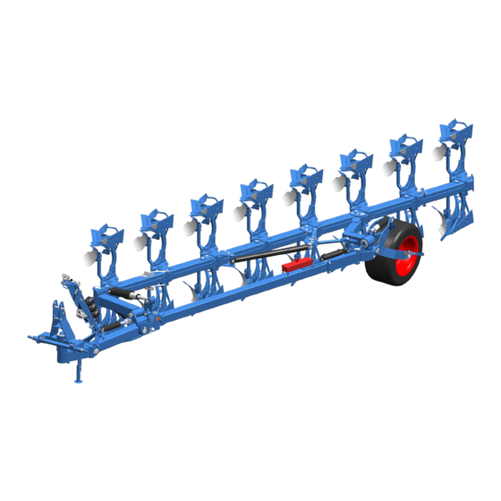
Layout and description LAYOUT AND DESCRIPTION Overview Transport position Working position 1 Headstock 5 Wheel 2 Hydraulic ram for traction increase 6 Frame device 7 Plough bodies 3 Turnover ram 8 Pre-ploughing tools: Skimmer 4 Stabiliser (trashboard, disc coulters not shown) 9 Lighting equipment - not shown... -
Page 37: Description
Layout and description Description 5.2.1 Headstock The headstock with top link pin and cross shaft conforms to ISO 730. Cross shaft L2/Z3 conforms to category 3N. Cross shaft L3/Z3 conforms to category 3. Cross shaft L3/Z4 conforms to category 4N. The top link pin conforms to category 3. -
Page 38: Stabiliser
Layout and description 5.2.4 Stabiliser The stabiliser (4) guides the wheel as well as supporting and pulling the frame. 5.2.5 Land wheel Large deep-tread land wheel for low ground pressure when ploughing. -
Page 39: Frame
Layout and description 5.2.6 Frame The frame supports the plough body. • Diamant: four working width settings • Diamant V: hydraulically infinitely adjust- able working width... -
Page 40: Plough Body
Layout and description 5.2.7 Plough body DuraMaxx The strips (1) or mould boards (2) are at- tached to the mould board (4) with hooks (3). Accordingly, replacement without tools is possible. - Page 41 Layout and description Dural The plough body consists of: • Mouldboard, made up of a shin (1) and a mouldboard (2), or slats (5). • Share, made up of a wing (3) and a point (4). • Frog (6) • Landside (7)
-
Page 42: Additional Tools
Layout and description 5.2.8 Additional tools The following additional tools are available as accessories: Trashboard (1) Skimmer (2) Sword coulter (3) - Page 43 Layout and description Disc coulter (4) Version with smooth disc coulter (4), rigid leg (5). Version with toothed disc coulter (6), spring-loaded leg (7).
-
Page 44: Preparation Of The Tractor
Preparation of the Tractor PREPARATION OF THE TRACTOR Tyres The pressure - especially in the rear tractor tyres - must be equal. In heavy condi- tions it may be necessary to add wheel weights and/or water ballast. (See manu- facturer’s instructions). Lift Rods Adjust lift rods to equal length. -
Page 45: Hydraulic Equipment Required
Preparation of the Tractor Hydraulic equipment required The implement is supplied with separate hydraulic connections for each consumer as standard. The protecting caps on the hydraulic connections are coloured and the hydraulic connections themselves are marked alphanumerically. To activate the individual hydraulic devices listed below, the tractor must be equipped with the following spool valves: Consumer Single-acting... -
Page 46: Preparing The Implement
Preparing the implement PREPARING THE IMPLEMENT Headstock attachment position Swivelling the headstock (2) allows the dis- tance between the plough’s pivot point and the tractor’s rear axle to be increased or reduced respectively. The distance must be kept as small as possible to minimise the side pull. -
Page 47: Stand Length
Preparing the implement Stand length The length of the stand (1) must be adjust- ed so that the cross shaft is parallel to the ground when the implement is parked in the working position. See «Set the length, page 52». The stand (1) is adjusted to the implement in the correct length already ex... -
Page 48: Implement With Traction Increase Device
Preparing the implement Implement with traction increase device The headstock (2) is connected to the plough frame by a joint. When a traction increase device is installed, it is also con- nected by a hydraulic ram (5). So that the plough can be attached and removed from the tractor safely, the pres- sure supply to the hydraulic ram is inter- rupted by the shut-off valve (4). -
Page 49: Attaching The Implement
Attaching the implement ATTACHING THE IMPLEMENT General Risk of fatal injury due to unsecured connection between lower link and cross shaft If the connection between the lower link and cross shaft is not se- DANGER cured, the pivot on the cross shaft may slip out of place. This may cause death or injury to other road users while the im- plement is being transported. - Page 50 Attaching the implement Risk of accident from spurting hydraulic fluid Hydraulic fluid which escapes under high pressure may penetrate your skin and cause severe injuries. If injuries occur, call a doctor immediately − Before connecting the hydraulic hoses to the tractor hydraulics, WARNING check that the hydraulics are depressurised on the tractor and device.
-
Page 51: Procedure
Attaching the implement Procedure − Before attaching the implement, switch the hydraulic system for the tractor’s three-point linkage to position control. − Reverse the tractor so that it is posi- tioned squarely in front of the implement. o The lower links are in front of the cross shaft. - Page 52 Attaching the implement − Release the stand (6). To do this, pull the handle on the spring-loaded locking pin (7). − Pivot the stand (6) upwards and secure it with the locking pin (7). o Ensure that the locking pin (7) engages in the hole (8).
- Page 53 Attaching the implement − Turn the plough into the left-handed po- sition. − Fit the bolt (5) in the angular adjustment mechanism for the right-handed side. To insert the bolt (5) into the holder, bend the sprung side piece downwards as shown.
-
Page 54: Uncoupling The Implement
Uncoupling the implement UNCOUPLING THE IMPLEMENT Risk of injury when detaching the implement WARNING There is a risk of crushing body parts between the tractor and im- plement. Secure the tractor to prevent it from rolling away accidentally, oth- erwise there is a risk of crushing. Never activate the tractor hydraulic system if somebody is stand- ing between the tractor and the implement. -
Page 55: Work Instruction
Uncoupling the implement Work instruction − Rotate the plough to the left-turning posi- tion. − Remove the screw (1) of the angular ad- justment for the right-hand side. The screw (1) for the right-turning side is stored in the toolbox when not in operation. - Page 56 Uncoupling the implement − Lower the lower link until the stand is on the ground. − Unlock and disconnect the top link pin (4). − Insert the top link pin into the hole (5) of the joint at the stabiliser. The top link prevents the headstock from...
- Page 57 Uncoupling the implement Implement with traction increase device: When the implement is detached, depres- surise the traction increase device. − Use the appropriate spool valve to raise the lower link. Release pressure as follows via the spool valve of the depth wheel: The shut-off valve (6) is open.
- Page 58 Uncoupling the implement − Disconnect the hydraulic hoses from the tractor. − Install the protecting caps. − Position the top link in the tractor-sided holder. See operating instructions from the tractor manufacturer. − Remove lower link from the cross shaft (2).
-
Page 59: Driving On Public Highways
Driving on public highways DRIVING ON PUBLIC HIGHWAYS 10.1 General information A proper lighting system, identification and equipment must be on the implement, if it is to be transported on public roads. The country-specific valid laws and regu- lations pertaining to driving on public roads must be observed. 10.2 Preparation for driving on public roads Before commencing a journey on public roads, the following components and... - Page 60 Driving on public highways − Open the shut-off valve (4) on the damper on the chassis. − Move the pin in the depth limiter (5). o Ensure that there is a clearance of at least A = 3 cm to guarantee sufficient spring travel.
-
Page 61: Transport
Driving on public highways 10.3 Transport 10.3.1 Permissible transport height The implement may be too high. This poses an increased risk WARNING when driving under bridges, entrances and high-voltage power lines. The maximum permissible transport height is 4 m. o Ensure that the implement does not exceed the maximum permissible transport height of 4 m. -
Page 62: Lighting Equipment And Identification
Driving on public highways 10.4 Lighting equipment and identification Before driving on public roads, the respective lighting equipment and identification must be attached in accordance with national regulations. 10.4.1 Attaching the lighting equipment − Rotate the frame to the half-rotated posi- tion = centre position −... - Page 63 Driving on public highways • Variant 1: − Secure the lighting support with a linch pin (9). − Use the plug (10) to connect the lighting equipment according to the supplied var- iant. • Variant 1 • Variant 2 The lighting equipment must be disassembled during the turning process and when working in the field.
-
Page 64: Testing The Lighting Equipment
Driving on public highways 10.4.2 Testing the lighting equipment Test the lighting equipment. − Operate the direction of travel indicator in the tractor o Make sure the control lamp of the tractor’s direction travel indicator and the control lamp of implement’s direction travel indicator flash at the same... -
Page 65: Identifications
Driving on public highways 10.4.3 Identifications − Depending on country specific require- ments, attach identifications, e.g. regis- tration plates, SMV triangle or other re- flectors, and connect them using the plug (10). • Variant 1 • Variant 2... -
Page 66: Operation
Operation OPERATION 11.1 Rotating the frame − Refer to the safety and protective measures, see page 15. DANGER − Before each rotation, ensure that there are no persons in the turning and swivelling area of the plough. − Only operate the slewing gear from the tractor seat. −... -
Page 67: On-Land Ploughing (Of)
Operation spool valve to the opposite pressure po- sition = second pressure position. − Set the spool valve to T for the depth wheel. − Continue to pressurise until the previ- ously set level of system pressure for the traction increase device been... -
Page 68: Converting From F Operation To O Operation
Operation 11.2.2 Converting from F operation to O operation − Release the pin (1). − Remove the pin (1). − Place the pin (1) in the free hole in the link (2). − Secure the pin (1) with the linch pin. −... -
Page 69: Converting From O Operation To F Operation
Operation − Turn the frame to the centre position. − Release the stop (7) on the depth wheel (8). − Move the stop in the direction of the ar- row (7). − Secure the stop (7) again. 11.2.3 Converting from O operation to F operation −... - Page 70 Operation − Release the pin (1) and remove it. − Lock the link (2) and turning mechanism (10) together using the pin (1). The pin (1) must be fitted as shown. − Secure the pin (1) with the linch pin. −...
-
Page 71: Turning On The Headland
Operation 11.3 Turning on the headland DANGER Risk of damage to components If an implement is not raised all the way, there is a risk of damage to components if the tractor is not turned correctly at the headland. Before turning at the headland, the implement must be raised all the way before cornering in order to prevent damage to the implement. -
Page 72: Damper On Land Wheel
Operation 11.4 Damper on land wheel During in-furrow ploughing in the field, the damper (1) does not function, as the bracket (2) is resting on the pin (3) for depth limitation. When travelling on the headland and on the road, the pin (3) for depth limitation must be able to move freely. -
Page 73: Adjustments
Adjustments ADJUSTMENTS − Read and follow the section entitled "Safety and protection measures. CAUTION • The implement may only be used, maintained and repaired by people who are familiar with it and who are aware of the haz- ards involved. •... -
Page 74: Front Furrow Width
Adjustments 12.1 Front furrow width The front furrow width is set with the spin- dle (1). • Front furrow too narrow − Turn the spindle (1) to make it longer. • Front furrow too wide − Turn the spindle (1) to make it shorter. A double-acting hydraulic cylinder can be used to set the front furrow width from the tractor seat instead of using the spindle... -
Page 75: Distance From The Tractor To The Edge Of The Furrow (Online Version Only)
Adjustments 12.2 Distance from the tractor to the edge of the furrow (online version only) The distance from the tractor to the edge of the furrow can be adjusted in on-land ploughing using the spindle (1). Not enough distance: − Turn the spindle (1) to make it shorter. Too much distance: −... -
Page 76: Working Depth
Adjustments 12.3 Working depth − Take off the pin's (1) grip safety on the frame side. − Insert the pin (1) into the right hole on the adjustment plates (2) for the required working depth. • Hole 1 => minimum working depth •... -
Page 77: Tilt
Adjustments During in-furrow ploughing, the land wheel is moved to the centre position and locked with the stop (3). − Move the stop (3) up and forward until the tab (4) of the bracket (5) slots into the recess (6) of the stop. 12.4 Tilt During work, the stalks of the body should be more or less vertical in relation to... -
Page 78: Working Width Per Body (Diamant)
Adjustments 12.5 Working width per body (Diamant) The working width can be set to 4 posi- tions. Working width per body: 33, 38, 44 or 50 cm. The working width is adjusted by moving the individual bodies. − Loosen the bolt (1). −... -
Page 79: Working Width For Each Body (Diamant V)
Adjustments 12.6 Working width for each body (Diamant V) The working width of the Diamant V is infi- nitely adjustable. Adjustment range: 30cm - 55cm for each body. The working width is changed via the hy- draulic ram (1). − Retract the hydraulic ram => reduced working width −... -
Page 80: Side Pull
Adjustments 12.7 Side pull − Set the tractor’s three-point linkage for working. The recommended distance between the tractor’s rear wheels in in-furrow mode is roughly 1.3 m - 1.5 m. The side pull to the ploughed side can be reduced by increasing the distance be- tween the tractor’s rear wheels. -
Page 81: Draw Point Height (Only In On-Land Configuration)
Adjustments 12.8 Draw point height (only in on-land configuration) When a crawler tractor is used, it is im- portant for the chassis to apply the same ground pressure over its entire length dur- ing operation. − Adjust the height of the draw point. •... -
Page 82: Pitch Angle
Adjustments 12.9 Pitch angle 12.9.1 DuraMaxx plough body The pitch angle is adjusted via the position of the eccentric plate. The bodies are fitted at a centre pitch angle relative to the ground. The eccentric plate (1) is in the centre position, see notch on the eccentric plate. - Page 83 Adjustments • Smaller pitch angle: − Rotate eccentric plate (1) upwards by 90°. Notch points in the direction of the plough frame. o Improved depth control. − After adjusting the pitch angle, tighten nuts (2) and (3). Tightening torques see «Tightening torques, page 122»...
-
Page 84: Dural Plough Body
Adjustments 12.9.2 DURAL plough body The bodies are fitted at a centre pitch - angle relative to the ground. If required, the pitch angle can be changed using the two adjusting screws (1a, 1b). − Undo the screw (2). The bolted connection (3) is used as a piv- ot when adjusting the pitch angle. - Page 85 Adjustments All plough bodies must be adjusted to the same pitch angle. − Adjust pitch angle of the first and last plough body. − Measure distance between point and plough frame (= reference dimension) − Adjust the remaining plough bodies ac- cording to this reference dimension.
-
Page 86: Landside
Adjustments 12.10 Landside For better guidance on slopes, move land- side DMV1 (1) to a lower position (only possible with DuraMaxx plough bodies.) − Loosen the bolt − Remove the bolt (2). − Move the landside (2) to the lower posi- tion. -
Page 87: Sword Coulter
Adjustments 12.11 Sword coulter The landside wedge must be removed be- fore the sword coulter is attached. − Unscrew countersunk screw (5) and hexagon bolt (4). − Remove landside wedge (1) and hexa- gon bolt (4). − Attach sword coulter (2) in front of the landside (3) and screw into place using both hexagon bolts (5). -
Page 88: Trashboard
Adjustments 12.12 Trashboard DuraMaxx version − Align trashboard (1) with holder (2) via the slots (4) and screw onto the leg (3). All trashboards must be set in the same position. - Page 89 Adjustments Dural version − Align trashboard (1) with holder (2) via the slots (4) and screw onto the mould- board (3). − Adjust trashboard to prevent crop resi- due between the slats or mouldboard and trashboard o The edge of the trashboard is positioned on the mouldboard or mouldboard slat.
- Page 90 Adjustments The support bolt (4) supports the trash- board against the leg. − Secure support bolt (4) with lock nut (5), see view Y. The installation position of the support bolt and the lock nut may vary de- pending body shape used.
-
Page 91: Subsoilers
Adjustments 12.13 Subsoilers Subsoilers are mounted to the basic body and to the leg at DuraMaxx and Dural re- spectively. The depth of the subsoilers can be adjusted. The leg (2) is protected against wear by the leg guard (3). Both the leg guard (3) and the gudgeon (1) can be replaced after removing the nut (4). -
Page 92: Wide Furrow Cutter
Adjustments 12.14 Wide furrow cutter The wide furrow cutter (1) widens the fur- row made by the last body. It can be used in light to medium soils without any prob- lems. It cannot be used effectively in heavy soil conditions. The wide furrow cutter (1) is attached to the last body on the plough. -
Page 93: Working Depth
Adjustments In conjunction with the projection angle ad- justment, the swivel bracket (2) can be at- tached to the side of the bracket (3) in three different positions (a, b or c). This allows the skimmers to be always in an op- timum side position, even in conjunction with disc coulters. -
Page 94: Turning Forwards Or Backwards
Adjustments 12.15.3 Turning forwards or backwards By turning the leg (6) forwards or back- wards, optimise the position of the skim- mer (1): • Backwards = More clearance between skimmer and the plough body in front. • Forwards = More clearance between skimmer and the associated plough - body (e.g. -
Page 95: Projection Angle Adjustment
Adjustments 12.15.4 Projection angle adjustment On the standard version the projection an- gle of the skimmers cannot be adjusted. On the version with projection angle ad- justment the skimmers (1) are connected to their flat stalks (2) and the swivel brack- et (3) is connected by a pivot to the bracket (4). -
Page 96: Disc Coulters
Adjustments 12.16 Disc coulters 12.16.1 General information The disc coulters have been set for operation at the factory with the following ad- justment dimensions. Make subsequent adjustments to the disc coulters only when changing the setup state. The working depth (T) of the disc must be set between 7 cm and 12 cm. -
Page 97: Working Depth
Adjustments 12.16.2 Working depth The working depth of the disc coulter is ad- justed as follows: − Undo the screw (2). − Swivel coulter arm (1) as required. Rigid disc coulter Ensure that the teeth on the coulter arm (1) mesh exactly with the adjacent toothed bracket (3) before tightening the screw (2). -
Page 98: Side Distance
Adjustments 12.16.3 Side distance The lateral clearance between the coulter disc (1) and the landside on the plough body is adjusted by swivelling the coulter stalks (2). − Undo the screw (3). Adjust lateral clearance. − Move coulter stalk (2) in the slot (a) until the required position has been reached. -
Page 99: Swivel Restriction
Adjustments 12.16.4 Swivel restriction The lateral swivel area of the disc coulters (1) is restricted by the adjusting piece (2). The adjusting piece must be adjusted so that the disc coulter, when swivelled in, is parallel with the landside of the plough body at a distance of 2 cm to 3 cm. - Page 100 Adjustments Version disc coulter in front of skimmer o Adjust the adjusting piece (2) so that the disc coulter (1), when swivelled in, points to- wards the point on the skimmer (4). Spring-loaded disc coulter (version T) Version without skimmer o Adjust the adjusting piece so that the disc coulter, when swivelled in, points towards the...
-
Page 101: Land Wheel
Adjustments 12.17 Land wheel 12.17.1 General The land wheel (1) is part of the standard scope of delivery of implements for on-land ploughing. During turning, gravitational force causes the wheel to turn away from the stop (2) to the opposite working position. A return spring (4) then turns the land wheel back to the working position against the counter stop (3). -
Page 102: Setting The Return Spring
Adjustments 12.17.2 Setting the return spring If the land wheel does not turn correctly, the problem can be solved by adjusting the return spring (4) as follows: • Land wheel not turning back to working position => − Increase the spring force of the return spring (4) by turning the adjusting screw (5) clockwise. -
Page 103: Overload Safety Devices
− Loosen screw (2) on the leg. − Lift up implement until the plough body swivels back into its working position. − Have a new shear bolt (1) ready. Diamant 11 T... - Page 104 − Carefully tighten shear bolt (1) and the screw (2). See «Tightening torques, pa- ge 122». Shear bolt Plough type Dimension Diamant 11 M14x85 - 10.9 M 16x100 LS 70X25 – 12.9 Diamant 11 V Diamant 11 T M 14x70 LS 51x15 - 10.9 Diamant 11 VT...
-
Page 105: Hydromatic Hydraulic Overload Safety Device
Overload safety devices 13.2 Hydromatic hydraulic overload safety device − Read and follow the “Safety measures and precautions” sec- tion, and the specific safety information “Hazards caused by hy- draulic systems”. − Never stand in the plough body trip zone while the plough is operating. -
Page 106: Setting The Release Force
Overload safety devices 13.2.2 Setting the release force Different operating pressures can be set using the hydraulic overload safety de- vice: choose a low operating pressure for shallow and light soil conditions and a higher operating pressure for heavy soil conditions. There is a shut-off valve (1) underneath the pressure gauge (2). - Page 107 Overload safety devices To reduce the pressure: − Set the spool valve for the wheel to P; the wheel (3) is lowered. − Open the shut-off valve (1). The display on the pres- sure gauge (2) shows the final pressure as soon as the wheel has been low- ered.
- Page 108 Overload safety devices After connecting the adjusting valve unit (1) to a spool valve on the tractor, the sys- tem is ready to operate with the factory set maximum and minimum operating pres- sure. If necessary, these operating pres- sures can be individually adjusted using the dials (2) and (3) and read at the pres- sure gauge (4): •...
- Page 109 Overload safety devices Setting the maximum operating pressure: Increasing the maximum operating pres- sure: − Turn the rotary knob (2) clockwise. Reducing the maximum operating pres- sure: − Turn the rotary knob (2) anticlockwise. Setting the minimum operating pressure: Increasing the minimum operating pres- sure: −...
-
Page 110: Depressurising The Hydraulic System
Overload safety devices 13.2.3 Depressurising the hydraulic system Always depressurise the hydraulic system before performing maintenance or re- pair work, for instance. To do so, pressure must be released via the spool valve of the depth wheel as follows. Risk of injury due to incorrectly performed maintenance work DANGER Incorrect maintenance and repair work jeopardise operational safety. - Page 111 Overload safety devices Equipment without traction increase device − Set the spool valve to P. o The depth wheel is raised. Set the chassis to the lowest working depth to ensure the plough bodies with overload safety device have sufficient clearance to the ground and can be low- ered after releasing the pressure.
- Page 112 Overload safety devices Equipment with traction increase device: − Release pressure in the traction in- crease device as follows via the spool valve of the depth wheel: − The shut-off valve (1) is open. − Set the spool valve for the depth wheel to P and keep hold of it until the pres- sure gauge indicator (2) drops to 0 bar.
- Page 113 Overload safety devices − Set the spool valve to T and keep hold of it until the pressure gauge indicator (5) drops to 0 bar. o The depth wheel is lowered. − Open the shut-off valve (4) for overload safety device o The overload safety device is depressurised.
- Page 114 Overload safety devices Equipment with comfort valve (4) − Set the spool valve to P. o The depth wheel is raised. Set the chassis to the lowest working depth to ensure the plough bodies with overload safety device have sufficient clearance to the ground and can be low- ered after releasing the pressure.
-
Page 115: Pressurising The Hydraulic System
Overload safety devices 13.2.4 Pressurising the hydraulic system Pressurise the hydraulic system to restart after, e.g., maintenance or repair work. To do so, pressure must be built up via the spool valve of the depth wheel as fol- lows: Equipment without traction increase device −... - Page 116 Overload safety devices Equipment with traction increase device − Hydraulic pipe assemblies are connect- ed to the tractor. Open the shut-off valve (1) of the traction increase device. − Set the required pressure for the traction increase device. See «Changing, page 126».
- Page 117 Overload safety devices Equipment with comfort valve: − Set the spool valve to P. o The depth wheel is raised. − Tighten the screw (2) of the comfort valve (1) and use the nut to secure it. − Set the spool valve for the comfort valve of the overload safety device to P.
-
Page 118: Attachment Arm
Attachment arm ATTACHMENT ARM − Read and follow the «Safety measures and precautions, page CAUTION 15». The attachment arm pivots into the catch position as a result of spring tension. − Ensure that you maintain an adequate safety distance. − Connect the attachment arm (1) to the front of the frame (2). -
Page 119: Put The Implement Out Of Operation
Put the implement out of operation PUT THE IMPLEMENT OUT OF OPERATION 15.1 Shutting down the implement in an emergency − In an emergency shut down the implement via the tractor. − Switch the tractor engine off. − Remove the ignition key. Damage caused by improper storage of the implement If incorrectly or improperly stored, the implement may be dam- CAUTION... -
Page 120: Maintenance And Repairs
Maintenance and repairs MAINTENANCE AND REPAIRS 16.1 Special safety instructions 16.1.1 General Risk of injury when carrying out maintenance and repair work There is always the risk of injury when carrying out maintenance and repair work. WARNING − Use suitable tools, suitable climbing aids, platforms and support elements. -
Page 121: Immobilise The Implement For Maintenance And Repairs
Maintenance and repairs 16.1.3 Immobilise the implement for maintenance and repairs Risk of accidents when tractor starts up Injuries may occur if the tractor starts moving during maintenance and repair work. − Switch off the tractor engine before carrying out any work on the WARNING implement. -
Page 122: Protective Equipment
Maintenance and repairs 16.1.6 Protective equipment CAUTION Risk of accident due to working without protective equipment There is always an increased risk of accidents when carrying out maintenance work and repairs. − Always wear appropriate protective equipment. 16.1.7 Utilised tool Risk of accident due to use of unsuitable tool WARNING If working with an unsuitable or defective tool, there is a risk of ac-... -
Page 123: Environmental Protection
The hydraulic hoses must be replaced at the latest 6 years after the date of manufacture. Use hydraulic ho- ses authorised by LEMKEN only. Safety equipment − Check that the safety equipment functions properly. -
Page 124: Weekly Inspection
Maintenance and repairs 16.3.3 Weekly inspection Check What to do? Wheel nuts − Check that all wheel nuts are tight and, if re- quired, retighten the wheel nuts to the appro- priate torque. Screw connections − Retighten all other bolts and nuts on the device to the appropriate torque. -
Page 125: Bolts And Nuts Made Of Steel
Maintenance and repairs 16.4.2 Bolts and nuts made of steel Strength category Diameter 10.9 12.9 [Nm*] [Nm*] [Nm*] 13,6 16,3 23,4 32,9 39,6 M 10 46,2 64,8 77,8 M 12 80,0 M 14 M 16 M 20 M 24 1112 M 30 1314 1850... -
Page 126: Check The Connections To The Tractor
Maintenance and repairs 16.5 Check the connections to the tractor 16.5.1 Hydraulic connections Risk of accidents due to escaping hydraulic fluid Hydraulic fluid which is ejected under high pressure (hydraulic oil) WARNING can penetrate the skin and cause serious injuries. In the event of injuries, consult a doctor immediately. -
Page 127: System Pressure Of The Traction Increase Device
Maintenance and repairs 16.6 System pressure of the traction increase device 16.6.1 Reading the system pressure If the system pressure of the traction in- crease device (1) has dropped too low, it must be increased. The system pressure can only be checked when the implement is mounted on the tractor. -
Page 128: Changing The System Pressure
Maintenance and repairs 16.6.2 Changing the system pressure Danger if the system pressure is too high, and danger from WARNING leaking hydraulic fluid The system pressure must not exceed 200 bar. − Do not disconnect the filling hose until the shut-off valve (2) has been closed and locked and the pressure in the filling hose has been released. -
Page 129: Air Pressure Of The Tyres
Maintenance and repairs o Setting range for the system pressure: 80 – 200 bar. The display on the pres- sure gauge (3) shows the final system pressure as soon as the wheel has been lowered. To reduce the pressure: − Turn the adjustment screw on the valve block anticlockwise. -
Page 130: Lubrication Chart
Maintenance and repairs 16.8 Lubrication chart Every Before and after prolonged operating hours winter break Turnover device and stabiliser bearings Cylinder eyes Linkage bearings Turnbuckle Wheel arm bearings Land wheel bearings Pivot brackets and control rod (Diamant V only) Traction increase unit... - Page 131 Maintenance and repairs The bearing tube of the bolt (1) is lubricat- ed via the lubricating line (2).
-
Page 132: Troubleshooting
Troubleshooting TROUBLESHOOTING 17.1 Plough insertion and guidance, slip Fault Reason Remedy Plough not staying in ground. Insufficient insertion − Insert the body = reduce force. the distance between the coulter tip and the plough frame. See «Pitch angle, page 80». Plough is not being inserted into the Coulter contact an- −... -
Page 133: Technical Data
Frame height Body clearance Model ness frame (mm) furrows Diamant 11 T / 11 VT 5 L 100 160x160x10 Diamant 11 T / 11 VT 5+1 L 100 160x160x10 Diamant 11 T / 11 VT 6 L 100 160x160x10 Diamant 11 T / 11 VT 6+1 L 100... -
Page 134: Permissible Output Range
18.3 Permissible output range Number of Name Tractor output from … on furrows Diamant 11 / 11 T Diamant 11 V / 11 VT 18.4 Weights Body clearance Diamant 11 2.584 2.834 2.830 3.080 3.076 3.326 3.322 3.572 Diamant 11 T 2804 3.103 3.094 3.393 3.384 3.683... -
Page 135: Noise, Airborne Sound
Noise, Airborne Sound NOISE, AIRBORNE SOUND The noise level of the implement does not exceed 70 dB (A) during work. NOTES As the version of equipment is depending from the order, the equipment of your implement and its description concerned may deviate in some cases. To ensure a continuously updating of the technical features, we reserve the right to modify the design, equipment and technique. -
Page 136: Index
Index INDEX Additional tools ..................... 40 ADJUSTMENTS ....................71 Air pressure ......................127 Axle loads ......................24 Breitfurchenmesser ....................90 Check Chains ....................... 42 Damper ......................... 70 Disc coulters ......................94 Draw point height ....................79 Dural ........................39 DURAL plough body ..................... 82 DuraMaxx ...................... - Page 137 Index PREPARING THE IMPLEMENT ................44 Projection angle adjustment ................. 93 Repairs ....................... 118 Return spring ...................... 100 Rotary cylinder ...................... 35 Shearing protection .................... 101 Skimmers ......................90 Stabiliser ....................... 36 Stand ......................45, 52 Subsoilers ......................89 Sway Blocks ......................42 Sword coulter ......................
Need help?
Do you have a question about the Diamant 11 and is the answer not in the manual?
Questions and answers