
Related Manuals for LEMKEN Zirkon 12 K


Summary of Contents for LEMKEN Zirkon 12 K
- Page 1 Operating Instructions Power Harrow Zirkon 12 K - en - Item no. 17510865 02/04.21 LEMKEN GmbH & Co. KG Weseler Straße 5, 46519 Alpen / Germany Telephone +49 28 02 81 0, Fax +49 28 02 81 220 lemken@lemken.com, www.LEMKEN.com...
- Page 3 However, this brief instruction is not a substitute for thorough study of the operating instructions. These operating instructions will help to familiarise you with the LEMKEN GmbH & Co. KG device and the options available for using it.
- Page 4 Remember that you should only use genuine LEMKEN spare parts. Reproduction parts have a negative influence on the function of the device, have a shorter ser- vice life and present risks and hazards that cannot be estimated by LEMKEN GmbH & Co. KG. They also increase the maintenance costs.
-
Page 5: Table Of Contents
CONTENTS General information ....................10 Liability ......................... 10 Guarantee ........................10 Copyright ........................11 Optional accessories ....................11 Symbols used in the Operating Instructions ............12 Hazard classes ......................12 Information........................12 Environmental protection ................... 12 Indication of passages ....................13 Safety measures and precautions ................. - Page 6 Operation on public highways ................... 23 3.9.1 Lighting system and identification ................23 3.9.2 Requirements of the tractor ..................23 3.9.3 Axle loads ........................24 3.9.4 Check before departure ..................... 28 3.9.5 Correct behaviour in road traffic ................29 3.10 Obligation of the operator ..................29 3.11 Safe use of the implement ..................
- Page 7 Preparation of the Tractor ..................44 Tyres ..........................44 Lift Rods ........................44 Check chains/stabilisers on the three-point linkage ..........44 Self-levelling ........................ 44 Hydraulic equipment required ..................44 Power sources required ..................... 45 Three-point linkage ..................... 46 Hydraulic system ......................47 6.8.1 Transport ........................
- Page 8 10.4 Folding in and out ....................... 64 10.4.1 Folding in ........................ 64 10.4.2 Folding out......................65 11 Settings ........................67 11.1 Cardan shaft ........................ 68 11.1.1 General ........................68 11.1.2 Changing the distance between the implement and the tractor ......69 11.1.3 Shortening the cardan shaft ...................
- Page 9 12.1 General ......................... 89 12.2 Setting the scrapers ....................90 12.3 Roller inclination ......................90 13 Mounting a LEMKEN seed drill ................91 13.1 Coupling elementsfor mounting a Solitair seed drill ..........91 14 Hydraulic three-point linkage ................. 92 14.1 Adjusting the hydraulic three-point linkage.............. 92 14.2 Attaching a mounted machine ...................
- Page 10 16.1.6 Working on the electrics ..................100 16.1.7 Working under the raised device ................101 16.1.8 Utilised tool ......................101 16.2 Environmental protection ..................102 16.3 Checking connections to the tractor ............... 103 16.3.1 Hydraulic connections ..................103 16.3.2 Electrical connections ................... 104 16.4 Maintenance intervals ....................
- Page 11 17 Troubleshooting ....................116 17.1 General information ....................116 17.1.1 Electrical equipment ..................... 116 17.1.2 Hydraulic equipment ..................... 116 18 TECHNICAL DATA ....................117 18.1 Additional trailer for OptiDisc .................. 117 19 Identification plate ....................118 20 Noise, Airborne Sound ..................119 21 Notes ........................
-
Page 12: General Information
Co. KG, in particular Section IX, shall apply. Liability. In line with the dimensions cited in these conditions the LEMKEN GmbH & Co. KG shall not be held liable for any personal or material damage, when such damage is caused by one or more of the following reasons: ... -
Page 13: Copyright
Infringements will result in a claim for damages. Optional accessories LEMKEN implements may be equipped with various accessories. The operating instructions below describe both series components and optional accessories. Please note: These accessories will vary depending on the type of equipment. -
Page 14: Symbols Used In The Operating Instructions
Symbols used in the Operating Instructions SYMBOLS USED IN THE OPERATING INSTRUCTIONS Hazard classes The following symbols are used in the Operating Instructions for particularly im- portant information: DANGER Denotes an imminent hazard with high risk, which will result in death or severe physical injury, if not avoided. -
Page 15: Indication Of Passages
Symbols used in the Operating Instructions Indication of passages The following symbols are used for particular passages in the operating instruc- tions: Indicates work steps Indicates enumerations... -
Page 16: Safety Measures And Precautions
Safety measures and precautions SAFETY MEASURES AND PRECAUTIONS General safety instructions for the operator are specified in the chapter entitled «Safety measures and precautions». At the start of some main chapters the safety instructions, which refer to all work to be carried out in this chapter, are listed to- gether. -
Page 17: Safety Features Of The Device
Safety measures and precautions Safety features of the device To protect the operator and the device, the device is equipped with special safety features in accordance with country specific requirements. Always keep all safety devices in working order. Safety and warning signs 3.4.1 General information The implement features all equipment which ensures safe operation. - Page 18 Safety measures and precautions Before carrying out maintenance or repair work, switch off the engine and remove key. Do not remain in the operating and swivel area of the implement. Danger of crushing. Danger through moving machine parts. The power takeoff shaft drive-through runs to the right.
-
Page 19: Meaning Of Other Symbols
Safety measures and precautions Keep out of the folding area of the device. Do not touch any moving machine parts. Wait until they have come to a standstill. Hot surfaces When the three-point power lift is activat- ed, stay outside of the lifting range of the three-point suspension. - Page 20 Safety measures and precautions Hydraulic connections Rotor speeds Working depth adjustment...
-
Page 21: Symbol Positions
Safety measures and precautions 3.4.4 Symbol positions Special safety instructions Risk of injury due to non-observance of the currently valid occupational safety guidelines If the currently valid occupational safety guidelines are bypassed WARNING or safety equipment is rendered unusable when handling the de- vice, there is a risk of injury. - Page 22 Safety measures and precautions Risk of injury due to foreign objects ejected at high speed WARNING During work there is a risk of injury to the face and body by lumps of earth, soil constituents or stones ejected at high speed. ...
-
Page 23: Danger Areas
Safety measures and precautions Danger areas Moving danger area WARNING The danger area of the implement moves with the implement dur- ing operation. While the implement is being operated, persons are not permitted in front of the actual danger area because the danger area moves with the implement. -
Page 24: Danger Area When Folding In And Out
Safety measures and precautions 3.6.2 Danger area when folding in and out Residual risks Residual risks are particular hazards which occur when handling the device and which cannot be eliminated despite a design in accordance with safety require- ments. Residual risks are not usually obvious and may be the source of a potential injury or health hazard. -
Page 25: Hazard Caused By Hydraulic Systems
Safety measures and precautions 3.7.2 Hazard caused by hydraulic systems There is a risk of injury to body parts, in particular the face, eyes and unprotected areas of skin, caused by burns and contamination with hydraulic fluid due to hot/pressurised hydraulic fluid spraying out of leaking joints or lines, ... -
Page 26: Axle Loads
Safety measures and precautions Risk of accidents due to inadequate steerability A tractor which is too small or which has inadequate front ballast cannot be manoeuvred safely or steered with adequate tracking WARNING stability. As a result, the driver or other road users may be injured or killed. - Page 27 Safety measures and precautions Data from tractor operating instructions Take the following data from your tractor's operating instructions: Abbreviation Data Tractor kerb weight (kg) _______ kg Front axle load (kg) of empty tractor _______ kg Rear axle load (kg) of empty tractor _______ kg Data from implement operating instructions ...
- Page 28 Safety measures and precautions Data to be determined through remeasuring are Determine the following data through remeasuring: Abbreviation Data Distance (m) between centre of gravity for front _______ m mounting implement or front weight and centre of front axle Tractor wheelbase (m) _______ m Distance (m) between centre of rear axle and centre...
- Page 29 Safety measures and precautions Calculation of actual front axle load T V tat x b – G x (a + b) + T x (c + d) V tat Enter the value for the calculated actual front axle load and the permissible front axle load as given in the tractor's operating instructions into the table.
-
Page 30: Check Before Departure
Safety measures and precautions Supplement for combination with OptiDisc coulter bar and additional trailer: In the case of an machine combination with an OptiDisc coulter bar and mounted additional trailer, the front axle of the tractor must be loaded with at least 20% of the tractor’s tare weight. -
Page 31: Correct Behaviour In Road Traffic
Safety measures and precautions 3.9.5 Correct behaviour in road traffic When driving on public highways, observe the relevant statutory national regu- lations. Driving behaviour, steering and braking performance are influenced by ballast weights. Ensure that the tractor has adequate steering and braking performance. ... -
Page 32: Safe Use Of The Implement
Safety measures and precautions Operate the device only in compliance with all connection and default values provided by the manufacturer! Use original spare parts only! 3.11 Safe use of the implement 3.11.1 General Before starting work, familiarise yourself with all the equipment and controls and how they work. -
Page 33: Personnel Selection And Qualifications
Safety measures and precautions Do not stand between the tractor and the implement. This is only permitted when the tractor is secured by the parking brake and wheel chocks to prevent it from rolling away. Always keep the implement clean to avoid the risk of fire. ... -
Page 34: Power Take-Off Operation
Safety measures and precautions When searching for leaks, use appropriate equipment because of the risk of in- jury. Fluid (hydraulic fluid) which escapes under high pressure can penetrate the skin and cause severe injuries. If injuries occur, call a doctor immediately. Risk of in- fection. - Page 35 Safety measures and precautions Caution: when the power take-off is switched off, the flywheel continues to run and presents a danger. Do not get too close to the implement during this peri- od. Work may be performed on it only when it is at a complete standstill. ...
-
Page 36: Handing Over The Implement
Handing over the Implement HANDING OVER THE IMPLEMENT As soon as the implement is delivered, ensure that it corresponds with the order package. Also check the type and completeness of any supplied accessories. When the device is handed over, your dealer will explain how it works. ... -
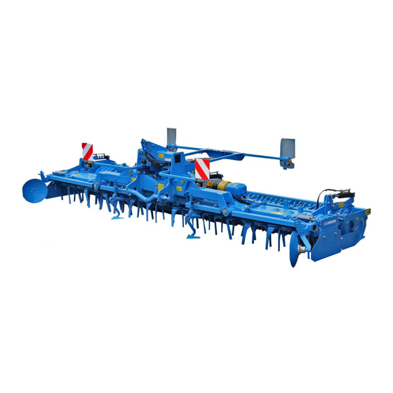
Page 37: Layout And Description
Layout and description LAYOUT AND DESCRIPTION Overview 1 Tines 9 Three-point linkage 2 Headstock 10 Roller 3 Trough 11 Levelling bar 4 Side shields 12 Feed discs 5 Side shield extension 13 Track marker 6 Lateral angular gearboxes 14 Wheelmark eradicators 7 Angular gearbox / optional 15 Lighting equipment (not shown) manual gearbox... - Page 38 Layout and description 16. Safety guard for tines and toothed packer roller 17. Protection bar for rotor shafts (sto- ne protection) 18. Cardan shafts...
-
Page 39: Description
Layout and description Description 5.2.1 Three-point tower The three-point tower with top link pin and drawbar D68 complies with ISO 730. Drawbar L3/Z3 complies with category 3. Drawbar L3/Z4 complies with category 4N. The top link pin complies with category 3. 5.2.2 Tines The specially hardened tines are bolted onto the rotors in the "towing"... -
Page 40: Side Blades
Layout and description 5.2.4 Side blades The height-adjustable side blades (1) and the extensions (2) prevent the outer tines from building up ridges. 5.2.5 Gearbox At the angular gearbox (basic equipment), the speed is set to 330 rotor rpm with the 1000 rpm PTO shaft or optionally to 440 rotor rpm. -
Page 41: Power Takeoff Shaft Drive-Through
Layout and description Above a working width of 5 m, the centre gearbox (1) is equipped with a fan (2) which provides additional cooling of the centre gearbox (1). The fan (2) is located inside the safety shield (3). 5.2.6 Power takeoff shaft drive-through The rotational speed and direction of rota- tion for the power takeoff shaft drive- though (1) corresponds to the rotational... -
Page 42: Hydraulic Three-Point Linkage
Layout and description 5.2.7 Hydraulic three-point linkage A hydraulic three-point linkage (1) is available for the combination with a seed drill or a coulter bar. The three-point linkage (1) corresponds to category 2 and is double-acting. The lifting force is 3,000 kg. The depth adjustment can be activated or deactivated via the shut-off valves (2). -
Page 43: Additional Trailer
Layout and description A hydraulic top link (5) is provided for the combination with OptiDisc. 5.2.8 Additional trailer Additional trailer for driving on public roads with the machine in combination with an OptiDisc coulter bar on the hydraulic three- point linkage. Mounting is carried out in the following se- quence: ... -
Page 44: Levelling Beam
Layout and description 5.2.10 Levelling beam The levelling beam ensures that the ground is evenly levelled. The levelling beam can be attached either in front of the knife tines or between the tines and the trailing roller. 5.2.11 Feed disc The feed disc (1) prevents ridge formation and allows the next pass to be lined up ac- curately. -
Page 45: Safety Devices
Layout and description Lighting equipment with warning boards is located at the front or rear or at both front and rear of the implement. 5.2.15 Safety devices Attach the safety guard before driving to ensure your safety whilst driving on public roads. -
Page 46: Preparation Of The Tractor
Preparation of the Tractor PREPARATION OF THE TRACTOR Tyres The pressure - especially in the rear tractor tyres - must be equal. In heavy condi- tions it may be necessary to add wheel weights and/or water ballast. (See manu- facturer’s instructions). Lift Rods Adjust lift rods to equal length. -
Page 47: Power Sources Required
Preparation of the Tractor For operation of the specific hydraulic equipment listed below, the tractor must be equipped with the following control units: Consumer Connection Single Double acting acting Tractor / Machine Colour Code Hydraulic folding with hyd- raulic transport locking de- P1 / T1 vice Hydraulic infinitely variable... -
Page 48: Three-Point Linkage
Preparation of the Tractor Three-point linkage Danger to life if three-point linkage category is too small If a drawbar or a top link pin is used with a category that is too small, these components may be overloaded and break. As a re- sult, the implement may fall down and injure or kill people in the DANGER immediate vicinity. -
Page 49: Hydraulic System
Preparation of the Tractor The table below shows the maximum permissible tractor power outputs and di- mensions for each category as per ISO 730-1. Tractor power out- Implement Pintle diameter Length of drawbar width (cm) Cat. of drawbar (mm) (shoulder distance) (mm) 400, 60 - 185 82 - 252... -
Page 50: Coupling And Uncoupling
Preparation of the Tractor 6.8.3 Coupling and uncoupling Lowering or raising the three-point linkage CAUTION If the three-point linkage moves uncontrollably due to an incorrect setting or operation, the operator may be injured. To couple or uncouple the device, always switch the tractor hydraulics to position control. -
Page 51: Preparing The Implement
Preparing the implement PREPARING THE IMPLEMENT CAUTION Safety footwear must be worn when carrying out adjustment work. Before using the implement, always check all the safety devices to ensure that they are functioning correctly. They should always be used or operated in ac- cordance with these operating instructions. -
Page 52: Wheelmark Eradicators
Preparing the implement Wheelmark eradicators The wheelmark eradicators (4) should be set to a depth which is approximately 5 cm below the surface of the wheel mark. They should always be slightly lower than the tines. See also the “Wheelmark eradicator settings”... -
Page 53: Attaching And Detaching
Attaching and detaching ATTACHING AND DETACHING Prior to attaching and detaching, always: DANGER Turn off the PTO shaft and the tractor engine. Apply the parking brake. Remove ignition key. Impairment due to unsuitable tractor If the tractor is not suitable for the machine: ... - Page 54 Attaching and detaching Risk of accident from spurting hydraulic fluid Hydraulic fluid which escapes under high pressure may penetrate your skin and cause severe injuries. If injuries occur, call a doctor immediately Before connecting the hydraulic hoses to the tractor hydraulics, WARNING check that the hydraulics are depressurised on the tractor and device.
- Page 55 Attaching and detaching Danger to life due to unsecured connection between lower link and cross shaft If the connection between the lower link and the cross shaft is not secured the pivot of the cross shaft may slip out. DANGER ...
-
Page 56: Detaching The Implement
Attaching and detaching Swing up the holder (2) of the cardan shaft (5). Secure the holder (2). Mount the warning boards and/or the lighting equipment if you have to drive on public roads to reach the field. ... - Page 57 Attaching and detaching If an additional trailer is mounted in combination with an OptiDisc coulter bar: Detach the additional trailer. Switch the hydraulic system of the trac- tor to position control. Fold out the machine fully. Lower the machine fully. In conjunction with the hydraulic three- point linkage: ...
-
Page 58: Information For Driving On Public Roads
Information for driving on public roads INFORMATION FOR DRIVING ON PUBLIC ROADS The machine can be equipped with com- plete lighting equipment with warning boards (1). The lighting equipment with warning boards must be mounted if the machine needs to be driven on public roads. - Page 59 Information for driving on public roads The additional trailer is mounted on the power harrow with the OptiDisc coulter bar for driving on public roads. The additional trailer is connected to the power harrow at two axles: Upper coupling point (1) ...
- Page 60 Information for driving on public roads Mounting the additional trailer Dismantle the lever (3) and keep it safe. Lift the power harrow until the catch hooks (4) on the power harrow are level with the upper coupling points (1). ...
- Page 61 Information for driving on public roads Slowly lift the power harrow until the ad- ditional trailer engages at the lower coupling point (2). Continue to lift the power harrow until the additional trailer is no longer in contact with the ground. ...
- Page 62 Information for driving on public roads If the implement is fitted with the long type of blade tine ZS 38 it has a transport width of more than 300 cm. You must comply with any national regulations relating to the permissible transport width.
- Page 63 Information for driving on public roads Track marker secured. The pin (5) is Track marker released. The pin is in in the hole (6). the hole (7).
-
Page 64: Operation
Operation OPERATION 10.1 Dismantling the additional trailer The additional trailer on the power harrow with a coulter bar is only intended for transport. The additional trailer is dismantled prior to working in the field. The additional trailer is connected to the power harrow at two axles: ... -
Page 65: Turning At The Headland
Operation Lower the power harrow until the additi- onal trailer rests on the ground with the support surface below the coupling point (2). Slowly drive the tractor-machine combi- nation forward until the upper coupling points (1) slide out of the catch hooks (4). -
Page 66: Power Take-Off
Operation 10.3 Power take-off The tractor's power take-off may not be switched on until the power harrow has been lowered until it is only a few centi- metres above the ground and the side blades (1) prevent any penetration into the rotating tools. -
Page 67: Folding Out
Operation Lock the tractor spool valve. If the implement is to be transported on public roads, lighting equipment must be provided and connected up. Fit the lateral protective equipment (3). 10.4.2 Folding out The machine may only be parked when folded out. ... - Page 68 Operation Before unfolding, switch to the “fold position” brief- ly so that the locking de- vice (1) unhooks smooth- Move the tractor spool valve to the 2nd pressure position = “unfold position” to unfold the side sections.
-
Page 69: Settings
Settings SETTINGS Risk of accident when performing adjustments When performing adjustments at the machine, there is a risk of crushing, cutting, trapping and hitting hands, feet and other body parts on heavy and partly spring-loaded and/or sharp-edged parts. Adjustments may only be performed by appropriately instructed DANGER personnel. -
Page 70: Cardan Shaft
Settings Risk of accident from freely rotating rollers DANGER If you climb on freely rotating rollers, there is a risk of crushing and clamping feet or legs between the freely rotating rollers and fixed device parts. Never climb on freely rotating rollers. DANGER Switch off the power take-off before carrying out adjustment work. -
Page 71: Changing The Distance Between The Implement And The Tractor
Settings 11.1.2 Changing the distance between the implement and the tractor Before changing the distance between the implement and the DANGER tractor, you must perform the following steps: Switch off the power take-off and tractor engine. Apply the handbrake. ... -
Page 72: Shortening The Cardan Shaft
Settings 11.1.3 Shortening the cardan shaft Pull the two cardan shaft halves apart. Hold the two cardan shaft halves against one another with the shortest possible gap between the tractor and the imple- ment. On the outer protective tube, mark the length you need to cut off. -
Page 73: Rpm Monitoring
Settings Append the operating instructions that came with the cardan shaft to these ope- rating instructions. Read the operating instructions for the cardan shaft before using it for the first time. To prevent rotation, ensure that the cardan shaft guard is secured by attaching the chains to a fixed point. - Page 74 Settings To do this, press and hold the switch (5) for 10 seconds red flashing = speed too low – acoustic signal Switch (5) to acknowledge the acoustic signal LED S3 green = implement is lowered red = implement is lifted Sensors S1 / S2 (6) detect the speed of one or two cardan shafts.
-
Page 75: Manual Gearbox
Settings 11.2 Manual gearbox 11.2.1 General Whether you achieve the effect you require will depend on a number of factors in- cluding the operating speed and rotor rpm. Select the lowest possible rpm which will still produce a good result. Too high a rotor rpm will cause unnecessary tine wear and increase fuel consumption. -
Page 76: Rotor Rpm
Settings 11.2.2 Rotor RPM The following rotor RPMs are possible depending on the power take-off speed: Rotor RPM Centre gear- Side gearbox (power take-off speed 1000) Angular gear Angular gear Gear 1 Gear 2 Angular gear Manual gearbox If the overload clutch of the cardan shaft responds too frequently in non-stony soils in conjunction with a power take-off speed of 540 rpm or 750 rpm, the power take-off shaft speed of 1000 rpm must be selected with a matching gear. - Page 77 Settings Recommended working speed depending on rotor speed Rotor speed per minute The rotor speed can be changed using the shifting lever. The 1000 rpm power take-off speed should always be selected. If a power take-off speed of 540 rpm or 750 rpm is used, then the input torque increases by 85 % or by 33 % and it does so at the same power transfer.
-
Page 78: Working Depth
Settings 11.3 Working depth The working depth of the power harrow is determined by the effect you want to achieve. In general, the power harrow should work as shallowly as possible. At the shallowest working depth setting, the power harrow is wider than 3 m when in the transport position. -
Page 79: Hydraulic Adjustment
Settings 11.3.2 Hydraulic adjustment - not possible in combination with a seed drill - Use the tractor spool valve to adjust the working depth via the hydraulic rams (1). 11.4 Blade tines The tines (1) can easily be replaced by hand as follows. -
Page 80: Blade Tines With Quick-Change System
Settings Hard-faced tines can be hard-faced on either the drag side or the grade side, as required. The opposite cutting side of the tines is specially hardened rather than hard-faced. 11.5 Blade tines with quick-change system Serious crush injuries Machine with a high dead weight can move downwards indepen- dently. -
Page 81: Changing The Direction Of Rotation Of The Rotors
Settings Install new tines with quick-change system in reverse order to the aforesaid procedure. Insert the new tines into the tine carrier (3). Insert the locking device (2) Rotate the locking device (2) 90° using an open-end wrench. When the tines of one rotor are installed on the adjacent rotor, this corresponds to a change of the tine position from the drag position to the grip position or vice ver- 11.6... - Page 82 Settings Check that the discs (6) have engaged. Screw in the centring nuts (4) slightly. Tighten the centring nuts (4) to a torque of 240 Nm using a 30 mm spanner. Replace the protecting caps (3). CAUTION ...
-
Page 83: Side Blade
Settings 11.7 Side blade Move the side blade into the working position before working with it. The height of the spring-mounted side blades (2) is to be adjusted such that they cover the rotating tools completely. When worn they must be lowered accordingly. Once they have been lowered, tighten the bolts (3) again. -
Page 84: Relocation At The Side
Settings 11.9.1 Relocation at the side Adjust the wheelmark eradicator (1) to the bout of the tractor as follows: Raise the implement to relieve the load- ing on the wheelmark eradicator (1). Undo the screw (3) in the holder (4). ... -
Page 85: Feed Discs
Settings 11.10 Feed discs The feed discs (1) prevent damming, facilitating precision during the next run. Mount the feed disc (1) console (2) on the outside of the bracket (3). 11.10.1 Relocation at the side On the bracket (3), move the feed disc (1) to the required working width. -
Page 86: Stop Bolts
Settings without levelling beam Mount the additional protective tube (3). 11.12 Stop bolts Stop bolts (1) are used to adjust the basic frame and the folded implement so that the side sections are vertical when they are in the transport position and do not knock against a mounted seed drill. -
Page 87: Levelling Beam
Settings Adjust the stop bolts (1). Tighten lock nuts (2). «Tightening torques, page 113. Check that the locking devices (3) have engaged. 11.13 Levelling beam CAUTION Before adjusting the levelling beam, always move the side blade into the working position. The circular spike harrow can be equipped at the rear or front with a levelling beam (1). -
Page 88: Rear-Mounted Levelling Beam
Settings 11.13.1 Rear-mounted levelling beam Set the levelling beam (1) using the rough- turning gauge (2) so that the lower edge of the levelling beam is about 2 cm over the surface of the ground! If too much soil is banked up, set the level- ling beam slightly higher! ... -
Page 89: Track Markers
Settings 11.14 Track markers CAUTION Before operating the track markers, always make sure that no persons are present in the danger zone. To ensure the implement runs more pre- cisely track-to-track, especially in combina- tion with a seed drill, track markers are available that can be bolted onto the carri- ers (2). -
Page 90: Shearing Protection
Settings Distance from middle of Distance from outer seeding Zirkon 12 K / 12 KA seed drill to the track groove coulter 400 cm 200 cm + ½ row distance 450 cm 225 cm + ½ row distance 500 cm 250 cm + ½... -
Page 91: Rollers
Rollers ROLLERS 12.1 General The implement can be fitted with a variety of rollers: Tube bar roller RSW 540 Trapeze packer roller TPW 500, TPW 600 Trapeze disc roller TSW 500 Rubber ring roller GRW 590 ... -
Page 92: Setting The Scrapers
Rollers 12.2 Setting the scrapers The adjustable scrapers (1) are adjusted by means of a bolt (2). Loosen the bolt (2). Set the bolt (3) to the position required. Tighten the bolt (2). See «Tightening torques, page 113». 12.3 Roller inclination If necessary, the inclination of trapeze rollers TPW and TSW, toothed packer rol-... -
Page 93: Mounting A Lemken Seed Drill
(2). Bolt the coupling elements as shown here onto the power harrow's three-point tower. Mount the LEMKEN Solitair seed drill as follows onto the power harrow: Catch the Solitair with the arresting hook (1) and support it using the rear supporting pins on the support plates (2). -
Page 94: Hydraulic Three-Point Linkage
Hydraulic three-point linkage HYDRAULIC THREE-POINT LINKAGE 14.1 Adjusting the hydraulic three-point linkage The catch hooks (2) are connected to the three-point linkage. Remove the screws (1). Move the catch hook (2) to the desired position without changing the position of the lift limiter (3). -
Page 95: Attaching A Mounted Machine
Hydraulic three-point linkage 14.2 Attaching a mounted machine WARNING After adjusting the top link length, secure the top link (3) with the lock nut. A hydraulic three-point linkage with top link (3) and catch hook (2) is required for the combination with a seed drill or coulter bar. - Page 96 Hydraulic three-point linkage Mount top link: Standard top link (3) for combination, e.g. with a maize seeder Hydraulic top link (4) for combination with an OptiDisc coulter bar Connect hydraulic hoses: In combination with an OptiDisc coulter bar, plea- se note that the top link extends when folding in.
-
Page 97: Lowering The Mounted Machine
Hydraulic three-point linkage For transport: Use the control unit to adjust the moun- ted machine to the appropriate height. Close the shut-off valves (5). Deactivate the float position. Set the tractor control unit to the centre position. -
Page 98: Hydraulic Three-Point Linkage For The Optidisc Coulter Bar
Hydraulic three-point linkage 14.5 Hydraulic three-point linkage for the OptiDisc coulter bar 14.5.1 General information Seeing as the OptiDisc coulter bar is not equipped with support wheels for depth control, the coulter bar is mounted on the hydraulic three-point linkage of the ma- chine. -
Page 99: Depth Limiter
Hydraulic three-point linkage 14.5.2 Depth limiter The lowering depth of the hydraulic three-point linkage for the coulter bar is set with the lift limiter. Pull the peg (2). Move the limiter (1) on the frame to the desired position. ... -
Page 100: Put The Implement Out Of Operation
Put the implement out of operation PUT THE IMPLEMENT OUT OF OPERATION 15.1 Shutting down the implement in an emergency In an emergency shut down the implement via the tractor. Switch the tractor engine off. Remove the ignition key. Damage caused by improper storage of the implement If incorrectly or improperly stored, the implement may be dam- CAUTION... -
Page 101: Maintenance And Repairs
Maintenance and repairs MAINTENANCE AND REPAIRS 16.1 Special safety instructions 16.1.1 General Risk of injury when carrying out maintenance and repair work There is always the risk of injury when carrying out maintenance and repair work. WARNING Use suitable tools, suitable climbing aids, platforms and support elements. -
Page 102: Immobilise The Implement For Maintenance And Repairs
Maintenance and repairs 16.1.4 Immobilise the implement for maintenance and repairs Risk of accidents when tractor starts up Injuries may occur if the tractor starts moving during maintenance and repair work. Switch off the tractor engine before carrying out any work on the WARNING implement. -
Page 103: Working Under The Raised Device
Maintenance and repairs 16.1.7 Working under the raised device Risk of accident due to lowering and extending of compo- nents and devices It is extremely dangerous to work under raised or next to retracted components and devices. WARNING Always secure the tractor to prevent it from rolling away. ... -
Page 104: Environmental Protection
Maintenance and repairs Risk of accident due to tool slipping off If applying a large force, e.g. when loosening bolts, the tool may WARNING slip off. This may result in hand injuries on sharp-edged parts. Avoid applying a large force by using suitable auxiliary equip- ment (e.g. -
Page 105: Checking Connections To The Tractor
Maintenance and repairs 16.3 Checking connections to the tractor 16.3.1 Hydraulic connections Risk of accident due to leaking hydraulic liquid The hydraulic system is under high pressure. Leaking hydraulic oil can penetrate through the skin into the body. Risk of injury to body parts, face, eyes and unprotected skin areas ... -
Page 106: Electrical Connections
Replace damaged or defective hydraulic hoses im- mediately. The hydraulic hoses must be replaced 6 years after the date of manufacture at the latest. Only used hydraulic hoses approved by Lemken. Check that all safety equipment is functioning pro- Safety equipment perly. -
Page 107: Weekly Check
Maintenance and repairs 16.4.3 Weekly check Check What to do? Tighten all screws and nuts on the implement to Screw connections the appropriate tightening torque. If necessary, secure the screw connections with screw locking devices. See section entitled “Tightening torques”. 16.5 Oil change Before changing the oil or checking the oil... -
Page 108: Lubricants For The Manual Gearbox And The Lateral Angular Gear Boxes
Maintenance and repairs Manual gearbox / centre angular ge- arbox Lateral angular gearboxes Oil level plug Filler screw / vent screw Drain screw Oil-change intervals First oil change after 50 operating hours All subsequent oil changes after 500 operating hours but at least once per year 16.5.1 Lubricants for the manual gearbox and the lateral angular gear boxes... - Page 109 Maintenance and repairs The fluid grease in the trough is a longlife grease; it only needs to be changed af- ter 4000 operating hours. The fluid grease also needs to be changed if there is excessive formation of conden- sation - in this case the fluid grease turns white.
-
Page 110: Trough Breathers
Maintenance and repairs 16.6.1 Trough breathers The trough breathers (1) ensure pressure equalisation in case of increased internal trough pressure. Make sure the breathers are unblocked and clean. 16.7 Fan on centre gearbox The fan (2) on the centre gearbox is inside the safety shield (3). -
Page 111: Lubrication
Maintenance and repairs 16.8 Lubrication The lubrication points must be lubricated with a universal grease according to the maintenance schedule. Lubrication schedule every 25 every 50 before the after the winter winter break break Operating hours a) Bearing of the track marker discs (2x) b) Arm of the track marker (2x) -
Page 112: Overview Of Lubricating Points
Maintenance and repairs * We recommend that the cardan shafts should be lubricated every 8 operating hours. 16.8.1 Overview of lubricating points Bearing, track marker disc Arm, track marker Feed disc... - Page 113 Maintenance and repairs Hydraulic three-point linkage Hydraulic three-point linkage, lifting arms Folding joints Ram, folding Balance beam Ram, hydraulic depth adjustment...
-
Page 114: Rotor Bearings
Maintenance and repairs Additional trailer 16.9 Rotor bearings The bearings of the rotors must be che- cked regularly fore play to prevent damage of the gears and the transmission pan. Check the bearings of the rotors up to 1000 operating hours every 200 operating hours ... -
Page 115: Tightening Torques
Maintenance and repairs 16.10 Tightening torques 16.10.1 General Secure self-locking nuts that have been loosened against working themselves loose again by: Replacing them against new self-locking nuts Using lock washers Using locking compounds such as Loctite The tightening torques set out below refer to screw connections that are not specifically mentioned in these operating instructions. -
Page 116: Checking Connections To The Tractor
Maintenance and repairs 16.11 Checking connections to the tractor 16.11.1 Hydraulic connections Risk of accident due to spraying hydraulic fluid Fluid (hydraulic oil) escaping under high pressure can penetrate WARNING the skin and cause severe injuries. In case of injury, seek medical attention immediately. -
Page 117: Scrapers
Porouse or defective hydraulic hoses must be changed immediately. Use hydraulic hoses only, which are accepted by Lemken! Important: Do not clean this implement with a Pressure Washer during the first 6 weeks. After this time a minimum nozzle distance of 60 cm must be... -
Page 118: Troubleshooting
Troubleshooting TROUBLESHOOTING Before carrying out troubleshooting, it is essential to ensure that CAUTION the implement is parked on the ground the power take-off and tractor engine are switched off the ignition key is removed. Only then can the fault be repaired. 17.1 General information Fault... -
Page 119: Technical Data
TECHNICAL DATA TECHNICAL DATA Zirkon 12 K Working width [cm] Number of rotors Weight [kg] approx. 1,762 1,896 2,066 2,452 Weight with toothed packer roller [kg] ap- 2,357 2,583 2,883 3,349 prox. 18.1 Additional trailer for OptiDisc Weight [kg] approx. -
Page 120: Identification Plate
Identification plate IDENTIFICATION PLATE The identification plate (1) is situated on the front of the three-point tower. -
Page 121: Noise, Airborne Sound
Noise, Airborne Sound NOISE, AIRBORNE SOUND The noise level of the implement does not exceed 70 dB (A) during work. NOTES As the version of equipment is depending from the order, the equipment of your implement and its description concerned may deviate in some cases. To ensure a continuously updating of the technical features, we reserve the right to modify the design, equipment and technique. -
Page 122: Index
Index INDEX "........................... 56 "Hydraulic ......................44 Additional trailer ....................62 Additional trailer ....................41 Axle loads ......................24 Blade tines ......................77 Cardan shaft....................68, 115 Cardan shafts ...................... 43 Changing the direction of rotation of the rotors ............ 79 Coupling ...................... - Page 123 Index Power takeoff shaft ..................... 81 Power takeoff shaft drive-through ................ 39 PREPARATION OF THE TRACTOR ..............44 Protective equipment ................... 83 Quick-change system ..................78 Repairs ........................ 99 Roller inclination ....................90 Rollers ......................... 89 Rotor RPM ......................74 Rotors .........................
- Page 124 Index...
Need help?
Do you have a question about the Zirkon 12 K and is the answer not in the manual?
Questions and answers