Table of Contents
Advertisement
Quick Links
Advertisement
Table of Contents

Related Manuals for LEMKEN VariOpal


Summary of Contents for LEMKEN VariOpal
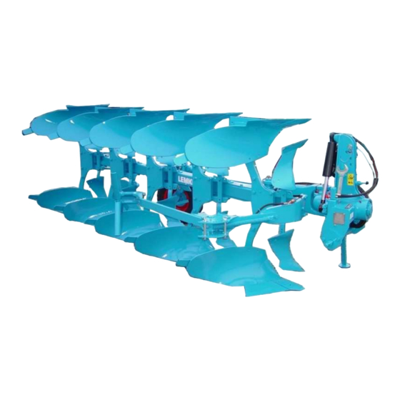
- Page 1 Mounted Reversible Ploughs VariOpal - EN - Item no. 175_1467 5/11.09 LEMKEN GmbH & Co. KG Weseler Straße 5, D-46519 Alpen / PO Box 11 60, D-46515 Alpen Telephone (0 28 02) 81-0, Fax (0 28 02) 81-220 E-mail: lemken@lemken.com, Internet: http://www.lemken.com...
- Page 3 However, this brief instruction is not a substitute for thorough study of the operating instructions. These operating instructions will help to familiarise you with the LEMKEN GmbH & Co. KG device and the options available for using it.
- Page 4 Remember that you should only use genuine LEMKEN spare parts. Reproduction parts have a negative influence on the function of the device, have a shorter ser- vice life and present risks and hazards that cannot be estimated by LEMKEN GmbH & Co. KG. They also increase the maintenance costs.
-
Page 5: Table Of Contents
VariOpal (X, HX) – Manual hydraulic plough control system........15 3.6.2 VariOpal OF (X) – Manual hydraulic plough control system........15 3.6.3 VariOpal (X, HX) – EPS electronic plough control system ........16 Axle Loads ........................17 Use..........................18 General Instructions ....................18 Top Link Connection.................... - Page 6 Attaching and Detaching the Plough ..............24 Attaching........................24 Detaching........................25 Turning the Plough Frame ..................27 Onland-Use (VariOpal OF) ..................29 General Instructions ....................29 Conversion from F-Operation to O-Operation ............29 Converison from O-Operation to F-Operation ............30 Adjustment Centre Optiquick..................
- Page 7 Contents 8.7.2 Angle Adjustment ..................... 43 8.7.3 Working Depth ......................43 8.7.4 Conversion to the front or rear ................. 44 8.7.5 Tail pieces (for D1 and M2, only) ................44 Trashboard........................45 Sword Coulter......................45 8.10 Disc Coulters ....................... 46 8.10.1 General Instructions .....................
- Page 8 Contents 12 Trouble Shooting ....................64 12.1 Hydraulic Equipment ....................64 12.2 Penetration and Depth Guidance of the Plough, Slippage ........66 12.3 Others........................... 67 13 Transport on Public Roads ..................68 13.1 Laws and regulations....................68 13.2 Warning Boards and Lighting Equipment..............68 13.3 Transport Speed......................
-
Page 9: Safety Instructions
Safety Instructions SAFETY INSTRUCTIONS General Safety Instructions • Before using the machine, always check both it and the tractor for roadworthi- ness and operational safety! • As well as the notes in these instructions the operator is advised to comply with the generally applicable safety at work regulations and those relating to use of the public highway! •... - Page 10 Safety Instructions • Fit and check transport gear, road lights and warning guards! • The release ropes for quick coupler latches should hang freely and in the low- ered position must not release the quick coupling by themselves. • Never leave the driver's seat whilst in motion! •...
- Page 11 • Regularly check the hydraulic pipes and replace them in the event of damage or signs of ageing. The replacement pipes must comply with the technical specification as laid down by Lemken! • When searching for leaks appropriate aids should be used because of the dan- ger of injury! •...
- Page 12 Safety Instructions Tyres • When working on the tyres make sure that the implement has been placed on the ground safely and that it is secured by chocks against unintentional rolling! • Fitting tyres requires knowledge and special tools! Repair work on tyres may only be conducted by trained staff and with suitable •...
-
Page 13: Warning Stickers
WARNING STICKERS General Instructions The LEMKEN implement is equipped with all features to ensure safe operation. Where potential danger areas of the implement can not be fully safeguarded, warning stickers are fitted which draw attention to these. Damaged, lost or un- readable warning stickers must be replaced immediately. - Page 14 Warning Stickers WARNING: Pinch point! WARNING: Keep well clear of the turning and swinging area of the implement! 390 0520 WARNING: Hydraulic accumulator contains gas and oil under pressure. For removal and repair instructions in technical manual must be followed! 390 0591...
-
Page 15: Position Of The Warning Stickers
Warning Stickers Position of the Warning Stickers... -
Page 16: Preparation Of The Tractor
Preparation of the Tractor PREPARATION OF THE TRACTOR Tyres The pressure - especially in the rear tractor tyres - must be equal. In heavy condi- tions it may be necessary to add wheel weights and/or water ballast. (See manu- facturer’s instructions). Lift Rods Adjust lift rods to equal length. -
Page 17: Variopal (X, Hx) - Manual Hydraulic Plough Control System
Preparation of the Tractor 3.6.1 VariOpal (X, HX) – Manual hydraulic plough control system Required control units Single-acting Double-acting Double-acting connection Slewing cylinder Single-acting with return connection to oil tank* / ** With Vari Stop** With Vari Stop plus With hydraulic tilt adjustment... -
Page 18: Variopal (X, Hx) - Eps Electronic Plough Control System
Preparation of the Tractor 3.6.3 VariOpal (X, HX) – EPS electronic plough control system Required control units or hydraulic systems Hydraulic overload protection Double-acting control unit Combination block for actuating all other hydrau- Load sensing system with pressure, return lic cylinders incl. hydraulic front-furrow width ad-... -
Page 19: Axle Loads
Preparation of the Tractor Axle Loads The attachment of implements to the front- and rear-three point linkage must not lead to exceeding the allowed total weight, the allowed axle load and the allowed tyre load of the tractor. The tractor front axle must always be loaded with 20 % of the tractor dead weight at minimum. -
Page 20: Use
General Instructions Before the first use it is recommendable - with fully lowered implement - to carry out the following adjustments at the farm. Afterwards only few adjustment correc- tions have to be carried out in the field. Top Link Connection Connect top link to headstock (1) and en- sure that the top link rises slightly towards the plough. -
Page 21: Adjustment Of The Outer Turnbuckle Of The Adjustment Centre Optiquick
Adjustment of the outer Turnbuckle of the Adjustment Centre Op- tiquick The outer turnbuckle (2) has been adjusted to the extreme to allow compact transport on lorries. Adjust this turnbuckle to a length similar to that of the main link (3). Final ad- justments can take place in the field. -
Page 22: Clearance For The Turnover Operation
Clearance for the Turnover Operation Check whether there is sufficient clearance between plough/depth wheel and ground. If not, shorten the inner turnbuckle (1), set drawbar deeper, fit top link to a higher hole in the headstock or use an hydraulic frame swing-in assy. -
Page 23: On The Field
On the Field Set tractor hydraulics to ‘Draft Control’ or 'Mixed Control'. Set in the plough and adjust the length of the top link, vertical pitch, front furrow width, working depth and depth control wheel / depth and transport wheel as re- quired. -
Page 24: General Information
Three Point Attachment 4.9.1 General information Loss of the implement The tractor's three-point linkage category and the category of the WARNING draw rail and top link pin must match. Otherwise, the draw rail and the top link pin may slip out of the linkage when driving over un- even ground or due to vibrations. -
Page 25: Height Adjustment Of The Drawbar
4.9.2 Height Adjustment of the Drawbar The drawbar (1) can be set in two different heigth positions. Fundamentally the top position should be chosen to reach a better entry of the implement. The lower position should be chosen, only when the implement cannot lifted sufficiently turning... -
Page 26: Attaching And Detaching The Plough
− Swing stand upwards and move in by approximately 30 cm! (It may not touch the turnover mechanism during turning operation.) Not required with VariOpal − Ensure that the securing pin (3) is lo- cked! − Push stand with spring clamp (4) above the spindle or with the OF-version abo- ve the outer hydraulic ram and secure! −... -
Page 27: Detaching
Attaching and Detaching the Plough Detaching − Park the plough on a firm and level ground! − Turn plough to working position! − Set tractor hydraulics to ‘Position Con- trol’! − Lower plough completely! − Make hydraulic hoses pressureless! See operating manual of the tractors manufacturer! −... - Page 28 Attaching and Detaching the Plough Read and adhere to the General Safety Instructions as well as to the Instructions ’Mounted implements’!
-
Page 29: Turning The Plough Frame
Turning the Plough Frame TURNING THE PLOUGH FRAME The turnover device is equipped with a double acting turnover ram (1) with auto- matic turnover valve and automatic lock valve for the connection to a double acting spool valve. In combination with a separate return pipe to the oil tank of the tractor it is possible to connect the turnover ram to a single acting tractor spool valve. - Page 30 Turning the Plough Frame − For the turning operation raise plough completly! − Switch control lever to "H": Plough frame turns through about 180° ! − After completion of the turnover opera- tion move the lever to the position ‘N’. After 3 - 6 seconds the next turnover can be started.
-
Page 31: Onland-Use (Variopal Of)
F-operation = use in the furrow behind a tractor Contrary to the VariOpal the VariOpal OF shows the adjustment centre Optiquick with a long main link (1), a hydraulic ram (2) and a hydraulic ram (3) with lock valve (4) for the frame swing-in procedure. -
Page 32: Converison From O-Operation To F-Operation
Onland-Use (VariOpal OF) Converison from O-Operation to F-Operation For the conversion from working onland (O-operation) to working in the furrow (F- operation) the hydraulic ram (2) must be opened. After that the lock valve (4) must be opened to activate the frame swing-in as- sembly. -
Page 33: Adjustment Centre Optiquick
Onland-Use (VariOpal OF) Adjustment Centre Optiquick 7.4.1 F-Operation Front Furrow Width Adjustment Before adjustment, open the hydraulic ram (1) a little to unload the adjuster sleeve (2). This will be done by lowering the plough fully and pressurising the port ‘P’ of the turnover ram briefly. - Page 34 Onland-Use (VariOpal OF) Correction of the Lateral Draw respec- tively Adjustment of the Tractor/Plough Alignment Operate the inner hydraulic ram (1) to ad- just the tractor/plough alignment. If the tractor pulls to the ploughed land => open inner hydraulic ram (1) slightly If the tractor pulls to the unploughed land =>...
-
Page 35: O-Operation
Onland-Use (VariOpal OF) 7.4.2 O-Operation Distance from the Tractor to the Furrow Wall The distance of the tractor to the furrow wall will be adjusted by means of the inner hydraulic ram (1). Distance too narrow => close hydraulic ram (1) slightly Distance too wide =>... -
Page 36: Adjustments
Adjustments ADJUSTMENTS • Read and adhere to the General Safety Instructions! • The implement may only be operated, maintained and repaired by such persons who have been made acquainted with it and who have been advised about the dangers! Adjustment- maintenance operations well... -
Page 37: Tractor/Plough Alignment
Adjustments Tractor/Plough Alignment Adjust the tractor/plough alignment by means of the inner turnbuckle (2), so that there is no lateral draw. Tractor pulls to the ploughed land => lengthen inner turnbuckle (2)! Tractor pulls to the unploughed land => shorten inner turnbuckle (2)! It is always positive to adjust the inner turnbuckle as short as possible (saving of turning energy, low oil heating, higher lift height, lower landslide wear and lower tractive-force requirement). -
Page 38: Angular Adjustment
Adjustments Angular adjustment 8.3.1 General information When ploughing, the base blade should be almost vertical to the ground as seen from the direction of travel. If this is not the case, then the angular adjustment must be altered as described below. 8.3.2 Angular adjustment (double acting) a) Raise plough by several centimetres (approx. -
Page 39: Angular Adjustment (Single Acting)
Adjustments 8.3.3 Angular adjustment (single acting) In combination with a slewing cylinder (1) connected to a single-acting control unit with a return line to the tractor's oil tank, the angular adjustment is set as mentioned in points a) - c) of the previous section. Following this raise the plough completely, turn it all the way and then back again after approx. -
Page 40: Working Depth
Adjustments • Risk of crushing and shearing in the area between the stopper arm and the end stop! Keep to a sufficient safety distance! Working Depth The working depth adjustment occurs via the tractor hydraulics and the depth wheel of the plough. The instructions for the adjustment of the tractor hydraulics can be learned from the operating manual of the tractor manufacturer. -
Page 41: Hydraulic Frame Swing-In Assembly - Memory Ram
Adjustments Hydraulic Frame Swing-in Assembly - Memory ram The Memory ram is connected via 2 hoses to the turnover ram and via 2 further hoses with a separate double acting tractor spool valve. Independently it is possible with the Memory ram to (1) −... -
Page 42: Plough Body Adjustments
Adjustments Plough Body Adjustments 8.6.1 Pitch The distance A between point and plough frame should be the same with all plough bodies. The measurement D should be 1,5 Required settings will be done by means of the set screws (1). Therefore slacken bolts (2) and clamp screws (3). -
Page 43: Working Width Per Body
Adjustments 8.6.2 Working Width per Body After the basic adjustment has been car- ried through by means of the OPTIQUICK- adjustment (Trulign), the working width per body can be adjusted from the tractor seat by means of a Memory ram (1) or an ad- juster ram (2). -
Page 44: Tail Pieces
Adjustments 8.6.3 Tail Pieces The tail pieces (2) being positioned at the end of the mouldboards (1) should be ad- justed so that they help to turn the furrow slice. They should be adjusted uniformly. Set too deeply, they can cause soil to fall back into the furrow. -
Page 45: Angle Adjustment
Adjustments 8.7.2 Angle Adjustment The angle of the skimmers which are fitted with their flat stalk (4) directly to the stalk bracket (5) or the beam of the X-ploughs, cannot be changed. Otherwise the angle is adjustable either − − − − variably by means of clamp screws with the skimmers with round stalk or −... -
Page 46: Conversion To The Front Or Rear
Adjustments 8.7.4 Conversion to the front or rear By means of re-positioning the skim stalk (4) or the bracket of the angle adjustment to the front or rear, the position of the skimmer (1) can be optimised. To the rear = more clearance between skimmer and the plough body fitted in front. -
Page 47: Trashboard
Adjustments Trashboard Fit trashboard (1) with holder (2) to the mouldboard (3). The holder is provided with slotted holes (6) which allow an uni- versal adjustment. Adjust support-bolt (4) so that it touches the leg. Secure support-bolt (4) by means of the counter nut (5). -
Page 48: Disc Coulters
Adjustments 8.10 Disc Coulters 8.10.1 General Instructions When fitted, disc coulters should be set to a working depth of 7 - 9 cm and 2 - 3 cm to the landslide of the body. With the X- ploughs the disc coulter will be fitted to the beam by means of the holder and bolts (1). -
Page 49: Swivelling Limitation
Adjustments 8.10.4 Swivelling limitation By means of the adjustable stop (9) the lateral swivelling range of the disc coulter will be adjusted. IMPORTANT: All slackened bolts and nuts must be tightened carefully after adjustment. Never drive backwards with the plough when the disc coul- ters are still in the ground. -
Page 50: Soil Looseners
Adjustments 8.12 Soil Looseners 8.12.1 Subsoilers The subsoiler UD6 will be fitted as shown in the sketch. By means of displacing the stalk (1) the working depth of the subsoiler can be adjusted. Maximum working depth = 20 cm Minimum working depth = 14 cm For changing the working depth unsecure pin (2) and remove. -
Page 51: Depth Control Wheel And Depth And Transport Wheel
Adjustments 8.13 Depth Control Wheel and Depth and Transport Wheel 8.13.1 General Instructions The plough is available with depth control wheel (1) or depth and transport wheel. The depth and transport wheel is required when the front axle - especially for trans- port - is unloaded too much and so the steerability of the tractor is no more en- sured. -
Page 52: Air Pressure
Adjustments b) Version with hydraulic adjustment With the hydraulically adjustable depth and transport wheel the working depth can be adjusted in cab via the tractor spool valve. It is recommended after working depth ad- justment to re-adjust beside the length of the top link and the angle adjustment also the tractor draft control, to prevent an in- creased slippage or an insufficient depth... -
Page 53: Converting Uni Wheel From Working Position Into Transport Position
Adjustments 8.13.4 Converting uni wheel from working position into transport position − − − − Detach chain (1) from gear wheel! − − − − For hydraulically-adjustable wheel, detach the hydraulic hoses (2) from the plug and socket connectors (6), plug the protective caps onto the hydrau- lic plug and socket connectors, and then place the hydraulic hoses such that they... -
Page 54: Converting Uni Wheel From Transport Position Into Working Position
Adjustments 8.13.5 Converting uni wheel from transport position into working position − − − − Connect and secure upper link to mast! − − − − Raise plough slightly and swivel locking pin (5) out through approx. 180° . The handle must engage at the front into the recess, to ensure that the locking pin does not slide back again of its own ac-... -
Page 55: Overload Safety Devices
Type of Plough Part No Dimension VariOpal 5 and 6 301 3407 M 12X70 8.8 VariOpal 5 X and 6 X 301 3399 M 12X65 10.9 VariOpal 7 and 8 301 3424 M 12X75 LS 57X15 - 10.9 VariOpal 7 X and 8 X 301 3595 M 14X70 LS 51X15 - 10.9... - Page 56 Overload Safety Devices • There are pinch positions in the area of the shearbolt device! • Do not allow any body within the release area of the bodies! • After a break of the shearbolt, the body releases upwards. Keep distance!
-
Page 57: Semi-Automatic Overload Safety Device Hx
Overload Safety Devices Semi-Automatic Overload Safety Device HX The mounted reversible ploughs of the HX- range are equipped with a semi-automatic overload safety device. It is a compact device with hooks (1), roller (2) and springs (3, 4 and 5) located inside the leg bracket (6). -
Page 58: Automatic Non-Stop Overload Safety Device
Overload Safety Devices Automatic Non-Stop Overload Safety Device The overload safety device is set at the factory for average conditions. Should the mechanism still trip without touching an obstacle, the tripping force of the overload safety device must be in- creased. -
Page 59: Adjusting The Operation Pressure
Overload Safety Devices 9.4.1 Adjusting the Operation Pressure After connecting the adjusting valve unit to the tractor spool valve, the system is oper- able with the maximum and minimum op- eration pressures adjusted by the factory. If required the operation pressure can be adapted individually. -
Page 60: Operation
Overload Safety Devices 9.4.2 Operation During work the plough bodies will be kept in working position via the rolling sys- tem. When touching an obstacle the plough body trips upwards, therewith the oil will be led into the hydro-reservoir. If several bodies trip at the same time, the oil cannot be kept by the hydro-reservoir. -
Page 61: Make Hydraulic System Pressureless
Overload Safety Devices 9.4.3 Make hydraulic system pressureless The hydraulic system must always be without pressure, for repair or service work example. Therefore with lowered plough the tractor spool valve must be set to floating position and the relief valve (4) opened. -
Page 62: Attachment Arm
Attachment Arm ATTACHMENT ARM The attachment arm (1) will be fitted to the flange (3) in front of the plough fame (4) by means of the bracket (2). See operating manual of the attachment arm. Attention! In combination with tractors having a long hydraulic pipe between spool valve and hydraulic coupling, an hydro reservoir (5) is required for the hydraulic assembly of the... -
Page 63: Maintenance
Maintenance MAINTENANCE All lubrication points must be greased regularly with environmentally friendly grease according to the following table. For a long operation break the piston rods of the hydraulic rams must be greased with non-acid grease. The polished areas of wearing parts and the pins as well as adjusting devices must be treated with grease regularly. - Page 64 Tightening torque 450 Nm − − − − At least 6 years after the date stated on the high pressure hose the high pres- sure hoses must be replaced against genuine LEMKEN-hoses. Porous or de- fective high pressure hoses must be replaced immediately.
- Page 65 Maintenance • Read and adhere to the General Safety Instructions as well as to the instructions ‘Maintenance‘!
-
Page 66: Trouble Shooting
Trouble Shooting TROUBLE SHOOTING 12.1 Hydraulic Equipment Malfunction Reason Remedy The plough frame starts turning The friction of the Grease pivot bolts care- before Memory ram is swung-in frame pivot bolts is fully, and that according completely. too high to the maintenance table. Memory ram does not open or The throttle bores of Screw out the threaded... - Page 67 Trouble Shooting Malfunction Reason Remedy Plough frame turns up to the mid- The required switch- a) By means of removing dle position and stops. over pressure for the the washers (U) the turnover ram has not pre-adjusted switch- been reached by the over pressure will be tractor hydraulics.
-
Page 68: Penetration And Depth Guidance Of The Plough, Slippage
Trouble Shooting Malfunction Reason Remedy Front furrow width changes during The piston seal of Replace the piston seal work. the swing-in ram or Memory ram is leaky. 12.2 Penetration and Depth Guidance of the Plough, Slippage Malfunction Reason Remedy a) Increase distance Plough does not stay in the a) Penetration force too low... -
Page 69: Others
Trouble Shooting 12.3 Others Malfunction Reason Remedy Shearbolt of the body Incorrect shearbolt is fitted. Use original shearbolts. Fit shears often. the shearbolts from the fur- row side of the plough. -
Page 70: Transport On Public Roads
Transport on Public Roads TRANSPORT ON PUBLIC ROADS 13.1 Laws and regulations All laws and regulations with regard to transport on public roads must be adhered 13.2 Warning Boards and Lighting Equipment If it is required to drive on public roads with the plough fitted to the tractor, fit warn- ing boards and lighting equipment. -
Page 71: Technical Data
No. Of furrows PS 70 80 90 100 110 120 130 150 160 180 190 200 210 VariOpal 5 (X, HX) VariOpal 6 (X, HX) VariOpal 7 (X, HX) VariOpal 8 (X) VariOpal 9 (X) The table shows the allowed range of power applying to the type of plough and the number of furrows. -
Page 72: Weight
Technical data 14.3 Weight VariOpal 2-furrows 3-furrows 4-furrows 5-furrows 6-furrows 1078 1276 1134 1382 1139 1412 1666 1910 1257 1553 1805 2067 1176 1306 1561 1053 1386 1707 1331 1668 1986 2267 1464 1829 2150 Weight in kg (2- to 4-furrows with depth wheel, from 5-furrows on with depth and transport wheel). -
Page 73: Noise, Airborne Sound
Noise, Airborne Sound NOISE, AIRBORNE SOUND The noise level of the implement does not exceed 70 dB (A) during work. NOTES As the version of equipment is depending from the order, the equipment of your implement and its description concerned may deviate in some cases. To ensure a continuously updating of the technical features, we reserve the right to modify the design, equipment and technique. -
Page 74: Index
INDEX Air Pressure ......................50 Allowed Range of Power ..................69 Angular adjustment ..................... 36 Attaching ......................24 ATTACHMENT ARM................... 60 Automatic Non-Stop Overload Safety Device ............56 Axle Loads ......................17 Check Chains...................... 14 Depth and Transport Wheel ................49 Depth Control Wheel ................... - Page 75 Index Soil Looseners ....................48 Subsoiler ......................48 Subsoiler Shares....................48 Sway Blocks......................14 Sword Coulter ..................... 45 Tail Pieces ....................42, 44 Three Point Attachment..................22 Top Link ......................14 Top Link Connection ................... 18 Transport......................68 Trashboard......................45 Use ........................
Need help?
Do you have a question about the VariOpal and is the answer not in the manual?
Questions and answers