Table of Contents
Advertisement
Quick Links
Advertisement
Table of Contents

Related Manuals for LEMKEN Diamant 12 V


Summary of Contents for LEMKEN Diamant 12 V
- Page 1 Operating Instructions Semi-Mounted Reversible Ploughs Diamant 12 V - en - Item no. 17510894 1/02.13 LEMKEN GmbH & Co. KG Weseler Straße 5, 46519 Alpen / Germany Telephone +49 28 02 81 0, Fax +49 28 02 81 220 lemken@lemken.com, www.LEMKEN.com...
- Page 3 However, this brief instruction is not a substitute for thorough study of the operating instructions. These operating instructions will help to familiarise you with the LEMKEN GmbH & Co. KG device and the options available for using it.
- Page 4 Remember that you should only use genuine LEMKEN spare parts. Reproduction parts have a negative influence on the function of the device, have a shorter ser- vice life and present risks and hazards that cannot be estimated by LEMKEN GmbH & Co. KG. They also increase the maintenance costs.
-
Page 5: Table Of Contents
Contents CONTENTS Contents ........................... 3 General information ....................8 Liability ........................... 8 Guarantee ........................8 Copyright ........................9 Optional accessories ....................9 Symbols used in the Operating Instructions ............10 ... - Page 6 Contents 3.9.2 Requirements of the tractor ..................21 3.9.3 Axle loads ........................22 3.9.4 Check before departure ..................... 26 3.9.5 Correct behaviour in road traffic ................27 3.10 Obligation of the operator ..................27 ...
- Page 7 Contents Preparing the implement ..................41 Stand length ......................... 41 Removing the lighting equipment ................42 Attaching the implement ..................44 Specific safety information ..................44 Brake system ....................... 46 ...
- Page 8 Contents 12.10 DuraMaxx plough body ....................68 12.10.1 Contact angle ...................... 68 12.11 Landside........................69 12.12 Skimmer ........................70 12.12.1 General information ..................... 70 12.12.2 Adjustment of the projection angle ..............70 ...
- Page 9 Contents 15.1.3 Immobilise the implement for maintenance and repairs ......... 86 15.1.4 Working on the hydraulics ..................86 15.1.5 Personnel qualifications ..................86 15.1.6 Protective equipment ....................87 15.1.7 Utilised tool ......................87 ...
-
Page 10: General Information
Co. KG, in particular Section IX, shall apply. Liability. In line with the dimensions cited in these conditions the LEMKEN GmbH & Co. KG shall not be held liable for any personal or material damage, when such damage is caused by one or more of the following reasons: ... -
Page 11: Copyright
Infringements will result in a claim for damages. Optional accessories LEMKEN implements may be equipped with various accessories. The operating instructions below describe both series components and optional accessories. Please note: These accessories will vary depending on the type of equipment. -
Page 12: Symbols Used In The Operating Instructions
Symbols used in the Operating Instructions SYMBOLS USED IN THE OPERATING INSTRUCTIONS Hazard classes The following symbols are used in the Operating Instructions for particularly im- portant information: DANGER Denotes an imminent hazard with high risk, which will result in death or severe physical injury, if not avoided. -
Page 13: Indication Of Passages
Symbols used in the Operating Instructions Indication of passages The following symbols are used for particular passages in the operating instruc- tions: Indicates work steps Indicates enumerations... -
Page 14: Safety Measures And Precautions
Safety measures and precautions SAFETY MEASURES AND PRECAUTIONS General safety instructions for the operator are specified in the chapter entitled «Safety measures and precautions». At the start of some main chapters the safety instructions, which refer to all work to be carried out in this chapter, are listed to- gether. -
Page 15: Safety Features Of The Device
Safety measures and precautions Safety features of the device To protect the operator and the device, the device is equipped with special safety features in accordance with country specific requirements. Always keep all safety devices in working order. Safety and warning signs 3.4.1 General information The implement features all equipment which ensures safe operation. -
Page 16: Overview Of The Position Of Warning Symbols
Safety measures and precautions 3.4.2 Overview of the position of warning symbols... -
Page 17: Meaning Of Warning Signs
Safety measures and precautions 3.4.3 Meaning of warning signs Please familiarise yourself with the meaning of the warning signs. The following explanations provide detailed information. Please read and observe the operating in- structions and safety instructions before starting up the implement for the first time. Before carrying out maintenance or repair work, switch off the engine and remove key. -
Page 18: Meaning Of Other Symbols
Safety measures and precautions Keep well clear of the turning and swinging area of the implement. Hydraulic accumulator contains gas and oil under pressure. For removal and repair instructions in technical manual must be followed. 3.4.4 Meaning of other symbols. Do not clean with high-pressure cleaner. -
Page 19: Special Safety Instructions
Safety measures and precautions Special safety instructions Risk of injury due to non-observance of the currently valid occupational safety guidelines If the currently valid occupational safety guidelines are bypassed WARNING or safety equipment is rendered unusable when handling the de- vice, there is a risk of injury. - Page 20 Safety measures and precautions Risk of injury when freeing casualties When rescuing people trapped or injured by the device, there is a risk of additional serious injury to the casualty if the hydraulic con- nections were not connected according to their colour coding as described in the section entitled "Required hydraulic equipment".
-
Page 21: Danger Areas
Safety measures and precautions Danger areas Moving danger area WARNING The danger area of the implement moves with the implement dur- ing operation. While the implement is being operated, persons are not permitted in front of the actual danger area because the danger area moves with the implement. -
Page 22: Hazard Caused By Mechanical Systems
Safety measures and precautions 3.7.1 Hazard caused by mechanical systems There is a risk of accidents due to crushing, cutting and striking body parts on abruptly moving machine parts, on moving machine parts caused by stored mechanical energy in elastic parts, such as springs, ... -
Page 23: Operation On Public Highways
Safety measures and precautions Operation on public highways 3.9.1 Lighting system and identification A proper lighting system, identification and equipment must be on the device if it is to be transported on public roads. Further information can be requested from the appropriate authorities. -
Page 24: Axle Loads
Safety measures and precautions 3.9.3 Axle loads Implements mounted to the front and rear three-point linkage must not result in the following being exceeded: permissible gross weight of tractor, permissible axle loads of tractor, the tractor's tyre load-carrying capacities. The tractor's front axle must always be loaded with at least 20 % of the tractor's curb weight. - Page 25 Safety measures and precautions Data from tractor operating instructions Take the following data from your tractor's operating instructions: Abbreviation Data Tractor kerb weight (kg) _______ kg Front axle load (kg) of empty tractor _______ kg Rear axle load (kg) of empty tractor _______ kg Data from implement operating instructions ...
- Page 26 Safety measures and precautions Calculation of minimum ballasting value at front G for rear mounting V min implement x (c + d) – T x b + (0.2 x T x b) V min a + b Enter the calculated minimum ballasting value, as required at the front of the tractor, into the table.
- Page 27 Safety measures and precautions Calculation of actual rear axle load T H tat H tat V tat Enter the value for the calculated actual rear axle load and the permissible rear axle load as given in the tractor's operating instructions into the table. Tyre load-carrying capacity ...
-
Page 28: Check Before Departure
Safety measures and precautions 3.9.4 Check before departure Check that the implement's brakes are working properly before driving off. Before driving with the implement raised, lock the control lever to prevent it from dropping down; otherwise the implement may be lowered unintentionally. ... -
Page 29: Correct Behaviour In Road Traffic
Safety measures and precautions 3.9.5 Correct behaviour in road traffic When driving on public highways, observe the relevant statutory national regu- lations. Driving behaviour, steering and braking performance are influenced by ballast weights. Ensure that the tractor has adequate steering and braking performance. ... -
Page 30: Operating The Device Safely
Safety measures and precautions 3.11 Operating the device safely 3.11.1 General information Before starting work, familiarise yourself with all equipment and actuating ele- ments as well as their functions. Do not operate the device until all protective devices have been attached and are in the safety position. -
Page 31: Personnel Selection And Qualifications
Safety measures and precautions 3.11.2 Personnel selection and qualifications The driver of the tractor must have the appropriate driving licence. Any work on the device may be carried out by trained and instructed personnel only. Personnel must not be on drugs, intoxicated or taking medication. ... -
Page 32: Handing Over The Device
Handing over the device HANDING OVER THE DEVICE As soon as the device is delivered, ensure that it corresponds with the order package. Also check the type and completeness of any supplied accessories. When the device is handed over, your dealer will explain how it works. ... -
Page 33: Layout And Description
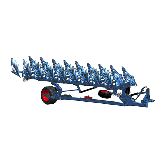
Layout and description LAYOUT AND DESCRIPTION Overview 1 Cross shaft (headstock) 6 Wheel 2 Hydraulic ram for traction increase device 7 Frame 3 Turnover ram 8 Plough body 4 Depth control wheel 9 Pre-ploughing tools - not shown 5 Stabiliser Description 5.2.1 Drawbar The three-point linkage with upper link pin and drawbar corresponds to ISO 730. -
Page 34: Turnover Ram
Layout and description 5.2.3 Turnover ram The implement is turned over smoothly by two hydraulic rams (3). 5.2.4 Depth control wheel During the turning process, the depth con- trol wheel swivels into the opposite working position as a result of gravity. 5.2.5 Stabiliser The stabiliser (4) guides the wheel as well as supporting and pulling the frame. -
Page 35: Land Wheel
Layout and description 5.2.6 Land wheel Large deep-tread land wheel for low ground pressure when ploughing. 5.2.7 Frame Working width can be continuously adjust- ed hydraulically... -
Page 36: Plough Body
Layout and description 5.2.8 Plough body DuraMaxx The mould boards (1) or slats (2) are at- tached to the body (4) with hooks (3). This means that they can changed without hav- ing to use tools. This cuts the time required by up to 80%. - Page 37 Layout and description Skimmer (2) Coulter (3) Disc coulter (4)
-
Page 38: Preparation Of The Tractor
Preparation of the Tractor PREPARATION OF THE TRACTOR Tyres The pressure - especially in the rear tractor tyres - must be equal. In heavy condi- tions it may be necessary to add wheel weights and/or water ballast. (See manu- facturer’s instructions). Lift Rods Adjust lift rods to equal length. -
Page 39: Hydraulic Equipment Required
Preparation of the Tractor Hydraulic equipment required The implement is supplied as standard with separate hydraulic connections for each consumer. The protecting caps on the hydraulic connections are coloured and the hydraulic connections themselves are marked alphanumerically. In order to activate the individual hydraulic devices listed below, the tractor must be equipped with the following spool valves: Spool valves or hydraulic systems required... -
Page 40: Required Sockets
Preparation of the Tractor Required Sockets For the electric use of the implement the following sources of electricity must be available at the tractor: Direct connection to Voltage Socket the tractor battery Electronic Control according to Lighting Equipment DIN-ISO 1724... -
Page 41: Power Supply
Preparation of the Tractor Power supply A supply voltage of 12 V is required for the electronic control system. Over- and undervoltages cause malfunctions and may destroy the electrical equipment. After mounting the implement on the trac- tor, connect the cable for the electronic control system as follows: ... -
Page 42: Exterior Width Of The Tractor
Preparation of the Tractor Exterior width of the tractor The maximum permissible exterior width of the tractor must not exceed 300 cm. If this dimension is exceeded, the extent to which the tractor can steer into the im- plement is restricted. CAUTION Risk of collision and damage When steering the tractor in, the tyres or parts of the tractor must... -
Page 43: Preparing The Implement
Preparing the implement PREPARING THE IMPLEMENT Stand length The length of the stand (6) must be adjust- ed so that the cross shaft is parallel to the ground when the implement is parked in the working position. See «Stands, page 50». -
Page 44: Removing The Lighting Equipment
Preparing the implement Removing the lighting equipment The lighting equipment must be removed before the implement is used in the field, as follows: Remove the plug (5) for the lighting equipment. Option 1 Option 2 Remove the linch pins (4) on the left and right sides. - Page 45 Preparing the implement Roll up the cable (3) towards the rear. Remove the lighting carrier (2). Option 1 Option 2...
-
Page 46: Attaching The Implement
Attaching the implement ATTACHING THE IMPLEMENT Specific safety information Risk of injury when attaching the implement There is a risk of body parts getting trapped and crushed between tractor and implement. The three-point linkage has a ball joint and, when used in conjunction with the traction increase unit, is also connected to the drawbar via a hydraulic cylinder. - Page 47 Attaching the implement Risk of injury due to unsecured upper link pin If the upper link pin is not secured, it may slide out or get lost. Possible consequences: DANGER The implement could fall down or sustain damage Persons in the direct vicinity could be injured The upper link pin must be secured at all times.
-
Page 48: Brake System
Attaching the implement Brake system Implements without a brake system may only be operated with tractors which have sufficient braking effect under all conditions. Depending on national regulations, a safety chain may be re- quired for the operation of the implement without a brake system. The safety chain must be replaced if the implement becomes detached and strain is placed on the safety chain Implements without a brake system, or with a defective brake system may only be... -
Page 49: General
Attaching the implement General When attaching the implement, switch the hydraulic system for the tractor's three-point linkage to position control. Connect the lower links of the tractor to the cross shaft (1). Fix the lower links at the sides using check chains or stabilisers. - Page 50 Attaching the implement Pull the handle on the spring-loaded locking pin (5) in the stand (6) to unlock the stand. Pivot the stand (6) upwards. Secure the stand (6) with the locking pin (5). The locking pin (5) must snap into place in the hole (7).
- Page 51 Attaching the implement Pivot the stand (8) upwards. Place the stand (8) in the holder (9). Install the warning boards and/or lighting equipment if the plough will be trans- ported on public roads. See «travelling on public roads, page 53». ...
-
Page 52: Stands
Attaching the implement Stands The length of the stand (6) must be adjust- ed so that the cross shaft (1) is parallel to the ground when the implement is parked in the working position. After mounting the implement on the trac- tor: ... -
Page 53: Uncoupling The Implement
Uncoupling the implement UNCOUPLING THE IMPLEMENT Specific safety information Risk of injury when removing the implement There is a risk of crushing body parts between the tractor and im- plement. The headstock is connected with the drawbar by a ball joint and the hydraulic ram for the traction increase device. - Page 54 Uncoupling the implement Turn the frame into the working position. Lower the frame. Switch off the tractor engine. Depressurise the tractor hydraulic sys- tem. See the tractor manufacturer's op- erating instructions. Disconnect the hydraulic hoses. ...
-
Page 55: Driving On Public Roads
Driving on public roads DRIVING ON PUBLIC ROADS 10.1 General The following preparations must be made before travelling on public roads: Turn the frame (1) to the half-turned po- sition = middle position. Install the lighting equipment (2). See «lighting equipment, page 54». -
Page 56: Installing The Lighting Equipment
Driving on public roads 10.2 Installing the lighting equipment Install the lighting carriers (2) as shown, according to the version supplied. Unroll the cable (3) towards the front. Insert the linch pins (4) on the left and right sides. - Page 57 Driving on public roads Connect the lighting equipment using the plug (5), according to the version sup- plied. Option 1 Option 2 Check that the lighting equipment is working.
-
Page 58: Damper On Land Wheel
Driving on public roads 10.3 Damper on land wheel During in-furrow ploughing in the field, the damper (1) does not function, as the bracket (2) is resting on the pin (3) for depth limitation. When travelling on the headland and on the road, the pin (3) for depth limitation must be able to move freely. -
Page 59: Turncontrol Electronic Control System
TurnControl electronic control system TURNCONTROL ELECTRONIC CONTROL SYSTEM The following functions are carried out during operation using the operating termi- nal: Inclination adjustment - see «Inclination, page 66». The display at top right shows the current position Save the inclination selected ... -
Page 60: Operation
Operation OPERATION 12.1 Specific safety information Read and observe the "Safety measures and precautions" sec- tion. CAUTION This implement should always be used, operated and repaired by persons who are familiar with it and aware of the risks. ... -
Page 61: Turning The Frame
Operation 12.2 Turning the frame Ensure that the general health and safety precautions are tak- en, see page 12. DANGER Before turning the frame, always check that there is no one in the turning and pivoting range of the plough. ... -
Page 62: Turning On The Headland
Operation 12.3 Turning on the headland DANGER Risk of damage to components If an implement is not raised all the way, there is a risk of damage to components if the tractor is not turned correctly at the headland. Before turning at the headland, the implement must be raised all the way before cornering in order to prevent damage to the implement. -
Page 63: Damper On Land Wheel
Operation 12.4 Damper on land wheel During in-furrow ploughing in the field, the damper (1) does not function, as the bracket (2) is resting on the pin (3) for depth limitation. When travelling on the headland and on the road, the pin (3) for depth limitation must be able to move freely. -
Page 64: Adjusting The System Pressure Of The Traction Increase Device
Operation 12.5 Adjusting the system pressure of the traction increase device If the system pressure of the traction in- crease device has dropped too low, it must be increased. The system pressure can only be checked when the implement is mounted on the tractor. -
Page 65: Setting The Front Furrow Width
Operation 12.6 Setting the front furrow width The front furrow width must be set so that it corresponds to the working width of the following plough bodies. Press this key on the operating terminal (1). The LED lights up (2). ... -
Page 66: Working Width Per Plough Body
Operation 12.7 Working width per plough body The working width is continuously adjusta- ble. Adjustment range: 30 - 55 cm per body. Press this key on the operating terminal (1). The LED (2) lights up. During ploughing, you can set the work- ing width required via the spool valve. - Page 67 Operation Remove the safety device with grip ring from the socket pin (1) on the frame side. Insert the socket pin (1) into the appro- priate hole in the adjustment plates (2) to give the working depth required. ...
-
Page 68: Inclination
Operation 12.8.1 Inclination When the plough is operating, the legs should be almost perpendicular to the ground when viewed in the direction of travel. A uniform ploughed surface is pro- duced when the inclination is set correctly. The inclination is set using the spool valve which is also used for turning. See «required, page 37». -
Page 69: Lateral Force
Operation The value selected flashes in the dis- play (3), you will hear a beep and the operating terminal automatically switch- es to turning mode. The saved inclination is automatically restored after each turning process. Set the inclination without saving ... -
Page 70: Duramaxx Plough Body
Operation 12.10 DuraMaxx plough body 12.10.1 Contact angle The bodies are mounted with the contact angle central to the ground. The notch (3) points forward. The contact angle can be changed with the eccentric screw (1) if re- quired. Release the nuts (2). ... -
Page 71: Landside
Operation 12.11 Landside To achieve better control on a slope, the landside (1) can be set to a lower position. Undo the screw Remove the screw (2). Set the landside (1) to its lowest posi- tion. Replace the screw (2). Standard assembly ... -
Page 72: Skimmer
Operation 12.12 Skimmer 12.12.1 General information The skimmers should work at a depth of around 5 - 10 cm. If you want to plough at a depth of 25 cm, for example, the skim- mers should be adjusted so that the rele- vant share tip on the skimmer is at a dis- tance A of around 15-20 cm from the share tip on the plough base. -
Page 73: Working Depth
Operation 12.12.3 Working depth Risk of crushing CAUTION When setting the working depth, the skimmer may drop down when the pin (4) is removed. Hold on to the skimmer with one hand until you have secured it by inserting the pin. Adjusting the working depth does not change the projection angle setting. -
Page 74: Turning Forwards Or Backwards
Operation 12.12.4 Turning forwards or backwards The position of the skimmer (1) can be op- timised by turning the fertiliser depositor blade (6) forwards or backwards. Backwards = More clearance between skimmer and plough base in front. Forwards = More clearance between skimmer and associated plough body (e.g. -
Page 75: Trashboard
Operation 12.13 Trashboard Screw the trashboard (1) and retainer (2) onto the base blade (3). The retainer (2) has slots (4) to allow uni- versal adjustment. -
Page 76: Landside Coulter
Operation 12.14 Landside coulter Remove the landside wedge (1) before retrofitting the landside coulter. Screw on the landside coulter (2) before the landside (3). Tighten screws again. «Tightening torques, Seite 89». -
Page 77: Disc Coulters
Operation 12.15 Disc coulters 12.15.1 General The disc coulters are designed to work at a depth of approx. 7 - 9 cm and run about 2 - 3 cm to the side of the vertical slat edge. 12.15.2 Working depth To set the working depth of the disc coul- ter, proceed as follows: ... -
Page 78: Clearance To The Side
Operation 12.15.3 Clearance to the side The clearance between the side of the coulter (6) and the edge of the slat is set pivoting the stalk (7) or moving the pin in the oblong hole (11). Loosen the corresponding screws / nuts(1 or 8). -
Page 79: Swivel Limitation
Operation 12.15.4 Swivel limitation The swivelling range to the side of the disc coulter is set with the screw (9). Loosen the screw (9). Move the stop (10) into the required po- sition. Re-tighten screw (9), «Tightening torques, page 89». ... -
Page 80: Subsoiler
Operation 12.16 Subsoiler Fit the subsoiler as shown in the adja- cent illustration. Moving the blade (1) enables the working depth of the subsoiler to be adjusted to two positions. Release the subsoiler using a spring lock (2). ... -
Page 81: Wide Furrow Cutter
Operation 12.17 Wide furrow cutter The wide furrow cutter (1) widens the fur- row made by the last body. It can be used in light to medium soils without any prob- lems. It cannot be used effectively in heavy soil conditions. The wide furrow cutter (1) is attached to the last body on the plough. -
Page 82: Overload Protection
Overload protection OVERLOAD PROTECTION 13.1 Shearbolt device There are pinch points and shearing points located in the area of the shearbolt device. DANGER Always stay out of the release range of the plough bodies when working. The plough bodies are released upwards if the shear bolt is over- loaded. -
Page 83: Hydromatic Hydraulic Overload Protection
Overload protection Shear bolt Plough types Dimensions Diamant 12 V M14x85 - 10.9 Diamant 12 VT M14x70 LS 51x15 - 10.9 13.2 Hydromatic hydraulic overload protection Read and observe the information in the "Safety and protective measures" section and the specific safety instructions "Danger from hydraulic systems". -
Page 84: Setting The Release Force
Overload protection 13.2.2 Setting the release force The hydraulic overload protection enables various operating pressures to be set; a low operating pressure should be selected for flat and easy ground conditions and a higher pressure for difficult ground conditions. Comfort version Available as an add-on, the minimum and maximum operating pressure can be saved. -
Page 85: Operation
Overload protection While working, the tractor control unit must be switched to float position, otherwise overload protection is not guaranteed if several plough bases are released simultaneously. 13.2.3 Operation To protect the hydraulic system, the plough and the tractor itself, the lowest possi- ble operating pressure should always be used. -
Page 86: Switching Off The Device
Switching off the device SWITCHING OFF THE DEVICE 14.1 Shutting down the device in an emergency In an emergency shut down the device via the tractor. Switch the tractor engine off. Remove the ignition key. Damage caused by improper storage of the device If incorrectly or improperly stored, the device may be damaged, CAUTION e.g. -
Page 87: Maintenance And Repairs
Maintenance and repairs MAINTENANCE AND REPAIRS 15.1 Special safety instructions 15.1.1 General Risk of injury when carrying out maintenance and repair work There is always the risk of injury when carrying out maintenance and repair work. WARNING Use suitable tools, suitable climbing aids, platforms and support elements. -
Page 88: Immobilise The Implement For Maintenance And Repairs
Maintenance and repairs 15.1.3 Immobilise the implement for maintenance and repairs Risk of accidents when tractor starts up Injuries may occur if the tractor starts moving during maintenance and repair work. Switch off the tractor engine before carrying out any work on the WARNING implement. -
Page 89: Protective Equipment
Maintenance and repairs 15.1.6 Protective equipment CAUTION Risk of accident due to working without protective equipment There is always an increased risk of accidents when carrying out maintenance work and repairs. Always wear appropriate protective equipment. 15.1.7 Utilised tool Risk of accident due to use of unsuitable tool WARNING If working with an unsuitable or defective tool, there is a risk of ac-... -
Page 90: Environmental Protection
The hydraulic hoses must be replaced at the latest 6 years after the date of manufacture. Use hydraulic ho- ses authorised by LEMKEN only. Safety equipment Check that the safety equipment functions properly. -
Page 91: Weekly Inspection
Maintenance and repairs 15.3.3 Weekly inspection Check What to do? Wheel nuts Check that all wheel nuts are tight and, if re- quired, retighten the wheel nuts to the appro- priate torque. Screw connections Retighten all other bolts and nuts on the device to the appropriate torque. -
Page 92: Bolts And Nuts Made Of Steel
Maintenance and repairs 15.4.2 Bolts and nuts made of steel Strength category Diameter 10.9 12.9 [Nm*] [Nm*] [Nm*] 13,6 16,3 23,4 32,9 39,6 M 10 46,2 64,8 77,8 M 12 80,0 M 14 M 16 M 20 M 24 1112 M 30 1314 1850... -
Page 93: Check The Connections To The Tractor
Maintenance and repairs 15.5 Check the connections to the tractor 15.5.1 Hydraulic connections Risk of accidents due to escaping hydraulic fluid Hydraulic fluid which is ejected under high pressure (hydraulic oil) WARNING can penetrate the skin and cause serious injuries. In the event of injuries, consult a doctor immediately. -
Page 94: Air Pressure Of The Tyres
Maintenance and repairs 15.6 Air pressure of the tyres Danger due to incorrect air pressure WARNING If the air pressure in the tyres is too high, the tyres may burst and if the air pressure is too low, the tyres may become overstressed. As a result, the stable trailing of the implement may be negatively influenced. -
Page 95: Lubrication Chart
Maintenance and repairs 15.7 Lubrication chart Every Before and after prolonged operating hours winter break Turnover device and stabiliser bearings Cylinder eyes Linkage bearings Turnbuckle Wheel arm bearings Land wheel bearings Pivot brackets and control rod (Diamant V only) Traction increase unit... - Page 96 Maintenance and repairs The bearing tube of the bolt (1) is lubricat- ed va the lubricating line (2).
-
Page 97: Troubleshooting
Troubleshooting TROUBLESHOOTING 16.1 Plough insertion and guidance, slip Fault Reason Remedy Bodies are not staying in ground. Insufficient insertion Insert the bodies = re- force. duce the distance be- tween the coulter tip and the plough frame. See «Contact angle, page 68». -
Page 98: Miscellaneous
Troubleshooting 16.2 Miscellaneous Fault Cause Remedy Shear bolt on the base fre- Incorrect shear bolt fitted. Use an original shear bolt. quently shears off. The shear bolt head should always be fitted on the side of the plough that points towards the ploughed land, so that the thread is not in the shearing area. -
Page 99: Technical Data
Interbody Frame wall Number of clearance clearance Type thickness furrows (mm) Diamant 12 V 7 L 100 160x160x10 Diamant 12 V 7+1 L 100 160x160x10 Diamant 12 V 8 L 100 160x160x10 Diamant 12 V 8+1 L 100 160x160x10 17.2... - Page 100 Technical data 17.4 Weights Interbody clearance Diamant 12 V 3,433 3,727 3,698 3,994 Diamant 12 VT 3,881 4,239 4,210 4,570 approx. weights in kg...
-
Page 101: Type Plate
Type plate TYPE PLATE The type plate (1) is located at the front of the implement. -
Page 102: Noise, Airborne Sound
Noise, Airborne Sound NOISE, AIRBORNE SOUND The noise level of the implement does not exceed 70 dB (A) during work. NOTES As the version of equipment is depending from the order, the equipment of your implement and its description concerned may deviate in some cases. To ensure a continuously updating of the technical features, we reserve the right to modify the design, equipment and technique. -
Page 103: Index
Index INDEX Air pressure ......................92 Axle loads ......................22 Breitfurchenmesser ....................79 Check Chains ....................... 36 Contact angle ....................... 68 Damper ......................56, 61 Disc coulters ......................75 DuraMaxx ......................34 DuraMaxx plough body ..................68 Fault ........................95 Hydraulic equipment ..................... - Page 104 Index Sway Blocks ......................36 TECHNICAL DATA ....................97 Traction increase device ..................62 Trashboard ......................73 Turnover ram ......................32 TYPE PLATE ......................99 Tyres ........................92 UNCOUPLING ...................... 51 Warning signs ....................... 13 Weights ........................ 98 Working tools ......................34 Working width .......................
Need help?
Do you have a question about the Diamant 12 V and is the answer not in the manual?
Questions and answers