Table of Contents
Advertisement
Quick Links
Manual
isoPV1685
isoPV1685P
isoPV1685PFR
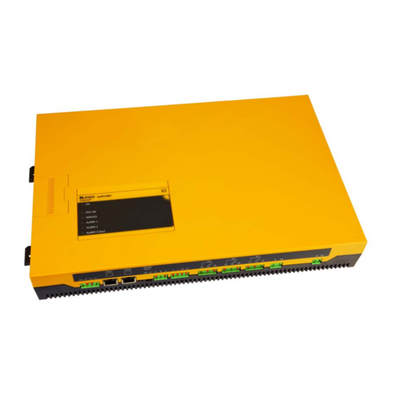
Insulation monitoring device
with residual current monitoring (isoPV1685PFR only)
for unearthed DC systems
for photovoltaic systems up to 1500 V
isoPV1685: software version D409 v2.0x
isoPV1685P : software version D525 v2.0x
isoPV1685PFR: software version D366 v1.0x
isoPV1685-1685PFR_D00007_02_M_XXEN/10.2016
Advertisement
Table of Contents

Related Manuals for Bender isoPV1685


Summary of Contents for Bender isoPV1685
- Page 1 Insulation monitoring device with residual current monitoring (isoPV1685PFR only) for unearthed DC systems for photovoltaic systems up to 1500 V isoPV1685: software version D409 v2.0x isoPV1685P : software version D525 v2.0x isoPV1685PFR: software version D366 v1.0x isoPV1685-1685PFR_D00007_02_M_XXEN/10.2016...
- Page 2 Bender GmbH & Co. KG © Bender GmbH & Co. KG All rights reserved. P.O.Box 1161 • 35301 Grünberg • Germany Londorfer Straße 65 • 35305 Grünberg • Germany Reprinting only with permission Tel.: +49 6401 807-0 • Fax: +49 6401 807-259 of the publisher.
-
Page 3: Table Of Contents
Device-specific safety instructions ................. 12 Address setting and termination ..................13 Intended use ........................... 13 3. Function ......................... 15 Device features isoPV1685, isoPV1685P and isoPV1685PFR ......... 15 Product description ......................15 Description of function ....................... 16 3.3.1 Insulation monitoring ......................17 3.3.2 Insulation fault location (isoPV1685P(FR)) .............. - Page 4 CAN bus ............................. 36 Error codes BMS and CAN bus ..................37 7. Settings ........................39 Setting the permissible system leakage capacitance or measurement speed . 39 Parameter setting with the tool iso1685-Set ............... 39 Factory settings ........................40 isoPV1685-1685PFR_D00007_02_M_XXEN/10.2016...
- Page 5 Table of Contents 8. Technical data ....................... 41 isoPV1685... data in tabular form ..................41 Standards, approvals and certifications ................ 44 Ordering data ......................... 44 Characteristic curves ......................45 8.4.1 The measurable leakage capacitance depends on the insulation resistance 45 8.4.2 Response time for insulation measurement ...............
-
Page 7: Important Information
This signal word indicates a low level risk that can result in minor or moderate injury or damage to property if not avoided. CAUTION This symbol denotes information intended to assist the user to make optimum use of the product. This operating manual describes the isoPV1685 series consisting of isoPV1685 and isoPV1685PFR. isoPV1685-1685PFR_D00007_02_M_XXEN/10.2016... -
Page 8: Technical Support
• Hardware and software update for Bender devices • Delivery of replacement devices in the event of faulty or incorrectly delivered Bender devices • Extended guarantee for Bender devices, which includes an in-house repair service or replace- ment devices at no extra cost... -
Page 9: Training Courses
Important information 1.2 Training courses Bender is happy to provide training regarding the use of test equipment. The dates of training courses and workshops can be found on the Internet at www.bender-de.com - > Know-how -> Seminars. 1.3 Delivery conditions Bender sale and delivery conditions apply. - Page 10 Important information isoPV1685-1685PFR_D00007_02_M_XXEN/10.2016...
-
Page 11: Safety Instructions
2.1 General safety instructions Part of the device documentation in addition to this manual is the enclosed "Safety instructions for Bender products". 2.2 Work activities on electrical installations Only qualified personnel are permitted to carry out the work necessary to install, commission and run a device or system. -
Page 12: Device-Specific Safety Instructions
When a monitored IT system contains galvanically coupled DC circuits, an insu- lation fault can only be detected correctly if the rectifier valves (e.g. rectifier di- ode, thyristors, IGBTs, frequency inverters, …) carry a minimum current of > 10 mA. isoPV1685-1685PFR_D00007_02_M_XXEN/10.2016... -
Page 13: Address Setting And Termination
(2…20 kHz). 2.4 Address setting and termination Correct address setting and termination of the isoPV1685... series insulation monitoring device is essential for correct functioning. Risk of bus errors! Double assignment of addresses on the respective BMS or CAN busses can cause serious malfunctions. - Page 14 Safety instructions isoPV1685-1685PFR_D00007_02_M_XXEN/10.2016...
-
Page 15: Function
3. Function 3.1 Device features isoPV1685, isoPV1685P and isoPV1685PFR Only device version isoPV1685PFR provides a locating current injector and residual current measure- ment! The device version isoPV1685PFR additionally ist able to perform a differential method. • Insulation monitoring of large-scale photovoltaic systems •... -
Page 16: Description Of Function
Insulation monitoring is carried out using an active measuring pulse which is superimposed onto the PV system to earth via the integrated coupling. isoPV1685: When the insulation resistance between the IT system and earth falls below the pre-set prewarning response value R , LED "Alarm 1"... -
Page 17: Insulation Monitoring
BMS master mode. For this purpose, the isoPV1685P(FR) has to communicate with the insulation fault locator via the BMS bus. During the insulation fault location process, the function of insulation resistance measurement is deactivated and the coupling is disconnected from the mains. isoPV1685-1685PFR_D00007_02_M_XXEN/10.2016... -
Page 18: Residual Current Monitoring (Isopv1685Pfr)
Automatic self test All supply voltages are continuously monitored. The following tests are continuously carried out in the background: - Connection E-KE - System polarity - Residual current transformer (connection, short-circuit, isoPV1685PFR only) - Temperature measurement - Pulse generator isoPV1685-1685PFR_D00007_02_M_XXEN/10.2016... -
Page 19: Manual Self Test
When the self test is started via the CAN bus, you can choose between an insulation fault measure- ment test or a residual current measurement test (isoPV1685PFR only). isoPV1685(P): During the insulation fault measurement test, the alarm relay K1 (11-12-14) and K2 (21-22-24)are switched over. K3 is not switched over. -
Page 20: Measured Value Transmission To The Control Inputs Of The Inverter
For the evaluation of the history memory, the Excel tool "iso1685 History.xlsx" can be made available. This tool allows csv.-file data to be processed and evaluated. By way of example, history memory en- tries are shown on page 48. The tool includes detailed information about the use. isoPV1685-1685PFR_D00007_02_M_XXEN/10.2016... -
Page 21: Device Overview
4. Device overview 4.1 Dimensions 5,2 mm isoPV1685 ® ISOMETER PGH ON SERVICE ALARM 1 ALARM 2 ALARM 3 (I ∆ 106 mm 39,8 mm 40,75 mm 55,7 mm 51 mm 368 mm 383 mm 401,5 mm isoPV1685-1685PFR_D00007_02_M_XXEN/10.2016... -
Page 22: Connection
- PGH ON: Insulation fault location (isoPV1685PFR) - SERVICE: Device error, Connection fault Memory Card (SDCard) - ALARM 1: Insulation fault - ALARM 2: Insulation fault iso1685FR isoPV1685 ® ® ISOMETER ISOMETER - ALARM 3: Residual current fault (isoPV1685PFR) PGH ON... -
Page 23: Display And Operating Controls
Change BMS address (SS8103) • Set maximum leakage capacitance (SS8103) • Change measurement speed (SS8103) • Reset Alarms (ST6101) Additionally, you can read out e.g. alarms from the μSD card. iso1685FR isoPV1685 ® ® ISOMETER ISOMETER PGH ON SERVICE SERVICE ALARM 1... -
Page 24: Alarm Leds On The Top Of The Enclosure
Device overview 4.3.3 Alarm LEDs on the top of the enclosure isoPV1685 ® ISOMETER PGH ON SERVICE ALARM 1 ALARM 2 ALARM 3 (I ∆ Beschreibung Power On indicator Flashes with a pulse duty factor of approx. 80 %. Device error: Lights continuously, when the device stops functioning (device stopped). -
Page 25: Installation, Connection And Commissioning Of The Device
If several devices are connected, the device does not function and does not signal insulation faults. Make sure CAUTION that only one insulation monitoring device is connected in each conductively connected system. isoPV1685-1685PFR_D00007_02_M_XXEN/10.2016... -
Page 26: Wiring Diagram
Perform a functional test using an earth fault via a suitable resistance. 5.2.2 Wiring diagram Connect the device with the help of the connection and terminal diagram. Use the adjacent legend. L1/+ L2/- isoPV1685 ® ISOMETER PGH ON SERVICE PGH ON ALARM 1... - Page 27 = measurement winding/kT, lT = test winding 31, 32, 34 Alarm relay K3 for internal device errors Description of relay assignment according to device type, see page 19; isoPV1685 only: 21, 22, 24 Alarm relay K2 for insulation faults isoPV1685PFR only:...
-
Page 28: Commissioning
Installation, connection and commissioning of the device 5.3 Commissioning 5.3.1 Commissioning flow chart insulation fault monitoring System = IT system ? isoPV1685 not suitable Un < DC1500 V ? isoPV1685 not suitable Deenergize the installation before connecting the device Device connection... -
Page 29: Commissioning Flow Chart Insulation Fault Location (Isopv1685P(Fr) Only)
CTs be tested? transformer Remove the resistor Alarm LEDs extinguished? Alarm relays switched? Delete alarm messages: Press reset button at the EDS... or call up the EDS reset in the EDS... menu The EDS... operates properly and is connected correctly isoPV1685-1685PFR_D00007_02_M_XXEN/10.2016... - Page 30 Installation, connection and commissioning of the device isoPV1685-1685PFR_D00007_02_M_XXEN/10.2016...
-
Page 31: Bms And Can Bus
The RS-485 interface, galvanically isolated from the device electronics, serves as a physical transmis- sion medium for the BMS protocol. When an isoPV1685…or other bus devices are interconnected via the BMS bus in a network, the BMS bus must be terminated at both ends with a 120 Ω resistor. -
Page 32: Topology Rs-485 Network
The number of bus nodes is restricted to 32 devices. When more devices are to be connected, Bender recommends to use a DI1 repeater. 6.1.3 BMS protocol This protocol is an essential part of the Bender measuring device interface (BMS bus protocol). Data transmission generally makes use of ASCII characters. Interface data are: •... -
Page 33: Commissioning Of An Rs-485 Network With Bms Protocol
BMS and CAN bus The isoPV1685… can only be operated as BMS-SLAVE! BMS master A master can query all measured values, alarm and operating messages from a slave. If bus address 1 is assigned to a device, this device automatically represents the master. That means that all addresses between 1 and 150 are cyclically scanned via the BMS bus for alarm and operating messages. -
Page 34: Setting The Bms Address
BMS- Adr. Switch position: Up = Off Down = On 6.1.6 Alarm and operating messages via the BMS bus Messages are transmitted to a maximum of 12 BMS channels. All alarm and operating messages which may occur are described below. isoPV1685-1685PFR_D00007_02_M_XXEN/10.2016... -
Page 35: Alarm Messages
Current locating current of the locating current injector PGH current (PGH); Channel occupied (isoPV1685P(FR) only) Temperature coupling Current temperature of the coupling L+ Temperature coupling Current temperature of the coupling L– Temperature PGH Current temperature of the locating current injector isoPV1685-1685PFR_D00007_02_M_XXEN/10.2016... -
Page 36: Resetting Error Messages
Starting the firmware update via the BMS bus The firmware can be updated via the BMS bus using the BMS Update Manager which can be obtained from Bender. 6.2 CAN bus Communication via the CAN interface is descriped in a separate document. The CAN bus can be ter- minated with a 120 Ω... -
Page 37: Error Codes Bms And Can Bus
9.75 0x80FF System Program sequence temperature measurement Re-start device 9.76 0x80FF System Program sequence history memory Re-start device 9.77 0x80FF System Program sequence console Re-start device 9.78 0x80FF System Program sequence self test Re-start device Stack error Re-start device isoPV1685-1685PFR_D00007_02_M_XXEN/10.2016... - Page 38 BMS and CAN bus isoPV1685-1685PFR_D00007_02_M_XXEN/10.2016...
-
Page 39: Settings
Bender provides this software free of charge and without warranty. By using the Software, you agree to use the software on your own risk. Bender is not responsi- ble for possible software errors or shortcomings and does not guarantee that the software is correctly and reliably. -
Page 40: Factory Settings
30 mA PGH current isoPV1685PFR only: Standby mode (disconnection from the mains) Reset to factory setting BMS address SS8103 BMS termination SS8100 CAN termination SS8102 Permissible system leakage capacitance ≤ 500 μF SS8103 Measurement speed Fast SS8103 isoPV1685-1685PFR_D00007_02_M_XXEN/10.2016... -
Page 41: Technical Data
8. Technical data 8.1 isoPV1685... data in tabular form ( )* = factory setting Insulation coordination acc. to IEC 60664-1 IEC 60664-3 Insulation coordination acc. to IEC 60664-1 Rated insulation voltage............................DC 1500 V Rated impulse voltage/pollution degree........................8 kV/2... - Page 42 Terminating resistor, can be connected (term. RS-485) ................120 Ω (0.5 W) Device address, BMS bus ..........................2…33 ( 2)* CAN: Protocol ......................... acc. to SMA/Bender specification V2.2 Frame format ..........................CAN 2.0A 11-bit identifier Baud rate ................................500 kbit/s Connection via 2 x RJ45 acc.
- Page 43 PCB fixation..........................lens head screw DIN7985TX Tightening torque..............................4.5 Nm Degreee of protection, internal components....................... IP30 Degree of protection, terminals ........................... IP30 Software version, isoPV1685 .......................... D409 V2.0x Software version, isoPV1685P ........................D525 V2.0x Software version, isoPV1685PFR ........................D366 V1.0x Weight .................................. ≤ 1300 g ( )* = factory setting isoPV1685-1685PFR_D00007_02_M_XXEN/10.2016...
-
Page 44: Standards, Approvals And Certifications
Technical data 8.2 Standards, approvals and certifications The isoPV1685 was designed according to the following standards: - DIN EN 61557-8 (VDE 0413-8) - IEC 61557-8 - IEC 61557-9 - IEC 61326-2-4 - IEC 60730-1 - DIN EN 60664-1 (VDE 0110-1) - UL1998 (Software) 8.3 Ordering data... -
Page 45: Characteristic Curves
Technical data 8.4 Characteristic curves 8.4.1 The measurable leakage capacitance depends on the insulation resistance 8.4.2 Response time for insulation measurement isoPV1685-1685PFR_D00007_02_M_XXEN/10.2016... - Page 46 Technical data isoPV1685-1685PFR_D00007_02_M_XXEN/10.2016...
-
Page 47: Response Time For Residual Current Measurement(Isopv1685Pfr Only)
Technical data 8.4.3 Response time for residual current measurement(isoPV1685PFR only) isoPV1685-1685PFR_D00007_02_M_XXEN/10.2016... -
Page 48: Example Of Alarms Stored In The History Memory
Technical data 8.4.4 Example of alarms stored in the history memory isoPV1685-1685PFR_D00007_02_M_XXEN/10.2016... -
Page 49: Index
RS-485 interface 31 Error codes 37 RS-485 network - Correct arrangement 32 - Wrong arrangement 32 Factory settings 28 Safety instructions 7 History memory 36 SD card 23 Self test - after connection to the supply volt- age 18 isoPV1685-1685PFR_D00007_02_M_XXEN/10.2016... - Page 52 Bender GmbH & Co. KG P.O.Box 1161 • 35301 Grünberg • Germany Londorfer Straße 65 • 35305 Grünberg • Germany Tel.: +49 6401 807-0 • Fax: +49 6401 807-259 E-mail: info@bender.de • www.bender.de Fotos: Bender Archiv und bendersystembau Archiv.
Need help?
Do you have a question about the isoPV1685 and is the answer not in the manual?
Questions and answers