
Related Manuals for KODU UA1407


Summary of Contents for KODU UA1407
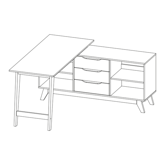
- Page 1 DESK 4 SHELF 3 DRAWERS ASSEMBLY INSTRUCTIONS AFTER SALES SUPPORT ASSEMBLY INSTRUCTIONS 1300 777 137 UA1407 UA1457...
- Page 2 Please do not drag and pull your furniture. ASSEMBLY REQUIREMENTS Equipment: phillips head screwdriver, flat head screwdriver and hammer 2 x adults required 2m x 2m assembly space required 2 hour assembly time approx. 2 of 31 AFTER SALES SUPPORT ASSEMBLY INSTRUCTIONS 1300 777 137 UA1407 UA1457...
- Page 3 Quickfit head should be in the centre of the cam lock when the two panels are joined. Turn cam lock clockwise to tighten. Cam lock should be inserted before quickfit. 3 of 31 AFTER SALES SUPPORT ASSEMBLY INSTRUCTIONS 1300 777 137 UA1407 UA1457...
- Page 4 8 x N 24 x O Screw Bolt Shelf Support Nail 7 x P 6 x Q 6 x R Nail Leg Outer Drawer Runner Inner Drawer Runner 4 of 31 AFTER SALES SUPPORT ASSEMBLY INSTRUCTIONS 1300 777 137 UA1407 UA1457...
- Page 5 1 PC 1 PC 1 PC 1 PC 3 PCS 2 PCS 1 PC 2 PCS 3 PCS 3 PCS 6 PCS 3 PCS 2 PCS 1 PC 5 of 31 AFTER SALES SUPPORT ASSEMBLY INSTRUCTIONS 1300 777 137 UA1407 UA1457...
- Page 6 PARTS LIST (CONT.) 1 PC 1 PC 1 PC 1 PC 1 PC 3 PCS 1 PC 2 PCS 1 PC 1 PC 6 of 31 AFTER SALES SUPPORT ASSEMBLY INSTRUCTIONS 1300 777 137 UA1407 UA1457...
- Page 7 Insert cam locks (A) and wooden dowels (D) to parts 3, 4, 5 and 6. A x 8 Insert quickfit screws (B) to parts 1, 3, 4, 5 and 6, as shown. B x 20 D x 16 7 of 31 AFTER SALES SUPPORT ASSEMBLY INSTRUCTIONS 1300 777 137 UA1407 UA1457...
- Page 8 Insert cam locks (A) to parts 8, 9 and 15. A x 16 Insert wooden dowels (D) to parts 7 and 9, as shown. D x 16 8 of 31 AFTER SALES SUPPORT ASSEMBLY INSTRUCTIONS 1300 777 137 UA1407 UA1457...
- Page 9 Insert wooden dowels (D) to parts 16, 17, 20, 21 and 23. Insert wooden dowerls (E) to parts 25 and 26, as shown. D x 14 E x 4 9 of 31 AFTER SALES SUPPORT ASSEMBLY INSTRUCTIONS 1300 777 137 UA1407 UA1457...
- Page 10 ASSEMBLY INSTRUCTIONS STEP 4 Fix outer drawer runners (Q) to parts 5 and 6 using screws (I), as shown. I x 18 Q x 6 10 of 31 AFTER SALES SUPPORT ASSEMBLY INSTRUCTIONS 1300 777 137 UA1407 UA1457...
- Page 11 Attach parts 5 and 6 to parts 7 and 9, as shown. C x 4 Turn cam locks clockwise to tighten. Attach covers (C) to cam locks, as shown. 11 of 31 AFTER SALES SUPPORT ASSEMBLY INSTRUCTIONS 1300 777 137 UA1407 UA1457...
- Page 12 Attach parts 3 and 5 to part 8. C x 8 Attach parts 4 and 6 to part 8. Turn cam locks clockwise to tighten. Attach covers (C) to cam locks, as shown. 12 of 31 AFTER SALES SUPPORT ASSEMBLY INSTRUCTIONS 1300 777 137 UA1407 UA1457...
- Page 13 STEP 7 Fix part 2 to parts 3, 4, 5, 6 and 9 using screws (F) and allen key (H), as shown. F x 9 H x 1 13 of 31 AFTER SALES SUPPORT ASSEMBLY INSTRUCTIONS 1300 777 137 UA1407 UA1457...
- Page 14 Attach parts 16 and 17 to parts 15, as shown. Turn cam locks clockwise to tighten. J x 2 Attach covers (C) to cam locks, as shown. 14 of 31 AFTER SALES SUPPORT ASSEMBLY INSTRUCTIONS 1300 777 137 UA1407 UA1457...
- Page 15 STEP 9 Fix parts 15, 16 and 17 to part 2 using screw (K). K x 14 Fix legs (P) to parts 16, as shown. P x 5 15 of 31 AFTER SALES SUPPORT ASSEMBLY INSTRUCTIONS 1300 777 137 UA1407 UA1457...
- Page 16 ASSEMBLY INSTRUCTIONS STEP 10 Insert shelf pins (N) to parts 3, 4, 5 and 6, as shown. N x 8 16 of 31 AFTER SALES SUPPORT ASSEMBLY INSTRUCTIONS 1300 777 137 UA1407 UA1457...
- Page 17 ASSEMBLY INSTRUCTIONS STEP 11 Insert shelves 10 to assembled unit, as shown. 17 of 31 AFTER SALES SUPPORT ASSEMBLY INSTRUCTIONS 1300 777 137 UA1407 UA1457...
- Page 18 ASSEMBLY INSTRUCTIONS STEP 12 Fix parts 20 and 21 to parts 22 using screws (F) and allen key (H), as shown. F x 8 H x 1 18 of 31 AFTER SALES SUPPORT ASSEMBLY INSTRUCTIONS 1300 777 137 UA1407 UA1457...
- Page 19 ASSEMBLY INSTRUCTIONS STEP 13 Fix parts 24 to parts 20 and 21 using screws (J), as shown. J x 4 19 of 31 AFTER SALES SUPPORT ASSEMBLY INSTRUCTIONS 1300 777 137 UA1407 UA1457...
- Page 20 Fix part 23 to parts 25 and 26 using allen key (H), bolt (L) and nut (M), as shown. H x 1 L x 2 M x 2 20 of 31 AFTER SALES SUPPORT ASSEMBLY INSTRUCTIONS 1300 777 137 UA1407 UA1457...
- Page 21 ASSEMBLY INSTRUCTIONS STEP 15 Attach parts 25 and 26 to parts 24 using screws (J), a shown. J x 12 21 of 31 AFTER SALES SUPPORT ASSEMBLY INSTRUCTIONS 1300 777 137 UA1407 UA1457...
- Page 22 Fix parts 25 and 26 to part 22 using screws (G) and allen key (H), as shown. G x 4 H x 1 G G G G G G G G G G G G 22 of 31 AFTER SALES SUPPORT ASSEMBLY INSTRUCTIONS 1300 777 137 UA1407 UA1457...
- Page 23 STEP 17 Fix parts 20, 21 and 22 to part 19 using scerws (K), as shown. K x 17 K K K K K K K K K 23 of 31 AFTER SALES SUPPORT ASSEMBLY INSTRUCTIONS 1300 777 137 UA1407 UA1457...
- Page 24 ASSEMBLY INSTRUCTIONS STEP 18 Fix legs (P) to parts 25 and 26, as shown. P x 2 24 of 31 AFTER SALES SUPPORT ASSEMBLY INSTRUCTIONS 1300 777 137 UA1407 UA1457...
- Page 25 Fix parts 1 to parts 20 and 21 using screws (F) and allen key (H), a shown. F x 4 H x 1 OPTION 1 F F F F F F F F F F F F OPTION 2 F F F 25 of 31 AFTER SALES SUPPORT ASSEMBLY INSTRUCTIONS 1300 777 137 UA1407 UA1457...
- Page 26 C x 8 Turn cam locks clockwise to tighten. Attach cam lock covers (C) to parts 3, 4, 5 and 6, as shown. OPTION 1 OPTION 2 26 of 31 AFTER SALES SUPPORT ASSEMBLY INSTRUCTIONS 1300 777 137 UA1407 UA1457...
- Page 27 ASSEMBLY INSTRUCTIONS STEP 21 Fix parts 11 and 12 to parts 13 using screws (K), as shown. K x 24 27 of 31 AFTER SALES SUPPORT ASSEMBLY INSTRUCTIONS 1300 777 137 UA1407 UA1457...
- Page 28 ASSEMBLY INSTRUCTIONS STEP 22 Fix part 14 to assembled drawers using nails (O), as shown. O x 24 28 of 31 AFTER SALES SUPPORT ASSEMBLY INSTRUCTIONS 1300 777 137 UA1407 UA1457...
- Page 29 ASSEMBLY INSTRUCTIONS STEP 23 Fix inner drawer runners (R) to parts 14 using screws (I), as shown. I x 18 R x 6 29 of 31 AFTER SALES SUPPORT ASSEMBLY INSTRUCTIONS 1300 777 137 UA1407 UA1457...
- Page 30 ASSEMBLY INSTRUCTIONS STEP 24 Insert drawers into assembled unit, as shown. 30 of 31 AFTER SALES SUPPORT ASSEMBL Y INSTRUCTIONS 1300 777 137 UA1407 UA1457...
- Page 31 Please note: the maximum recommended weight for this desk is : • Each Top: 15KG • Each Drawer: 10KG • Each Shelf: 10KG Your desk is ready for use. 31 of 31 AFTER SALES SUPPORT ASSEMBLY INSTRUCTIONS 1300 777 137 UA1407 UA1457...
Need help?
Do you have a question about the UA1407 and is the answer not in the manual?
Questions and answers