
Related Manuals for KODU UH10877


Summary of Contents for KODU UH10877
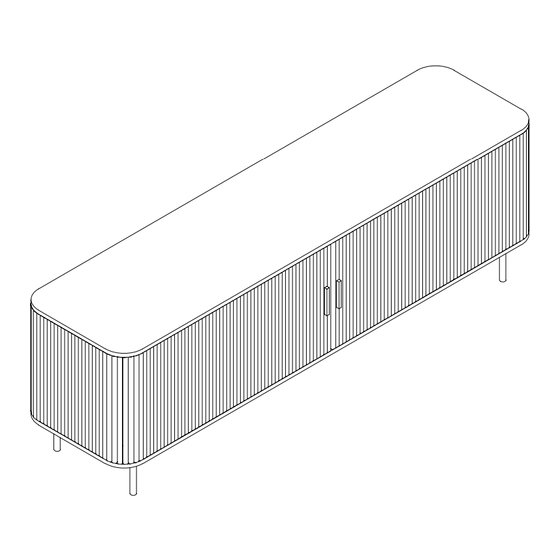
- Page 1 TV UNIT 2 DOORS ASSEMBLY INSTRUCTIONS AFTER SALES SUPPORT ASSEMBLY INSTRUCTIONS 1300 777 137 UH10877...
- Page 2 Please do not drag and pull your furniture. ASSEMBLY REQUIREMENTS Equipment: phillips head screwdriver, flat head screwdriver and hammer 1 x adults required 1m x 1m assembly space required 1 hour assembly time approx. 2 of 23 AFTER SALES SUPPORT ASSEMBLY INSTRUCTIONS 1300 777 137 UH10877...
- Page 3 Quickfit head should be in the centre of the cam lock when the two panels are joined. Turn cam lock clockwise to tighten. Cam lock should be inserted before quickfit. 3 of 23 AFTER SALES SUPPORT ASSEMBLY INSTRUCTIONS 1300 777 137 UH10877...
-
Page 4: Hardware List
4 x F Wooden Dowel Handle Screw 1 x G 25 x H 16 x I Wall Bracket Screw Screw 16 x J 1 x K Wedge Wall Plug 4 of 23 AFTER SALES SUPPORT ASSEMBLY INSTRUCTIONS 1300 777 137 UH10877... -
Page 5: Parts List
1 PC 1 PC 1 PC 1 PC 1 PC 2 PCS 4 PCS 1 PC 1 PC 2 PCS 4 PCS 2 PCS 1 PC 1 PC 5 of 23 AFTER SALES SUPPORT ASSEMBLY INSTRUCTIONS 1300 777 137 UH10877... - Page 6 ASSEMBLY INSTRUCTIONS STEP 1 Insert quickfit screws (B) to parts 3 and 4, as shown. B x 4 6 of 23 AFTER SALES SUPPORT ASSEMBLY INSTRUCTIONS 1300 777 137 UH10877...
- Page 7 ASSEMBLY INSTRUCTIONS STEP 2 Insert quickfit screws (B) to part 5, as shown. B x 4 7 of 23 AFTER SALES SUPPORT ASSEMBLY INSTRUCTIONS 1300 777 137 UH10877...
- Page 8 ASSEMBLY INSTRUCTIONS STEP 3 Insert quickfit screws (B) to part 6, as shown. B x 4 8 of 23 AFTER SALES SUPPORT ASSEMBLY INSTRUCTIONS 1300 777 137 UH10877...
- Page 9 Insert cam locks (C) and wooden dowel (D) to part 8. C x 4 Attach parts 3 and 5 to part 8, as shown. Turn cam locks clockwise to tighten. D x 6 9 of 23 AFTER SALES SUPPORT ASSEMBLY INSTRUCTIONS 1300 777 137 UH10877...
- Page 10 Insert cam locks (C) and wooden dowel (D) to part 8.. C x 4 Attach parts 4 and 6 to part 8, as shown. Turn cam locks clockwise to tighten. D x 6 10 of 23 AFTER SALES SUPPORT ASSEMBLY INSTRUCTIONS 1300 777 137 UH10877...
- Page 11 Insert wooden dowels (D) and cam lock (C) to part 7. C x 2 Attach part 7 to part 5, as shown. Turn cam locks clockwise to tighten. D x 2 11 of 23 AFTER SALES SUPPORT ASSEMBLY INSTRUCTIONS 1300 777 137 UH10877...
- Page 12 Insert wooden dowels (D) and cam lock (C) to part 7. C x 2 Attach part 6 to part 7, as shown. Turn cam locks clockwise to tighten. D x 2 12 of 23 AFTER SALES SUPPORT ASSEMBLY INSTRUCTIONS 1300 777 137 UH10877...
- Page 13 Slide part 9 between grooves of parts 4, 6 and 8. Slide part 9 between grooves of parts 3, 5 and 8. Slide part 11 between grooves of parts 5, 6 and 7, as shown. 13 of 23 AFTER SALES SUPPORT ASSEMBLY INSTRUCTIONS 1300 777 137 UH10877...
- Page 14 Insert quickfit screws (B) to part 1. B x 10 Fix wall bracket (G) to part 1 using screw (H), as shown. G x 1 H x 1 14 of 23 AFTER SALES SUPPORT ASSEMBLY INSTRUCTIONS 1300 777 137 UH10877...
- Page 15 Insert cam locks (C) to parts 3, 4, 5, 6 and 15, 16. Fix part 1 to parts 3, 4, 5, 6 and 15, 16, as shown. D x 8 Turn cam locks clockwise to tighten. D D D 15 of 23 AFTER SALES SUPPORT ASSEMBLY INSTRUCTIONS 1300 777 137 UH10877...
- Page 16 Slide part 9 between grooves of parts 4, 6 and 8. Slide part 9 between grooves of parts 3, 5 and 8. Slide part 10 between grooves of parts 5, 6 and 7, as shown. 16 of 23 AFTER SALES SUPPORT ASSEMBLY INSTRUCTIONS 1300 777 137 UH10877...
- Page 17 ASSEMBLY INSTRUCTIONS STEP 12 Fix handle (E) to parts 12 using screws (F), as shown. E x 2 Repeat step twice. F x 4 17 of 23 AFTER SALES SUPPORT ASSEMBLY INSTRUCTIONS 1300 777 137 UH10877...
- Page 18 ASSEMBLY INSTRUCTIONS STEP 13 Slide parts 12 into grooves of part 1. 18 of 23 AFTER SALES SUPPORT ASSEMBLY INSTRUCTIONS 1300 777 137 UH10877...
- Page 19 Insert wooden dowels (D) to parts 3, 4, 5 and 6. A x 10 Fix part 2 to parts 3, 4, 5, 6 and 12, 15, 16 using screws (A), as shown. D x 8 19 of 23 AFTER SALES SUPPORT ASSEMBLY INSTRUCTIONS 1300 777 137 UH10877...
- Page 20 Fix part 13 and 14 to part 2 using screws (H), as shown. H x 24 H H H H H H H H H H H H H H H H H H 20 of 23 AFTER SALES SUPPORT ASSEMBLY INSTRUCTIONS 1300 777 137 UH10877...
- Page 21 ASSEMBLY INSTRUCTIONS STEP 16 Secure parts 9, 10 and 11 by fixing wedges (J) with screws (I), as shown. I x 16 J x 16 21 of 23 AFTER SALES SUPPORT ASSEMBLY INSTRUCTIONS 1300 777 137 UH10877...
- Page 22 Should you choose not to affix the product to the wall, serious injury may be caused if the product tips over. Please consider the wall mounting & fixing guide when securing your TV unit. K x 1 WALL 22 of 23 AFTER SALES SUPPORT ASSEMBLY INSTRUCTIONS 1300 777 137 UH10877...
- Page 23 ASSEMBLY INSTRUCTIONS STEP 18 Maximum recommended weight is 15 kg on top, 5 kg inside each shelf. Your TV unit 2 doors is ready for use. 23 of 23 AFTER SALES SUPPORT ASSEMBLY INSTRUCTIONS 1300 777 137 UH10877...
Need help?
Do you have a question about the UH10877 and is the answer not in the manual?
Questions and answers