
Related Manuals for KODU UH11049


Summary of Contents for KODU UH11049
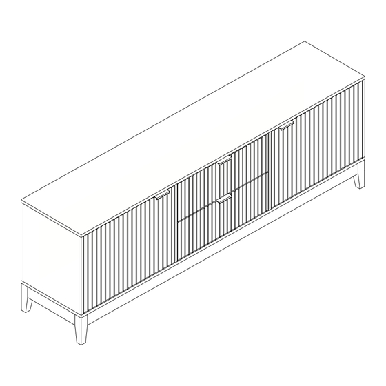
- Page 1 TV UNIT 2 DOORS 2 DRAWERS ASSEMBLY INSTRUCTIONS AFTER SALES SUPPORT ASSEMBLY INSTRUCTIONS 1300 777 137 UH11049 UH11050...
- Page 2 Please do not drag and pull your furniture. ASSEMBLY REQUIREMENTS Equipment: phillips head screwdriver, flat head screwdriver 2 x adults required 2m x 2m assembly space required 1.5 hour assembly time approx. 2 of 36 AFTER SALES SUPPORT ASSEMBLY INSTRUCTIONS 1300 777 137 UH11049 UH11050...
- Page 3 Quickfit head should be in the centre of the cam lock when the two panels are joined. Turn cam lock clockwise to tighten. Cam lock should be inserted before quickfit. 3 of 36 AFTER SALES SUPPORT ASSEMBLY INSTRUCTIONS 1300 777 137 UH11049 UH11050...
- Page 4 Screw Screw Screw 24 x G 12 x H 4 x I Screw Wedge Handle 8 x J 8 x K 8 x L Washer Bolts Washer 4 of 36 AFTER SALES SUPPORT ASSEMBLY INSTRUCTIONS 1300 777 137 UH11049 UH11050...
- Page 5 Outer Drawer Runner Outer Drawer Runner Inner Drawer Runner 2 x V 2 x W 2 x X 4 x Y Inner Drawer Runner Wall Bracket Wall Plug Screw 5 of 36 AFTER SALES SUPPORT ASSEMBLY INSTRUCTIONS 1300 777 137 UH11049 UH11050...
- Page 6 PARTS LIST 1 PC 1 PC 1 PC 1 PC 1 PC 1 PC 2 PCS 4 PCS 1 PC 1 PC 2 PCS 2 PCS 6 of 36 AFTER SALES SUPPORT ASSEMBLY INSTRUCTIONS 1300 777 137 UH11049 UH11050...
- Page 7 PARTS LIST 4 PCS 2 PCS 4 PCS 2 PCS 2 PCS 2 PCS 2 PCS 2 PCS 2 PCS 1 PC 3 PCS 2 PCS 7 of 36 AFTER SALES SUPPORT ASSEMBLY INSTRUCTIONS 1300 777 137 UH11049 UH11050...
- Page 8 Fix door stoppers (O) to part 1 using screws (E). Fix wall brackets (W) to part 1 using screws (Y), as shown. E x 4 O x 2 W x 2 Y x 2 8 of 36 AFTER SALES SUPPORT ASSEMBLY INSTRUCTIONS 1300 777 137 UH11049 UH11050...
- Page 9 ASSEMBLY INSTRUCTIONS STEP 2 Insert quickfit screw (A) to part 2, as shown. A x 14 9 of 36 AFTER SALES SUPPORT ASSEMBLY INSTRUCTIONS 1300 777 137 UH11049 UH11050...
- Page 10 ASSEMBLY INSTRUCTIONS STEP 3 Insert quickfit screw (A) to part 4 and 5, as shown. A x 4 10 of 36 AFTER SALES SUPPORT ASSEMBLY INSTRUCTIONS 1300 777 137 UH11049 UH11050...
- Page 11 ASSEMBLY INSTRUCTIONS STEP 4 Fix outer drawer runners (T) to part 4 using screws (D), as shown. D x 6 T x 2 11 of 36 AFTER SALES SUPPORT ASSEMBLY INSTRUCTIONS 1300 777 137 UH11049 UH11050...
- Page 12 ASSEMBLY INSTRUCTIONS STEP 5 Fix outer drawer runners (T) to part 5 using screws (D), as shown. D x 6 S x 2 12 of 36 AFTER SALES SUPPORT ASSEMBLY INSTRUCTIONS 1300 777 137 UH11049 UH11050...
- Page 13 STEP 6 Insert cam locks (B) to part 22. B x 4 Attached part 22 to parts 4 and 5, as shown. Turn cam locks clockwise to tighten. 13 of 36 AFTER SALES SUPPORT ASSEMBLY INSTRUCTIONS 1300 777 137 UH11049 UH11050...
- Page 14 Insert wooden dowel (C) to parts 3, 4, 5 and 6. B x 8 Attach part 1 to parts 3, 4, 5 and 6, as shown. Turn cam locks clockwise to tighten. C x 8 14 of 36 AFTER SALES SUPPORT ASSEMBLY INSTRUCTIONS 1300 777 137 UH11049 UH11050...
- Page 15 ASSEMBLY INSTRUCTIONS STEP 8 Insert parts 8, 23 and 24 into the grooves of parts 1, 3, 4 5 and 6, as shown. 15 of 36 AFTER SALES SUPPORT ASSEMBLY INSTRUCTIONS 1300 777 137 UH11049 UH11050...
- Page 16 ASSEMBLY INSTRUCTIONS STEP 9 Screw adjustable feet (Q) to part 14, as shown. Q x 2 16 of 36 AFTER SALES SUPPORT ASSEMBLY INSTRUCTIONS 1300 777 137 UH11049 UH11050...
- Page 17 ASSEMBLY INSTRUCTIONS STEP 10 Fix parts 14 to part 2 using screws (G), as shown. G x 4 17 of 36 AFTER SALES SUPPORT ASSEMBLY INSTRUCTIONS 1300 777 137 UH11049 UH11050...
- Page 18 Insert wooden dowel (C) to parts 3, 4, 5 and 6. Fix part 2 to parts 3, 4, 5 and 6 using screws (G), as shown. G x 8 18 of 36 AFTER SALES SUPPORT ASSEMBLY INSTRUCTIONS 1300 777 137 UH11049 UH11050...
- Page 19 ASSEMBLY INSTRUCTIONS STEP 12 Fix parts 15 to parts 11 and 12 using screws (F), as shown. F x 16 19 of 36 AFTER SALES SUPPORT ASSEMBLY INSTRUCTIONS 1300 777 137 UH11049 UH11050...
- Page 20 ASSEMBLY INSTRUCTIONS STEP 13 Insert wooden dowels (C) to part 2, as shown. C x 8 20 of 36 AFTER SALES SUPPORT ASSEMBLY INSTRUCTIONS 1300 777 137 UH11049 UH11050...
- Page 21 Insert cam locks (B) to parts 11 and 12. B x 14 Attach the assembled unit to part 2, as shown. Turn cam locks clockwise to tighten. 21 of 36 AFTER SALES SUPPORT ASSEMBLY INSTRUCTIONS 1300 777 137 UH11049 UH11050...
- Page 22 Fix parts 13 to parts 15 using washers (L), washers (K) and botls (J), as shown. K x 8 L x 8 R x 4 L L L L L L L L L L L K 22 of 36 AFTER SALES SUPPORT ASSEMBLY INSTRUCTIONS 1300 777 137 UH11049 UH11050...
- Page 23 Fix handle (I) to part 9 and 10 using screws (D). D x 12 Fix hinges (P) to parts 9 and 10 using screws (D), as shown. I x 2 P x 4 23 of 36 AFTER SALES SUPPORT ASSEMBLY INSTRUCTIONS 1300 777 137 UH11049 UH11050...
- Page 24 ASSEMBLY INSTRUCTIONS STEP 17 Insert shelf support (N) to parts 3, 4, 5 and 6. N x 8 Put parts 7 on shelf support (N), as shown. 24 of 36 AFTER SALES SUPPORT ASSEMBLY INSTRUCTIONS 1300 777 137 UH11049 UH11050...
- Page 25 To adjust the gap from the door to the main frame turn the screw clockwise or anti-clockwise as needed. 25 of 36 AFTER SALES SUPPORT ASSEMBLY INSTRUCTIONS 1300 777 137 UH11049 UH11050...
- Page 26 To adjust the gap from the door to the main frame turn the screw clockwise or anti-clockwise as needed. 26 of 36 AFTER SALES SUPPORT ASSEMBLY INSTRUCTIONS 1300 777 137 UH11049 UH11050...
- Page 27 STEP 20 Fix inner drawer runners (U and V) to parts 17 and 18 using screws (D), as shown. D x 8 U x 2 V x 2 27 of 36 AFTER SALES SUPPORT ASSEMBLY INSTRUCTIONS 1300 777 137 UH11049 UH11050...
- Page 28 IInsert quickfit screws (A) to part 16. A x 10 Fix the handle (I) to part 16 using screws (D), as shown. D x 4 I x 2 28 of 36 AFTER SALES SUPPORT ASSEMBLY INSTRUCTIONS 1300 777 137 UH11049 UH11050...
- Page 29 ASSEMBLY INSTRUCTIONS STEP 22 Fix part 19 to parts 17, 18 and 21 using screws (G), as shown. G x 10 29 of 36 AFTER SALES SUPPORT ASSEMBLY INSTRUCTIONS 1300 777 137 UH11049 UH11050...
- Page 30 ASSEMBLY INSTRUCTIONS STEP 23 Insert part 20 into grooves between parts 17, 18 and 19, as shown. 30 of 36 AFTER SALES SUPPORT ASSEMBLY INSTRUCTIONS 1300 777 137 UH11049 UH11050...
- Page 31 Insert cam locks (B) to parts 17, 18 and 21. B x 10 Fix part 16 to parts 17, 18 and 21, as shown. Turn cam locks clockwise to tighten. 31 of 36 AFTER SALES SUPPORT ASSEMBLY INSTRUCTIONS 1300 777 137 UH11049 UH11050...
- Page 32 ASSEMBLY INSTRUCTIONS STEP 25 Insert drawers into assembled unit, as shown. 32 of 36 AFTER SALES SUPPORT ASSEMBLY INSTRUCTIONS 1300 777 137 UH11049 UH11050...
- Page 33 ASSEMBLY INSTRUCTIONS STEP 26 To secure part 8 and 24, fix wedges (H) using screws (E), as shown. E x 12 H x 12 33 of 36 AFTER SALES SUPPORT ASSEMBLY INSTRUCTIONS 1300 777 137 UH11049 UH11050...
- Page 34 Should you choose not to affix the product to the wall, serious injury may be caused if the product tips over. Please consider the wall mounting & fixing guide when securing your TV unit. WALL WALL WALL G G G 34 of 36 AFTER SALES SUPPORT ASSEMBLY INSTRUCTIONS 1300 777 137 UH11049 UH11050...
- Page 35 Maximum recommended weight is 5kg for each drawer, 5kg for shelves and 20 kg for top. Your TV unit 2 doors 2 drawers is ready for use. 35 of 36 AFTER SALES SUPPORT ASSEMBLY INSTRUCTIONS 1300 777 137 UH11049 UH11050...
- Page 36 TV & HiFi than the plasterboard. Always check the speakers and satellite dishes, etc. fixing is secure to the retaining wall. 36 of 36 AFTER SALES SUPPORT ASSEMBLY INSTRUCTIONS 1300 777 137 UH11049 UH11050...
Need help?
Do you have a question about the UH11049 and is the answer not in the manual?
Questions and answers