
Related Manuals for KODU UH0000058


Summary of Contents for KODU UH0000058
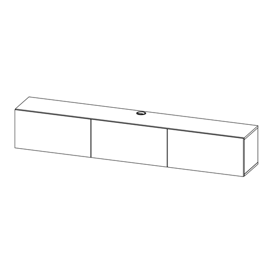
- Page 1 FLOATING TV UNIT 3 DOORS ASSEMBLY INSTRUCTIONS AFTER SALES SUPPORT ASSEMBLY INSTRUCTIONS 1300 777 137 UH0000058 UH0000254 UH0000255 UH0000256 UH0000257...
-
Page 2: Assembly Requirements
Please do not drag and pull your furniture. ASSEMBLY REQUIREMENTS 2 x adults required 2m x 2m assembly space required 1 hour assembly time approx. of 22 AFTER SALES SUPPORT ASSEMBLY INSTRUCTIONS 1300 777 137 UH0000058 UH0000254 UH0000255 UH0000256 UH0000257... - Page 3 ANTI-TOPPLING WARNING CHILDREN HAVE DIED FORM FURNITURE TIPOVER. of 22 AFTER SALES SUPPORT ASSEMBLY INSTRUCTIONS 1300 777 137 UH0000058 UH0000254 UH0000255 UH0000256 UH0000257 UH0000058 UH0000254 UH0000255 UH0000256 UH0000257...
- Page 4 WRONG Quickfit head should be in the centre of the cam lock when the two panels are joined. Cam lock should be inserted before quickfit. of 22 AFTER SALES SUPPORT ASSEMBLY INSTRUCTIONS 1300 777 137 UH0000058 UH0000254 UH0000255 UH0000256 UH0000257...
-
Page 5: Hardware List
1 x J Allen Key Hinge Screw L Bracket Wire 3 x K 5 x L 5 x M Chrome Stay 8" Wall Plug Screw of 22 AFTER SALES SUPPORT ASSEMBLY INSTRUCTIONS 1300 777 137 UH0000058 UH0000254 UH0000255 UH0000256 UH0000257... -
Page 6: Parts List
PARTS LIST 1 PC 1 PC 1 PC 1 PC 2 PCS 1 PC 3 PCS of 22 AFTER SALES SUPPORT ASSEMBLY INSTRUCTIONS 1300 777 137 UH0000058 UH0000254 UH0000255 UH0000256 UH0000257... - Page 7 Insert cam locks (A) and wooden dowels (D) to parts 3, 4, 5 and 6. A x 16 Insert quickfit screws (B) to parts 1, 3 and 4, as shown. B x 16 D x 22 of 22 AFTER SALES SUPPORT ASSEMBLY INSTRUCTIONS 1300 777 137 UH0000058 UH0000254 UH0000255 UH0000256 UH0000257...
- Page 8 ASSEMBLY INSTRUCTIONS STEP 2 Fix L brackets (H) to parts 1, 3 and 4 using screws (G), as shown. G x 4 H x 4 of 22 AFTER SALES SUPPORT ASSEMBLY INSTRUCTIONS 1300 777 137 UH0000058 UH0000254 UH0000255 UH0000256 UH0000257...
- Page 9 STEP 3 Attach part 6 to parts 3 and 4. C x 4 Turn cam locks clockwise to tighten. Attach cam lock covers (C), as shown. of 22 AFTER SALES SUPPORT ASSEMBLY INSTRUCTIONS 1300 777 137 UH0000058 UH0000254 UH0000255 UH0000256 UH0000257...
- Page 10 Attach part 1 to parts 3, 4 and 6. C x 8 Turn cam locks clockwise to tighten. Attach cam lock covers (C), as shown. of 22 AFTER SALES SUPPORT ASSEMBLY INSTRUCTIONS 1300 777 137 UH0000058 UH0000254 UH0000255 UH0000256 UH0000257...
- Page 11 ASSEMBLY INSTRUCTIONS STEP 5 Attach part 1 to parts 5. C x 4 Turn cam locks clockwise to tighten. Attach cam lock covers (C), as shown. of 22 AFTER SALES SUPPORT ASSEMBLY INSTRUCTIONS 1300 777 137 UH0000058 UH0000254 UH0000255 UH0000256 UH0000257...
- Page 12 ASSEMBLY INSTRUCTIONS STEP 6 Fix part 6 to parts 5 using screws (E) and allen key (F), as shown. E x 2 F x 1 of 22 AFTER SALES SUPPORT ASSEMBLY INSTRUCTIONS 1300 777 137 UH0000058 UH0000254 UH0000255 UH0000256 UH0000257...
- Page 13 ASSEMBLY INSTRUCTIONS STEP 7 Fix L brackets (H) to part 6 using screws (G), as shown. G x 4 of 22 AFTER SALES SUPPORT ASSEMBLY INSTRUCTIONS 1300 777 137 UH0000058 UH0000254 UH0000255 UH0000256 UH0000257...
- Page 14 Fix part 2 to parts 3, 4, 5 and 6 using screws (E) and allen key (F), as shown. E x 12 F x 1 of 22 AFTER SALES SUPPORT ASSEMBLY INSTRUCTIONS 1300 777 137 UH0000058 UH0000254 UH0000255 UH0000256 UH0000257...
- Page 15 ASSEMBLY INSTRUCTIONS STEP 9 Fix hinges (I) to parts 7 using screw (G), as shown. G x 12 I x 6 of 22 AFTER SALES SUPPORT ASSEMBLY INSTRUCTIONS 1300 777 137 UH0000058 UH0000254 UH0000255 UH0000256 UH0000257...
- Page 16 To adjust the door laterally adjust the screw as shown by turning clockwise or anti-clockwise. To adjust the door vertically loosen the screw as shown and move up and down as needed. anti-clockwise as needed. of 22 AFTER SALES SUPPORT ASSEMBLY INSTRUCTIONS 1300 777 137 UH0000058 UH0000254 UH0000255 UH0000256 UH0000257...
- Page 17 STEP 11 Fix chrome stay 8" (K) to parts 3, 4, 5 and 7 using screws (G), as shown. G x 15 K x 3 of 22 AFTER SALES SUPPORT ASSEMBLY INSTRUCTIONS 1300 777 137 UH0000058 UH0000254 UH0000255 UH0000256 UH0000257...
- Page 18 Mark the holes on the wall by using the pencil (not supplied) . Use the power drill to drill the marking point on the wall, as shown. STEP 1 STEP 2 WALL of 22 AFTER SALES SUPPORT ASSEMBLY INSTRUCTIONS 1300 777 137 UH0000058 UH0000254 UH0000255 UH0000256 UH0000257...
- Page 19 Fix wall plug (M) into the wall. L x 5 Assemble part 6 to the wall by using screws (L) , as shown. M x 5 WALL WALL of 22 AFTER SALES SUPPORT ASSEMBLY INSTRUCTIONS 1300 777 137 UH0000058 UH0000254 UH0000255 UH0000256 UH0000257...
- Page 20 ASSEMBLY INSTRUCTIONS STEP 14 Insert wire cap (J) into mounting positions on parts (1) by hand , as shown. of 22 AFTER SALES SUPPORT ASSEMBLY INSTRUCTIONS 1300 777 137 UH0000058 UH0000254 UH0000255 UH0000256 UH0000257...
- Page 21 ASSEMBLY INSTRUCTIONS STEP 15 Maximum recommended weight is 20 kg on top, 5 kg on each shelf. Your product is ready for use. of 22 AFTER SALES SUPPORT ASSEMBLY INSTRUCTIONS 1300 777 137 UH0000058 UH0000254 UH0000255 UH0000256 UH0000257...
- Page 22 TV & HiFi speakers to be fixed to the wall rather than the plasterboard. and satellite dishes, etc. Always check the fixing is secure to the retaining wall. of 22 AFTER SALES SUPPORT ASSEMBLY INSTRUCTIONS 1300 777 137 UH0000058 UH0000254 UH0000255 UH0000256 UH0000257...
Need help?
Do you have a question about the UH0000058 and is the answer not in the manual?
Questions and answers