Table of Contents
Advertisement
Quick Links
Protekt Akra
User Manual & Entrapment Guide
For Use with Model's:
Protekt Akra-SE™ Semi-Electric Bed, Spring Deck, Half Rails
Protekt Akra-SE™ Semi-Electric Bed, Spring Deck, Full Rails
Protekt Akra-FE™ Full-Electric Bed, Spring Deck, Half Rails
Protekt Akra-FE™ Full-Electric Bed, Spring Deck, Full Rails
Home Care Beds
™
PMSEBHR
PMSEBFR
PMFEBHR
PMFEBFR
Advertisement
Table of Contents

Related Manuals for Proactive Protekt Akra PMSEBHR


Summary of Contents for Proactive Protekt Akra PMSEBHR
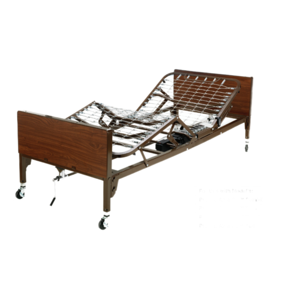
- Page 1 Protekt Akra Home Care Beds ™ User Manual & Entrapment Guide For Use with Model’s: Protekt Akra-SE™ Semi-Electric Bed, Spring Deck, Half Rails PMSEBHR Protekt Akra-SE™ Semi-Electric Bed, Spring Deck, Full Rails PMSEBFR Protekt Akra-FE™ Full-Electric Bed, Spring Deck, Half Rails PMFEBHR Protekt Akra-FE™...
- Page 2 User Manual & Entrapment Guide...
-
Page 3: Table Of Contents
Table Of Contents Special Notes ................. 4 Warnings ..................4 Bed Assembly ................5-10 Unpacking the Bed ..............5 Connecting the Two Frames ..........6-7 Connecting the Spring “Lattice” ..........8 Installing the Casters ..............9 Installing the Headboard and Footboard ....... 10 Bed Operation ................ -
Page 4: Special Notes
SPECIAL NOTES NOTICE: • The information contained in this document is subject to change without notice. • WARNINGS/CAUTION notices used in this manual apply to hazards or unsafe practices which could result in personal injury and/or property damage. • Check all parts for shipping damage and test before using. In case of a damage, do NOT use. -
Page 5: Bed Assembly
Bed Assembly Unpacking the Bed The Home Care Bed will arrive in two (2) boxes with the following contents: Box 1 of 2 includes: 1 Headboard 1 Footboard 1 Hand Crank (included with Semi-Electric model only) 4 Casters (2 locking, 2 non-locking) 4 Pins 1 Manual Box 2 of 2 includes:... -
Page 6: Connecting The Two Frames
Connecting the Two Frames Figure 1 Foot Section Head Section Figure 2 Figure 3 Connecting the Two Frames: 1. Place the Head Spring Section on its side to your left with the center mounting shaft to the right. (See figure 1) 2. - Page 7 6. After head and foot spring shafts are connected, insert locking pins and slowly open the frame sections into a horizontal (straight) position while still on their sides. Make sure the frame mounting shafts are locked in place with locking pins at all times. 7.
-
Page 8: Connecting The Spring "Lattice
Connecting the Spring “Lattice” Connecting the Spring “Lattice”: 1. With the bed flat and the springs facing up, lift the head spring section upward to give slack to the spring “lattice.” 2. Connect the spring “lattice” together with the links provided. 3. -
Page 9: Installing The Casters
Installing the Casters To Install Casters: Ensure that the locking casters are installed diagonally from each other and are locked. This will provide maximum locking security. 1. Position the two locking casters so they will be diagonally opposite from one another when the bed is assembled. -
Page 10: Installing The Headboard And Footboard
Installing the Headboard and Footboard CAUTION: Do not place your hand between the spring section and the bed ends while attaching the bed boards as injury may occur. To Attach the Head and Foot Boards: 1. Stand the headboard section as close to the head frame as possible. 2. -
Page 11: Bed Operation
Bed Operation Hand Control Pendant: Semi-Electric & Full-Electric Beds Semi-Electric Hand Pendant Full-Electric Hand Pendant BATTERY BACKUP In the event of the power failure, the standard 9 volt battery in the motor: Will allow the user to lower the head and foot sections of the bed. Will NOT allow the bed’s motor to lift the head or foot sections. -
Page 12: Installing The Electric Motor Unit
Installing the Electric Motor Unit Head/Foot Electric Motor Units 1. Before installing: Make sure that the hand pendant cable is plugged into the motor. 2. Connect the 9V battery (sold separately) to the battery clip on the motor. It is stored in the recess on the side of the motor. - Page 13 5. Full-Electric Bed Only - Insert the adapter into the clip. Aligning and Mounting the Motor 1. With the motor oriented properly underneath the bed (head to head, foot to foot), align the motor with actuator bar and lift the head spring to the highest position.
-
Page 14: Installing Drive Shaft Semi-Electric Bed
Installing Drive Shaft Semi-Electric Bed 1. Assemble the drive shaft as pictured in figures 1, 2, and 3. Figure 1 Figure 2 Figure 3 2. Attach 1 side of the drive shaft to the headboard gear box and the other end to the footboard gear box as pictured in figure 4. -
Page 15: Installing Drive Shaft Full-Electric Bed
Installing Drive Shaft Full-Electric Bed 1. Take 1 drive shaft and connect 1 end to the headboard gear box as pictured in figures 1, 2, and 3. Figure 1 Figure 2 Figure 3 2. Take 1 drive shaft and connect 1 end to the footboard gear box as pictured in above figures 1, 2, and 3. -
Page 16: Hand Crank For The Semi-Electric Bed
Hand Crank for the Semi- Electric Bed The manual bed crank is located at the foot of the bed. 1. Before attempting to manually adjust the bed height, it is necessary to remove the optional height adjustment lock pins from each leg. 2. -
Page 17: Bed Rail Installation
BED RAIL INSTALLATION Full Bed Rails: To install Full Bed Rails, lift the head section and find the rail receptacle located on the frame of the bed as shown (Fig A). Pull receptacle outward and return head section to the flat position. Turn receptacle in a vertical position to receive the rail (Fig B). -
Page 18: Maintenance And Safety Checks
MAINTENANCE AND SAFETY CHECKS To be performed once per year or between patient placements. Electronics Check all controls to make sure all functions work properly. • Power cord • Pendant cord • Check to make sure all wires are routed and attached properly so they do not interfere with any moving parts •... -
Page 19: Entrapment Guide
ENTRAPMENT GUIDE Bed Rails in Nursing Homes and the Home Health Care Environment KEY BODY PARTS AT RISK Three key body parts at risk for life-threatening entrapment in the seven zones of a hospital bed system discussed in this guidance are the head, neck, and chest. The body part dimensions used to develop FDA’s dimensional limit recommendations are summarized as follows: Key Body Part... -
Page 20: Potential Zones Of Entrapment
POTENTIAL ZONES OF ENTRAPMENT This guidance describes seven zones in the hospital bed system where there is a potential for patient entrapment. Entrapment may occur in flat or articulated bed positions, with the rails fully raised or in intermediate positions. The seven areas in the bed system where there is a potential for entrapment are identified in the drawing below. - Page 21 Zone 1 — Within the Rails This is any open space within the perimeter of the rail. Openings in the rail should be small enough to prevent the head from entering. A loosened bar or rail can change the size of the space. The HBSW and IEC recommend that the space be less than 120 mm (4-¾...
- Page 22 Zone 3 — Between the Rail and the Mattress This area is the space between the inside surface of the rail and the mattress compressed by the weight of a patient’s head. The space should be small enough to prevent head entrapment when taking into account the mattress compressibility, any lateral shift of the mattress or rail, and degree of play from loosened rails.
- Page 23 Zone 5, 6 and 7 Although seven potential zones of entrapment have been identified by HBSW, FDA is recommending dimensional limits for zones 1-4 because these zones were most frequently reported as having entrapments. FDA continues to receive entrapment reports for Zones 5 and 6, and Zone 7 remains a potential for entrapment FDA will monitor entrapments in these zones and consider harmonization with the IEC standard once it is available.
-
Page 24: A Guide To Bed Safety
Zone 7 — Between the Head or Foot Board and the End of the Mattress This is the space between the inside surface of the head board or foot board and the end of the mattress. This space may present a risk of head entrapment when taking into account the mattress compressibility, any shift of the mattress, and degree of play from loosened head or foot boards. -
Page 25: Protekt ® Home Care Beds Part List
The Benefits and Risks of Bed Rails Potential benefits of bed rails include: ● Aiding in turning and repositioning within the bed. ● Providing a hand-hold for getting into or out of bed. ● Providing a feeling of comfort and security. ●... -
Page 26: Meeting Patients' Needs For Safety
MEETING PATIENTS’ NEEDS FOR SAFETY Most patients can be in bed safely without bed rails. Consider the following: ● Use beds that can be raised and lowered close to the floor to accommodate both patient and health care worker needs. ●... - Page 27 Proactive Medical Products 270 Washington Street Mount Vernon, NY 10553 Tel: 855-237-7622 www.proactivemedical.com User Manual & Entrapment Guide...
Need help?
Do you have a question about the Protekt Akra PMSEBHR and is the answer not in the manual?
Questions and answers