Table of Contents
Advertisement
Quick Links
Advertisement
Table of Contents

Related Manuals for Proactive PROTEKT 33350


Summary of Contents for Proactive PROTEKT 33350
- Page 1 PROTEKT® ALL-IN-ONE UNIVERSAL PORTABLE ELECTRIC PATIENT LIFT M o d e l : 3 3 3 5 0 Ensure the product has been assembled according to the instructions in this manual. All operators should read and understand the instructions for safe and proper operation of the patient lift.
- Page 2 Thank you for choosing To better serve you, please record the following information for future use: Supplier Name: ___________________________________________ Supplier Telephone: ________________________________________ Product Serial Number: _____________________________________ Date of Purchase: _________________________________________...
-
Page 3: Product Description
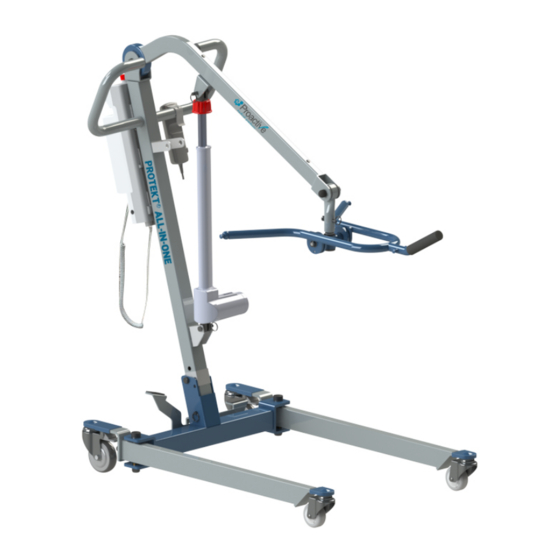
Product Description The Protekt® All-In-One 33350 allows the patient to be lifted and transferred safely with minimal physical effort provided by the operator. This is due to it being a full electric lift. The 33350 uses a special clip sling that will make transferring the patient more comfortable. -
Page 4: Definitions & Symbols
DEFINITIONS & SYMBOLS n this manual the user refers to the patient or resident and may be used interchangeably at different times. Caregiver refers to the operator or person who is assisting with the transfer. Symbols used in this manual and on the product and their meanings: Warning! Failure to heed this warning may Do Not Bleach. -
Page 5: Safety Instructions
Safety Instructions Protekt® All-In-One will provide years of service if it is properly maintained as any electric and/or mechanical equipment requires. Please pay careful attention to the following important information regarding the care, maintenance, and operation of the patient lift. Carefully read these instructions before assembling the lift, or attempting to lift a user with the device. - Page 6 WARNING! • NO equipment from its original state. This product is deemed safe to use with equipment may result in serious injury or death. • DO NOT replace any components of the lift without consulting with , and follow proper instruction from when replacing any components.
-
Page 7: Features And Overview
FEATURES & OVERVIEW • Prior to assembly, unpack and inspect all parts from the shipping carton. Contact your dealer immediately if any parts are damaged or missing. • Easy tools are provided to assist with initial set up. To ensure maximum safety, product should not be put into use until all connections are tightened using standard tools. - Page 8 33350 (in) A 1729.2 (68.1) B 1070.8 (42.2) 658.4 (25.9) 492.2 (19.4) 812.8 (32.0) 766.9 (30.2) 576.7 (22.7) 333.3 (13.1) 496.9 (19.6) 275 (10.8) 442.7 (17.4) 118.5 (4.7) 20.3 (0.8) N 1170.7 (46.1) 658.7 (25.9) 376.4 (14.8)
-
Page 9: Specifications And Options
Li� Weight Unloaded (lb) 94.2 55.7” Base Opened Turning Diameter 1414 mm Li� Weight Unloaded (kg) 42.8 51.2” Base Closed Turning Diameter 1300 * Proactive is committed to continuous improvements of our products therefore and are subject to change without prior notice. - Page 10 Step 1: Remove folded lift from box. Step 2: Secure the stand to the mast. Align the hole on the stand bracket with the lower hole on the mast. Make sure the tab on the stand bracket insert into top hole on the mast, and insert the screw to secure the stand bracket as follows.
- Page 11 Step 5: Insert the pin to secure the mast. Step 6: Remove the pin that is securing the boom. Step 7: Remove lower actuator pin on the mast. Step 8: Move the boom out of the way, and install the lower end of the actuator to the mast using a pin and retaining ring as follows.
- Page 12 Step 9: Install the upper end of actuator to the boom by reinserting the quick release pin to secure it. Step 10: Insert the spreader bar into the tube on the boom as follows. Align the holes and secure the spreader bar using a pin with wire lock.
- Page 13 M5 SCREWS M4 SCREWS...
- Page 14 Step 1: Remove The Spreader Bar WARNING: Step 2: Detach The Actuator...
- Page 15 Step 3: Fold Up The Boom Step 4: Fold Up The Mast...
- Page 16 Standing Up Lying Down...
- Page 17 Operating Instructions • -25°C to +5°C (-13°F to 41°F), and • +5°C to +35°C (41°F to 95°F) at a non-condensing relative humidity 0% to 90% • +35°C to +70°C at a water vapor pressure up to 5 kPa range: • at a temperature range of +5°C to +40°C (+41°F to +104°F) •...
- Page 18 Power Control Unit Overview Emergency Stop Button Up / Down Button Battery Pack Release Handle LCD Display Panel Battery Pack Charger DC In Not Used Additional Battery Pack (Optional) Charging Cradle Actuator (Optional) Hand Control 1. Connect Actuator as shown above. 2.
- Page 19 Pressed In Release LCD Display Panel Signs When the emergency stop button is released, the LCD Display Panel will show one of the four signs below. • The sign will display for 5 seconds. • Then the lift will go into standby mode and the sign disappears. •...
- Page 20 Operating Lift: Using Hand Control LED Indicator Lifting * Green = In Use * Blank = Standby Lowering Operating Lift: Using LCD Display Panel...
- Page 21 Warning! - Battery Low and Charging is Needed If the battery needs to be charged, the LCD Display Panel will show a blinking low battery sign shown on the left either when the emergency stop button is released or when a button on the LCD Display Panel is pressed.
- Page 22 Protekt® All-In-One Slings 30502 General Purpose Clip Sling w/ Padded Legs, Polyester - Medium (MAA4000M-M) General Purpose Clip Sling w/ Padded Legs, Polyester - Large (MAA4000M-L) 30503 30504 General Purpose Clip Sling w/ Padded Legs, Polyester - XLarge (MAA4000M-XL)
- Page 23 Sling Hook Sling Clip • Slide the clip over the sling hook on the spreader bar through the hole • Pull down the clip to lock the sling on to the spreader Hook up A Point 1 Hook up B Point 2 Hook up C Point 3...
- Page 24 1. User/patient should be in the center of the bed. 2. Position user onto his/her side by rolling user towards you. 3. Roll the sling in half. The handle on the back section sling should face outward when 4. Position the sling under the user/patient so the commode aperture aligns with the base of the spine and top of the sling close to the neck.
- Page 25 1. Help the user lean forward slightly, then slide the sling down between the car seat and the user’s back. 2. Position the sling equally around both sides of the body. 3. Draw the leg sections to the front along the length of the user’s thigh. 4.
-
Page 26: Maintenance And Inspection
Maintenance & Inspection • The Proactive Lift requires a minimum of service to keep it in proper working order and to assure safe operation. It is important that certain basic checks be performed periodically • The manufacturer recommends that the following components and operating points manufacturer also recommends visual inspection prior to use for the additional points below (V). -
Page 27: Cleaning And Disinfecting
Cleaning and Disinfecting • Use pH-neutral detergents only. • Remove the battery from the controller • Clean lift surfaces, control box and hand control with a damp cloth using pH- neutral detergent. • Remove debris and hair from the casters and make sure the casters can spin and swivel freely. -
Page 28: Troubleshooting Guide
Troubleshooting Guide The following list of encountered problems and solutions will assist you in determining what may be causing your patient lift not to function as designed. If you have a problem occurring which is not listed below please contact your dealer or technical support for help. Do not attempt to repair or replace components or parts on your lift as this may void your warranty or cause further problems that may result in patient injury. - Page 29 Emergency Lowering Mechanism In case of lift failure, please follow the procedures below to safely lower the user. The Emergency Lowering Device is located at the top of the actuator shaft. It is intended for use if the actuator or electronics fail to operate while the patient is suspended in midair. wise continually until the patient has been lowered.
- Page 30 WARRANTY POLICY All-In-One...
- Page 31 .com...
Need help?
Do you have a question about the PROTEKT 33350 and is the answer not in the manual?
Questions and answers