Table of Contents
Advertisement
Quick Links
Advertisement
Table of Contents

Subscribe to Our Youtube Channel
Related Manuals for Winmate Military Series


Summary of Contents for Winmate Military Series
- Page 1 15”/ 17”/ 19”/ 21.5”/ 23.8”/ 32” Console Rack Panel PC Intel® Core™ i5 -1135G7 2.4 GHz (turbo to 4.2 GHz) Military Series R15IT3S-MLA3FP Model No. R17IT3S-MLA1FP R19IT3S-MLA3FP W22IT3S-MLA3FP W24IT3S-MLA2FP W32IT3S-MLA3FP User Manual Version 1.0 Document Part No. 91521110111I...
-
Page 2: Table Of Contents
Military Console Rack PCAP Panel PC User Manual Contents Preface ............................3 About This User Manual ......................6 Chapter 1: Introduction ......................... 6 1.1 Overview ......................... 7 1.2 Product Features ......................7 1.3 Package Contents ......................8 1.4 Appearance ........................8 1.5 Connector Description ..................... - Page 3 Preface 3.2.6 Exit ........................42 Chapter 4: Technical Support ..................... 43 4.1 Software Developer Support ..................43 4.2 Problem Report Form ....................43 Appendix............................44 Appendix A: Technical Specifications.................. 44 Appendix B: Military Grade Compliance ................46 Appendix C: Maintenance ....................47 Appendix D: Serial Port Settings ..................
-
Page 4: Preface
Military Console Rack PCAP Panel PC User Manual Preface Copyright Notice No part of this document may be reproduced, copied, translated, or transmitted in any form or by any means, electronic or mechanical, for any purpose, without the prior written permission of the original manufacturer. - Page 5 Preface Federal Communications Commission Radio Frequency Interface Statement This device complies with part 15 FCC rules. Operation is subject to the following two conditions: This device may not cause harmful interference. This device must accept any interference received including interference ...
- Page 6 Military Console Rack PCAP Panel PC User Manual Advisory Conventions Four types of advisories are used throughout the user manual to provide helpful information or to alert you to the potential for hardware damage or personal injury. These are Notes, Important, Cautions, and Warnings.
-
Page 7: About This User Manual
Chapter 1: Introduction PRECAUTIONS • Do not use the monitor near water. • Do not place the monitor on an unstable cart, stand, or table. If the monitor falls, it can injure a person and cause serious damage to the appliance. Use only a cart or stand recommended by the manufacturer or sold with the monitor. -
Page 8: Overview
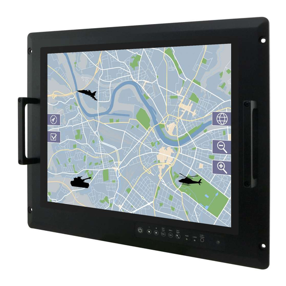
Military Console Rack PCAP Panel PC User Manual 1.1 Overview Congratulations on purchasing Winmate® Military Console Rack Panel PC. Winmate's military series of console rack Panel PCs are durable PCs that have undergone rigorous testing to ensure safety and performance that goes beyond standard military compliance. These PCs include MIL- DTL-38999 type I connectors and are built to survive drops, shocks, liquid spills, vibrations, dust and extreme temperatures;... -
Page 9: Package Contents
Chapter 1: Introduction 1.3 Package Contents Carefully remove the box and unpack your display. Please check if all the items listed below are inside your package. If any of these items are missing or damaged contact us immediately. Standard package includes: ... -
Page 10: Connector Description
Military Console Rack PCAP Panel PC User Manual 1.5 Connector Description The I/O connectors are located on the bottom rear side of the panel PC. Item Description Function Power input AC 110~240V (Default) or DC 9~36V Power input connector (Optional). Provides serial communication transmission of Serial port RS-232/422/485 data RS-232/422/485. -
Page 11: Panel Controls
Chapter 1: Introduction 1.6 Panel Controls Panel controls are located on the front side of the display. On-Screen Display (OSD) is a user- friendly interface to remote the display function and to adjust the display’s image properties. It also supports special Hot Keys for easy control, such as auto-adjustment and brightness control for backlight. -
Page 12: Dimensions
Military Console Rack PCAP Panel PC User Manual 1.7 Dimensions 15-inch Panel PC, R15IT3S-MLA3FP Unit: mm Dimensions: 402 x 321 x 70 17-inch Panel PC, R17IT3S-MLA1FP Unit: mm 482.6 x 399.3 x 79.6 Dimensions:... - Page 13 Chapter 1: Introduction 19-inch Panel PC, R19IT3S-MLA3FP Unit: mm Dimensions: 482.6 x 399.3 x 81.4 21.5-inch Panel PC, W22IT3S-MLA3FP Unit: mm Dimensions: 580 x 384 x 71...
- Page 14 Military Console Rack PCAP Panel PC User Manual 23.8-inch Panel PC, W24IT3S-MLA2FP Unit: mm Dimensions: 635.2 x 430.9 x 66 32-inch Panel PC, W32IT3S-MLA3FP Unit: mm Dimensions: 825 x 500 x 87.2...
-
Page 15: Chapter 2: Installation
Chapter 2: Installation Chapter 2: Installation This chapter provides hardware installation instructions and mounting guide for all available mounting options. Pay attention to cautions and warning to avoid any damages 2.1 Wiring Requirements The following common safety precautions should be observed before installing any electronic device: ... -
Page 16: Mounting The Device
Military Console Rack PCAP Panel PC User Manual 2.2 Mounting the Device The Military Panel PC supports different mounting options. Refer to sub-sections below for more details. 2.2.1 Panel Mount The main mounting approach for military applications is panel mount - very user-friendly in terms of installation. -
Page 17: Vesa Mount
3. Place the device on VESA bracket. 4. Follow instructions supplied with your mounting kit. 5. Connect cables, power on the panel PC. VESA Mount Installation *Notice that VESA stand and mounting kit are not provided by Winmate. Size VESA Plate Screw Size 15”... -
Page 18: Powering On
Military Console Rack PCAP Panel PC User Manual 2.3 Powering On Follow the recommendations below when powering on the equipment. Plug-in the power cord to easy accessible AC outlet. Plug-in the AC adapter to a grounded outlet. Earth Ground! This product must be grounded. -
Page 19: Connecting To Dc Input Power Source (Optional)
Chapter 2: Installation Connector Pinouts: Pin № Signal Name VCC+ VCC- 2.3.2 Connecting to DC Input Power Source (Optional) DC Power Input Requirements: 9~36V DC. 1. Insert the exposed wires of the DC Power Cable to the appropriate connectors on the terminal block plug. -
Page 20: Connecting Other Devices
Military Console Rack PCAP Panel PC User Manual 2.4 Connecting Other Devices Use serial cable, USB and HDMI cables to connect your panel PC to external device. Caution Observe all local installation requirements for connection cable type and protection level. Attention Suivre tous les règlements locaux d’installations, de câblage et niveaux de protection. -
Page 21: Lan1/ Lan2: Gigabit Ethernet
Chapter 2: Installation 2.4.3 LAN1/ LAN2: Gigabit Ethernet The panel PC has two RJ-45 Gigabit Ethernet connectors to connect your device to Ethernet. Pin assignment and signal names of Pin № Pin № Name Name RJ45 connector TX1+ TX1- TX2+ TX3+ TX3- TX2-... -
Page 22: How To Enable Watchdog
2.6 How to Enable Watchdog To enable Watchdog, you need to download Winmate Watchdog utility. Find more information on Watchdog in “Watchdog Guide” that you can download from Winmate Download Center or File Share. Refer to the User Manual for more details. -
Page 23: Using Recovery Wizard To Restore Computer
Chapter 2: Installation 2.7 Using Recovery Wizard to Restore Computer Note: Before starting the recovery process, make sure to backup all user data. The data will be lost after the recovery process. Important: Before starting the recovery process, remove the PCI/ PCIe card and CFast card (If equipped). -
Page 24: Chapter 3: Bios Setup
Military Console Rack PCAP Panel PC User Manual Chapter 3: BIOS Setup This chapter describes the different settings available in the INSYDE BIOS that comes with the board. 3.1 How and When to Use BIOS Setup To enter the BIOS setup, you need to connect an external USB keyboard, external monitor and press Del key when the prompt appears on the screen during start up. -
Page 25: Bios Functions
Chapter 3: BIOS Setup 3.2 BIOS Functions 3.2.1 Main Menu The Main menu displays the basic information about your system including BIOS version, processor RC version, system language, time, and date. When you enter BIOS setup, the first menu that appears on the screen is the main menu.It contains the system information including BIOS version, processor RC version, system language, time, and date. -
Page 26: Advanced
Military Console Rack PCAP Panel PC User Manual 3.2.2 Advanced Select the Advanced Tab from the setup menu to enter the advanced BIOS setup screen. You can select any of the items on the left frame of the screen to go to the sub menu for the item, such as CPU Configuration. - Page 27 Chapter 3: BIOS Setup 3.2.2.1 CPU Configuration BIOS Setting Description Setting Option Effect Intel (VMX) Enable or disable Intel Enable/Disable When enabled, a VMM Virtualization Virtualization can utilize the Technology Technology. additional hardware capabilities provided by Vanderpool Technology. Active Processor Number of core to AII / 1 / 2/ 3 Select number of core...
- Page 28 Military Console Rack PCAP Panel PC User Manual 3.2.2.2 F81886A Configuration .2.2.3 GPIO Configuration...
- Page 29 Chapter 3: BIOS Setup 3.2.2.4 Hardware Monitor...
- Page 30 Military Console Rack PCAP Panel PC User Manual 3.2.2.5 PCH-IO Configuration BIOS Setting Description Setting Option Effect PCI Express PCI Express clock gating Enter Opens sub-menu Configuration enable/disable for each root port. SATA And RST Enable/ Disable SATA device Enter Opens sub-menu Configuratuion Selectively enable/ disable...
- Page 31 Chapter 3: BIOS Setup 3.2.2.6 PCI Express Configuration...
- Page 32 Military Console Rack PCAP Panel PC User Manual 3.2.2.7 SATA and RST Configuration 3.2.2.8 USB Configuration...
- Page 33 Chapter 3: BIOS Setup 3.2.2.9 ME Firmware Configuration 3.2.2.10 Power & Performance BIOS Setting Description Setting Option Effect CPU – Power Configure CPU – Power Enter Opens sub- Management Control Management parameters menu...
- Page 34 Military Console Rack PCAP Panel PC User Manual BIOS Setting Description Setting Option Effect Boot Configure Boot -Max non-turbo Select the performance state that Performance Performance Mode performance the BIOS will set starting from Mode parameters -Max battery reset vector -Turbo Performance Intel...
- Page 35 Chapter 3: BIOS Setup 3.2.2.11 System Agent (SA) Configuration BIOS Setting Description Setting Option Effect Graphics Configure Graphics Enter Opens sub-menu Configuration Configuration parameters Vt-d Intel® Virtualization Enabled Vt-d capability Technology for Disabled Directed I/O...
- Page 36 Military Console Rack PCAP Panel PC User Manual 3.2.2.11.1 Graphics Configuration BIOS Setting Description Setting Option Effect Internal Graphics Internal Graphics Auto Keep IGFX enabled based on settings Enabled the setup options Disabled Aperture Size Select the 128MB Select the aperture size Note: Above 4MB MMIO BIOS aperture size 256MB...
- Page 37 Chapter 3: BIOS Setup 3.2.2.7.2 Vt-d BIOS Setting Description Setting Option Effect Vt-d Intel® Virtualization Enabled Vt-d capability Technology for Disabled Directed I/O...
-
Page 38: Boot
Military Console Rack PCAP Panel PC User Manual 3.2.3 Boot BIOS Setting Description Setting Option Effect UEFI Boot Type Select boot type to Dual type, Boot Type Boot Type Legacy type or UEFI type configuration Enabled Allows InsydeH20 to skip certain Quick Boot Quick Boot Disabled... - Page 39 Chapter 3: BIOS Setup 3.2.3.1 Boot Type Order BIOS Setting Description Setting Option Effect Enter Opens Sub-menu Hard Disk Type Hard Disk Type configuration Enter Opens Sub-menu Others Other configuration...
- Page 40 Military Console Rack PCAP Panel PC User Manual 3.2.3.2 Others...
-
Page 41: Security
Chapter 3: BIOS Setup 3.2.4 Security BIOS Setting Description Setting Option Effect TrEE Protovol TrEE Protocol Choose TrEE Version: 1.0 or 1.1 Version Protocol Version Available When hidden don’t TPM Availability TPM Availability Hidden exposes TPM to 0 configuration Select one of the TPM Operation TPM Operation supported operation... -
Page 42: Power
Military Console Rack PCAP Panel PC User Manual 3.2.5 Power BIOS Setting Description Setting Option Effect Disabled Enable/ Disable ACPI ACPI S3 ACPI S3 Enabled S1/S3 Sleep state configuration Disabled Auto Wake on S5 Auto Wake on S5 Auto Wake on S5, by By Every Day configuration Day or Month or fixed... -
Page 43: Exit
Chapter 3: BIOS Setup 3.2.6 Exit... -
Page 44: Chapter 4: Technical Support
4.1 Software Developer Support We provide the SDK in the User Manual and SDK CD, or you can download the SDK from Winmate Download Center. The list of SDK for Rack Mount Pnael PC: Item Type... -
Page 45: Appendix
Appendix This chapter contains additional product information, including troubleshooting guide and frequency table Appendix A: Technical Specifications This section includes product technical specifications. Model R15IT3S- R17IT3S- R19IT3S- W22IT3S- W24IT3S- W32IT3S- Name MLA3FP MLA1FP MLA3FP MLA3FP MLA2FP MLA3FP Display Size 15.0 inches 17.0 inches 19.0 inches 21.5 inches... - Page 46 Environment Operating 10% to 95% 10% to 95% 10% to 95% 10% to 95% 10% to 95% 10% to 95% Humidity Operating 20°C~60°C 20°C~60°C 20°C~60°C 20°C~60°C 20°C~60°C 20°C~60°C Temp. Storage 30°C~70°C 30°C~70°C 30°C~70°C 30°C~70°C 30°C~70°C 30°C~70°C Temp. IO Ports 2 x USB 3.2 2 x USB 3.2 2 x USB 3.2 2 x USB 3.2...
-
Page 47: Appendix B: Military Grade Compliance
Accessory 1 x Manual 1 x Manual 1 x Manual 1 x Manual 1 x Manual 1 x Manual (Hardcopy), (Hardcopy), (Hardcopy), (Hardcopy), (Hardcopy), (Hardcopy), 1 x Driver CD, 1 x Driver CD, 1 x Driver CD, 1 x Driver CD, 1 x Driver CD, 1 x Driver CD, Accessory... -
Page 48: Appendix C: Maintenance
Appendix C: Maintenance This equipment is extremely rugged and does not require a lot of maintenance. Remember that electrical equipment should be handled with care and used accordingly to its specifications. Cleaning the Display Screen Wipe the screen with a clean, soft, lint-free cloth. This removes dust and other particles. Do not use acetone, ethyl alcohol, toluene, ethyl acid or methyl chloride to clear the panel. -
Page 49: Appendix D: Serial Port Settings
Appendix D: Serial Port Settings To change serial port settings, enter the BIOS setup menu by pressing DEL key during POST. Go to Advanced => PCH-FW Configuration > Serial Port... - Page 50 Notes ______________________________________________________________________________ ______________________________________________________________________________ ______________________________________________________________________________ ______________________________________________________________________________ ______________________________________________________________________________ ______________________________________________________________________________ ______________________________________________________________________________ ______________________________________________________________________________ ______________________________________________________________________________ ______________________________________________________________________________ ______________________________________________________________________________ ______________________________________________________________________________ ______________________________________________________________________________ ______________________________________________________________________________ ______________________________________________________________________________ ______________________________________________________________________________ ______________________________________________________________________________ ______________________________________________________________________________ ______________________________________________________________________________ ______________________________________________________________________________ ______________________________________________________________________________ ______________________________________________________________________________ ______________________________________________________________________________ ______________________________________________________________________________ ______________________________________________________________________________ ______________________________________________________________________________ ______________________________________________________________________________ ______________________________________________________________________________ ______________________________________________________________________________ ______________________________________________________________________________ ______________________________________________________________________________ ______________________________________________________________________________ ______________________________________________________________________________ ______________________________________________________________________________ ______________________________________________________________________________ ______________________________________________________________________________ ______________________________________________________________________________ ______________________________________________________________________________ ______________________________________________________________________________ ______________________________________________________________________________ ______________________________________________________________________________ ______________________________________________________________________________...
- Page 51 Notes ______________________________________________________________________________ ______________________________________________________________________________ ______________________________________________________________________________ ______________________________________________________________________________ ______________________________________________________________________________ ______________________________________________________________________________ ______________________________________________________________________________ ______________________________________________________________________________ ______________________________________________________________________________ ______________________________________________________________________________ ______________________________________________________________________________ ______________________________________________________________________________ ______________________________________________________________________________ ______________________________________________________________________________ ______________________________________________________________________________ ______________________________________________________________________________ ______________________________________________________________________________ ______________________________________________________________________________ ______________________________________________________________________________ ______________________________________________________________________________ ______________________________________________________________________________ ______________________________________________________________________________ ______________________________________________________________________________ ______________________________________________________________________________ ______________________________________________________________________________ ______________________________________________________________________________ ______________________________________________________________________________ ______________________________________________________________________________ ______________________________________________________________________________ ______________________________________________________________________________ ______________________________________________________________________________ ______________________________________________________________________________ ______________________________________________________________________________ ______________________________________________________________________________ ______________________________________________________________________________ ______________________________________________________________________________ ______________________________________________________________________________ ______________________________________________________________________________ ______________________________________________________________________________ ______________________________________________________________________________ ______________________________________________________________________________ ______________________________________________________________________________...
- Page 52 Winmate Inc. 9F, No.111-6, Shing-De Rd., San-Chung District, New Taipei City 24158, Taiwan, R.O.C www.winmate.com Copyright © 2023 Winmate Inc. All rights reserved.
Need help?
Do you have a question about the Military Series and is the answer not in the manual?
Questions and answers