
Related Manuals for Motorola solutions PELCO Ulisse Enhanced PTZ 2 Series


Summary of Contents for Motorola solutions PELCO Ulisse Enhanced PTZ 2 Series
- Page 1 ENGLISH Ulisse Enhanced PTZ 2 Series Installation manual Document number: MNLCU240X_2344 Publication date: 01/24...
-
Page 3: Table Of Contents
Contents E N G L I S H 1 About this manual ........................5 1.1 Typographical conventions ..............................5 2 Notes on copyright and information on trademarks ............5 3 Safety rules ..........................5 4 Legal notices ..........................7 5 Identification ..........................8 5.1 Product overview ................................... - Page 4 8.9.5 Inserting an SD Card ....................................20 8.10 Housing closure ..................................20 9 Switching on ........................... 21 10 Configuration........................21 10.1 Default IP address ................................21 10.2 Web interface ..................................21 10.2.1 First access to the web pages .................................21 10.3 Camera configuration ..............................21 11 Instructions for normal operation ..................
-
Page 5: About This Manual
1 About this manual 3 Safety rules Read all the documentation supplied carefully CAUTION! The electrical system to which before installing and using this product. Keep the the unit is connected must be equipped manual in a convenient place for future reference. with a 10A max automatic bipolar circuit breaker. - Page 6 • The product is designed to house only cameras CAUTION! In order to reduce the risk of that are properly certified. fire, only use UL Listed or CSA certified • A power disconnect device must be included cables with sections greater than or equal in the electrical installation, and it must be very to 0.14mm²...
-
Page 7: Legal Notices
4 Legal notices • The device must be properly connected to the earth circuit. © 2023, Pelco Corporation. All rights reserved. • The equipment is intended for installation in a Covered by one or more claims of the patents listed Restricted Access Area by specialist technical staff. -
Page 8: Identification
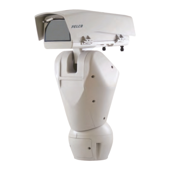
5 Identification 5.2 Product marking label 5.1 Product overview The product has a label compliant with CE marking. The main parts of the product are illustrated below: Sunshield. Body. Base. Fig. 2 The label shows: • Model identification code (Extended 3/9 bar code). -
Page 9: Preparing The Product For Use
6 Preparing the product for 6.3 Contents Check the contents to make sure they correspond with the list of materials as below: Any change that is not expressly approved • Positioning unit by the manufacturer will invalidate the • Power supply base warranty. -
Page 10: Preparatory Work Before Installation
7 Assembly 6.5 Preparatory work before installation 7.1 Sunshield mounting 6.5.1 Mounting the bracket Fix the sunshield to the housing using the screws Different types of supports are available (12 and washers screwed into the upper body of the Accessories, page 22). Choose a suitable bracket for housing. -
Page 11: Installation
8 Installation Open the hatch by undoing the screws as shown in figure. Insert the cables into the cable glands holding the Never, under any circumstances, make base at about 20cm from the support. any changes or connections that are not shown in this handbook. -
Page 12: Connecting The Pan & Tilt To The System
8.2 Connecting the Pan & Tilt to Once you have positioned the gasket (01), fix the base (02) onto the bracket (03) with screws (04), the system serrated washers (05) and screw rings (06). 8.2.1 Connector board description BOARD DESCRIPTION Components Function Power supply line... -
Page 13: Installing Cable Ferrites
8.3 Installing cable ferrites Cut the cables to the correct length and make the connections. Connect the power supply to the Install the supplied ferrites on each cable as shown connector. in the figure. The power supply cable must be covered by the silicone sheath (01) supplied. -
Page 14: I/O Cable Connection
8.3.3 I/O cable connection CONNECTION OF THE ALARM INPUTS, OF THE TWILIGHT SWITCH AND OF THE RELAYS All signal cables must be grouped together Terminals Description by means of a cable tie. Shielded cable sleeve RL1A, RL1B, Dry output contacts, can be activated by alarm RL2A, RL2B or by user control AL1, AL2, AL3,... -
Page 15: Description Of The Factory Default Procedure
8.5 Fixing the upper body 8.3.4 Description of the Factory Default procedure Place the unit body on the base aligning the If the access password is no longer available, follow reference marks. Insert the unit body anti-tipping the procedure to reset to default factory settings. columns in the holes on the base. -
Page 16: Led Illuminators Installation (Optional Features)
8.6 LED illuminators installation 8.6.2 Fitting the illuminator on the bracket (optional features) Place the fixings of the illuminator (01) on those of the bracket (02). To work properly both illuminators must be installed together. From Pan & Tilt, it is only possible to install UPTIRN illuminators. -
Page 17: Housing Opening
8.6.3 Housing opening BOARD DESCRIPTION Loosen the 2 screws on the side, turn the cover and Compo- Function nent the upper half of the body about the opening hinge axis. Camera power supply, camera input alarm, camera output alarm Power supply and control (Primary illuminator) Heated glass Wiper Ethernet... -
Page 18: Connection Of The Led Illuminators
8.8 Connection of the LED 8.9 LED illuminator activation illuminators and adjustment instructions Open the housing as described in the relative The two illuminators can be controlled in different chapter (8.6.3 Housing opening, page 17). ways depending to the unit configuration (10.3 Camera configuration, page 21). -
Page 19: Led Illuminator Switching On Threshold Adjustment
8.9.1 LED illuminator switching on 8.9.2 LED illuminator power adjustment threshold adjustment The illuminator is set in the factory to provide maximum power. If you don't need to illuminate distant subjects or if the image is over-exposed for excessive brightness, decrease the power, so that energy saving is also obtained. -
Page 20: Activation Of The Led Illuminator Via An External Dusk Switch
8.9.3 Activation of the LED illuminator • Adjust the Spot illuminator settings: via an external dusk switch • Lighting threshold: Set the value to OFF. • Power supplied: Set the value as needed (from The LED illuminators are activated by an external 50% to 100%). -
Page 21: Switching On
9 Switching on 10.2 Web interface 10.2.1 First access to the web pages Ensure the unit and the other components of the system are appropriately closed to The first operation in configuring the device consists prevent contact with live parts. in connecting to the web interface. -
Page 22: Accessories
12 Accessories 12.2 Mounting bracket for LED illuminators For further details on configuration and use, refer to the relative manual. A mounting bracket is necessary to install the Pelco LED illuminators. 12.1 Washer The product can be equipped with an external pump that provides water to clean the glass. -
Page 23: Wall Mount Bracket
13 Maintenance 12.4 Wall mount bracket Wall bracket with internal cable channel. Before doing any technical work on the device, disconnect the power supply. CAUTION! Device installation and maintaining must be performed by specialist technical staff only. If contacting the Pelco technical service or the authorized support centre, you must provide the product serial number (5.2 Product marking label, page 8). -
Page 24: Cleaning
14 Cleaning 16 Troubleshooting 14.1 Cleaning the window and Contact the Pelco technical service or an authorized support centre if the problems plastic parts listed below persist or you have any other issues that are not described here. Avoid ethyl alcohol, solvents, hydrogenated hydrocarbide, strong acid PROBLEM The product does not turn... -
Page 25: Technical Drawings
17 Technical drawings The indicated measurements are expressed in millimetres. 258[10.16] 532[20.9] Fig. 35 Ulisse Enhanced PTZ 2 Series. MNLCU240X_2344... - Page 26 496[19.5] 258[10.16] 532[20.94] Fig. 36 Ulisse Enhanced PTZ 2 Series, version with two LED illuminators. Pelco, Inc. 625 W. Alluvial Ave., Fresno, California 93711 United States (800) 289-9100 Tel (800) 289-9150 Fax +1 (559) 292-1981 International Tel +1 (559) 348-1120 International Fax www.pelco.com Pelco, the Pelco logo, and other trademarks associated with Pelco products referred to in this publication are trademarks of Pelco, Inc.
Need help?
Do you have a question about the PELCO Ulisse Enhanced PTZ 2 Series and is the answer not in the manual?
Questions and answers