
Subscribe to Our Youtube Channel
Related Manuals for Motorola solutions PELCO EXSITE PRO PTZ Series


Summary of Contents for Motorola solutions PELCO EXSITE PRO PTZ Series
- Page 1 EXSITE® PRO PTZ SERIES Installation Manual Document number: MNLCEXPRO_2305 Publication date: 05/23...
-
Page 2: Table Of Contents
EXSITE® PRO PTZ SERIES Installation Manual Table of Content About this manual Typographical conventions Notes on copyright and information on trademarks Safety Safety rules for hazardous environment Safety rules Product description and type designation Range of use Specific use conditions Gas Group, Dust Group and Temperatures Characteristics of installable devices Cable entry... - Page 3 EXSITE® PRO PTZ SERIES Installation Manual Relays RL1 connection Washing system connection Integrated power supply connection External power supply connection Washer installatiom Ethernet connection Connection via RJ45 Connection via SFP Junction box closing Screws properties Washers DIN 127 B properties: Washers ISO 7089 properties: Switching on Configuration...
-
Page 4: About This Manual
EXSITE® PRO PTZ SERIES Installation Manual About this manual Read all the documentation supplied carefully before installing and using this device. Keep the manual in a convenient place for future reference. Typographical conventions Danger:Explosion hazard. Read carefully to avoid danger of explosion. Danger:High level hazard. -
Page 5: Safety Rules
EXSITE® PRO PTZ SERIES Installation Manual Danger: Risk of explosion due to electrostatic discharge. The device is intended for fixed installation and the user shall not frequently touch the device in service (other than maintenance). Take suitable measures to ensure that no electrostatic discharges can build up in the classified area. - Page 6 EXSITE® PRO PTZ SERIES Installation Manual Check that the power supply socket and cable are adequately dimensioned. Use suitable cables that can withstand the operating temperatures. All disconnected cables must be electrically isolated. Danger: Mechanical hazard. Risk of crushing or shearing. Hazardous moving parts.
-
Page 7: Product Description And Type Designation
EXSITE® PRO PTZ SERIES Installation Manual Only use original manufacturer spare parts. Strictly adhere to the maintenance instructions attached to each replacement kit. Since the user is responsible for choosing the surface to which the unit is to be anchored, we do not supply the fixing devices for attaching the unit firmly to the particular surface. -
Page 8: Specific Use Conditions
EXSITE® PRO PTZ SERIES Installation Manual Specific use conditions Contact the manufacturer for information on the dimensions of the flameproof joint. Ambient temperature and Surface temperature. See installation instructions. Take care to prevent accumulation of electrostatic charges. See installation instructions. The device can be installed in standard or inverted positions only . -
Page 9: Variants
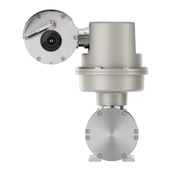
EXSITE® PRO PTZ SERIES Installation Manual Variants Product overview The product consists of the following parts: 1. Sunshield/s. 2. Housing/s. 3. Body. 4. Junction box. Figure 1: EXSITE® PRO PTZ SERIES overview. Day/Night camera Figure 2: EXSITE® PRO PTZ SERIES EXPP1. MNLCEXPRO_2305 | 05/23... -
Page 10: Day/Night Camera And Led Illuminator
EXSITE® PRO PTZ SERIES Installation Manual Day/Night camera and LED illuminator Figure 3: EXSITE® PRO PTZ SERIES EXLP1. Product marking label Figure 4: Product marking label. MNLCEXPRO_2305 | 05/23... -
Page 11: Requirements For The Ul/Csa Standard
EXSITE® PRO PTZ SERIES Installation Manual The following information must all be present but may be arranged differently from the images in this document 1. Trademark 2. Manufacturer's name and address. 3. Model. 4. The serial number consists of 12 numeric characters, the second and third digits define the last two numbers of the year of manufacture. - Page 12 EXSITE® PRO PTZ SERIES Installation Manual Figure 5: Warning label. In the USA, the National Electrical Code (NEC) and in Canada the Canadian Electrical Code (CEC) apply to electrical equipment used on hazardous industrial premises. Important safety instructions DO NOT OPEN WHEN AN EXPLOSIVE ATMOSPHERE IS PRESENT. NE PAS OUVRIR EN PRÈSENCE D'UNE ATMOSPHÉRE EXPLOSIVE.
-
Page 13: Model Identification
EXSITE® PRO PTZ SERIES Installation Manual Model identification Day/Night camera EXPP- CERTIFICATIONS AND MARKING Certification Marking Ambient temperature Cable entry temperature Ex II 2G Ex db IIB+H2 T5 Gb UL 23 ATEX -40°C ≤ Ta ≤ +70°C +81°C 3004X Ex II 2D Ex tb IIIC T100°C Db Ex II 2G Ex db IIC T6 Gb -40°C ≤... -
Page 14: Day/Night Camera And Led Illuminator
EXSITE® PRO PTZ SERIES Installation Manual Table 1: EXSITE® PRO PTZ SERIES (EXPP) - CERTIFICATIONS AND MARKINGS. Day/Night camera and LED illuminator EXPL- CERTIFICATIONS AND MARKING Certification Marking Ambient temperature Cable entry temperature Ex II 2G Ex db IIB+H2 T5 Gb UL 23 ATEX -40°C ≤... -
Page 15: Preparing The Product For Use
EXSITE® PRO PTZ SERIES Installation Manual Table 2: EXSITE® PRO PTZ SERIES (EXLP) - CERTIFICATIONS AND MARKINGS. Preparing the product for use Before carrying out any type of maintenance, read the "Safety rules" chapter carefully in the product manual. Unpacking When the product is delivered, make sure that the package is intact and that there are no signs that it has been dropped or scratched. -
Page 16: Sunshield Mounting
EXSITE® PRO PTZ SERIES Installation Manual Figure 6: Installation options for all versions. The housing has two position for sunshield: one for standard position and one for inverted position (ceiling mount). Sunshield mounting Remove the protective film before the sunshield installation (if present). Fix the sunshield to the housing using the screws and spacers (provided) into the upper body of the housing. -
Page 17: Opening Of The Junction Box
EXSITE® PRO PTZ SERIES Installation Manual Screw head: ISO 4762 Length: 8mm (0.3in) Yield stress: 450N/mm² Figure 8: Equipotential bonding connection. Washers DIN 6798 properties: Diameter: 5mm Material: A4 Opening of the junction box During opening and closure operations of the product, pay attention not to damage the flameproof joint. -
Page 18: Connector Board Description
EXSITE® PRO PTZ SERIES Installation Manual Figure 9: Opening of the junction box. Connector board description BOARD DESCRIPTION Function Connector Terminals - Nominal section of the cables used Power supply line from 0.2mm² (24AWG) up to 2.5mm² (13AWG) Alarms, Remote reset and Relays from 0.2mm²... -
Page 19: Connection Of The Safety Earthing
EXSITE® PRO PTZ SERIES Installation Manual Table 3: Connector board description. Figure 10: Connector board. Connection of the safety earthing The safety earth cable must be about 10mm longer than the other two power supply cables, so that it cannot be accidentally disconnected if pulled. The safety earth cable section must be equal or greater than the section of the power supply cables. -
Page 20: Connecting The Power Supply (From 100Vac Up To 240Vac)
EXSITE® PRO PTZ SERIES Installation Manual Figure 11: Connection compartment. Extract the removable power line connector from the connector board (J1, Connector board description). Connect the electrical power cables as indicated in the relevant table (BOARD DESCRIPTION). Check that the power supply socket and cable are adequately dimensioned. Connect the removable power line connector to the connector board (J1, Connector board description). -
Page 21: Connecting An Alarm With Dry Contact
EXSITE® PRO PTZ SERIES Installation Manual CONNECTION OF THE ALARM INPUTS AND RELAYS Connector Terminals Function Technical data AL1, COM Auto-powered from 12Vdc up Self-powered alarm input fitted in the to 18Vdc 200m max common terminal RST, RST 200m max Remote reset RL1A, RL1B Dry output contacts, can be activated 1A, 30Vac/30Vdc max... -
Page 22: Relays Rl1 Connection
EXSITE® PRO PTZ SERIES Installation Manual Relays RL1 connection Maximum relay voltage and current: read the technical data in theCONNECTION OF THE ALARM INPUTS AND RELAYS. RL1 is configurable for general purpose use. Connect terminals RL1A, RL1B to connector J9 as shown in the image (Connector board description). -
Page 23: Washer Installatiom
EXSITE® PRO PTZ SERIES Installation Manual Figure 14: Connection of washer. Washer installatiom Shorten the semi-rigid washer pipe (01) as needed. Unscrew the nut (02) from the joint and slide it along the pipe. Insert the end of the pipe into the spinner (03). Figure 15: Pipe length adjustment and insert. -
Page 24: Ethernet Connection
EXSITE® PRO PTZ SERIES Installation Manual Figure 17: Washer installation. To calibrate the jet, orientate the nozzle towards the window of the housing. Figure 18: Pipe setting. Ethernet connection The product is equipped with an integrated Ethernet switch that manages a RJ45 port and a slot for SFP modules. -
Page 25: Connection Via Sfp
EXSITE® PRO PTZ SERIES Installation Manual STP (isolated) Category 5E or category 6 Use a shielded RJ45 connector on both ends of the cable. The Ethernet cable shield (user side) must always be earthed via the connector. Connection via SFP The optical modules compliant with the SFP (Small Form Factor Pluggable) standard are conversion devices of the electrical to optical signal and the optical to electrical signal. -
Page 26: Washers Iso 7089 Properties
EXSITE® PRO PTZ SERIES Installation Manual Washers ISO 7089 properties: Diameter: 6mm Material: A4 Switching on Before carrying out any type of maintenance, read the "Safety rules" chapter carefully in the product manual. The automatic pre-heating (De-Ice) process could be started whenever the device is switched on and the ambient temperature is below -10°C (+14°F). -
Page 27: Routine Maintenance
EXSITE® PRO PTZ SERIES Installation Manual Routine maintenance Inspecting the cables The cables must not show signs of damage or wear, which could generate hazardous situations. In this case extraordinary maintenance is necessary. Replacing the gasket Replace the junction box lid gasket using the one supplied. Open and close the junction box lid as described in the previous chapters. -
Page 28: Inserting A Sd Card
EXSITE® PRO PTZ SERIES Installation Manual Once the factory default procedure has finished, you need to configure the unit as described in chapter: Configuration.Configuration Inserting a SD card The device can be equipped with a Video Speed Class microSD memory card. A microSD card with a minimum V10 (VideoSpeed Classs 10) or better and at least 64GB of storage is recommended. -
Page 29: Housing Closing
EXSITE® PRO PTZ SERIES Installation Manual Figure 19: Insert the SD card. Insert the memory card into the slot as indicated. Pay attention to the orientation of the memory card. Housing closing Before closing the camera housing lid, check the integrity of the O-ring gasket. If the gasket is damaged, replace it with the one supplied. -
Page 30: Cleaning The Product
EXSITE® PRO PTZ SERIES Installation Manual Identify the thermal camera housing with protective grid for germanium window. Unscrew the protective grid fixing screws and remove the protective grid. Specifications of the M4 screw: Diameter/Screw pitch: M4 Material: A4 Class 70 Screw head: ISO 7046 Length: 10mm (0.39in) Yield stress: 450N/mm2... - Page 31 EXSITE® PRO PTZ SERIES Installation Manual The symbol of the crossed out bin is marked on all products to remember this. The waste may be delivered to appropriate collection centers, or may be delivered free of charge to the distributor where you purchased the equipment at the time of purchase of a new equivalent or without obligation to a new purchase for equipment with size smaller than 25cm (9.8in).
-
Page 32: Troubleshooting
EXSITE® PRO PTZ SERIES Installation Manual Troubleshooting Before carrying out any type of maintenance, read theSafety chapter carefully in the product manual. Contact an authorised support centre if the problems persist or you have any other issues that are not described here. Problem The product does not go on. -
Page 33: Technical Drawings
EXSITE® PRO PTZ SERIES Installation Manual Technical drawings The indicated measurements are expressed in millimeters, values in parentheses are inches. EXPP EXPL MNLCEXPRO_2305 | 05/23... - Page 34 EXSITE® PRO PTZ SERIES Installation Manual Manufacturer: VIDEOTEC s.r.l. Address: Via Friuli, 6-I-36015 Schio (VI) - Italy (+39) 0445 697411 Tel Pelco, Inc. 625 W. Alluvial Ave., Fresno, California 93711 United States (800) 289-9100 Tel (800) 289-9150 Fax +1 (559) 292-1981 International Tel +1 (559) 348-1120 International Fax www.pelco.com Pelco, the Pelco logo, and other trademarks associated with Pelco products referred to in this publication are trademarks of Pelco,...
Need help?
Do you have a question about the PELCO EXSITE PRO PTZ Series and is the answer not in the manual?
Questions and answers