
Related Manuals for Motorola solutions Avigilon H6A


Summary of Contents for Motorola solutions Avigilon H6A
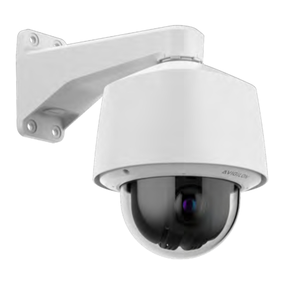
- Page 1 Installation Guide Avigilon H6A PTZ Camera Models: 2.0C-H6A-PTZ-DCM30 2.0C-H6A-PTZ-DPM30 4.0C-H6A-PTZ-DCM30 4.0C-H6A-PTZ-DPM30 2.0C-H6A-PTZ-DC30 2.0C-H6A-PTZ-DP30...
- Page 2 Legal Notices © 2024, Avigilon Corporation. All rights reserved. AVIGILON, the AVIGILON logo, AVIGILON CONTROL CENTER, and ACC are trademarks of Avigilon Corporation. ONVIF is a trademark of Onvif, Inc. Covered by one or more claims of the patents listed at patentlist.hevcadvance.com. Other names or logos mentioned herein may be the trademarks of their respective owners.
- Page 3 Important Safety Information This manual provides installation and operation information and precautions for the use of this device. Incorrect installation could cause an unexpected fault. Before installing this equipment read this manual carefully. Please provide this manual to the owner of the equipment for future reference. WARNING This Warning symbol indicates the presence of dangerous voltage within and outside the product enclosure that may result in a risk of electric shock, serious injury or death to persons if proper...
- Page 4 Do not expose the camera directly to high levels of x-ray, laser, or UV radiation. Direct exposure may cause permanent damage to the image sensor. Do not install near any heat sources such as radiators, heat registers, stoves, or other sources of heat. Do not subject the device cables to excessive stress, heavy loads or pinching.
- Page 5 Regulatory Notices This device complies with part 15 of the FCC Rules. Operation is subject to the following two conditions: (1) this device may not cause harmful interference, and (2) this device must accept any interference received, including interference that may cause undesired operation. Pendant mount models comply with EN 60529 IP66 and IP67 ratings.
- Page 6 For Korea Disposal and Recycling Information When this product has reached the end of its useful life, please dispose of it according to your local environmental laws and guidelines. European Union: This symbol means that according to local laws and regulations your product should be disposed of separately from household waste.
-
Page 7: Table Of Contents
Table of Contents Overview In-Ceiling Back Box (Top View) Pendant Back Box (Top View) Dome Drive Back Box (Bottom View) Camera Lower Dome Pendant Wall Mount NPT Mount View In-Ceiling Mount Installation Required Tools and Materials Camera Package Contents Installation Steps Installing the In-Ceiling Back Box Installing the Dome Drive into the Back Box (In-Ceiling) Installing the Dome Cover (In-Ceiling) - Page 8 Troubleshooting Network Connections and LED Behavior Resetting to Factory Default Settings Cleaning Dome Bubble Body For More Information Limited Warranty and Technical Support...
-
Page 9: Overview
Overview In-Ceiling Back Box (Top View) 1. Grommets Provide weatherproofing and protection around the cables that pass through the camera housing. 2. Spring Clips Spring loaded clips that secure the camera to the ceiling tile. Overview... -
Page 10: Pendant Back Box (Top View)
Pendant Back Box (Top View) 1. NPT Thread 1 1/2-inch NPT thread included in the back box for attaching to camera mounts. 2. Grommet Provides weatherproofing and protection around the cables that pass through the camera housing. Pendant Back Box (Top View) -
Page 11: Dome Drive
Dome Drive 1. Tamper Resistant Screws Captive screws to fix the dome drive to the back box. 2. microSD Card Slots Accepts up to two microSD cards for onboard storage. Install microSD cards so the metal contacts are facing (Optional) Configuring microSD Card Storage on page inward. -
Page 12: Back Box (Bottom View)
Back Box (Bottom View) 1. Ethernet port Connects the camera to the IP network and supplies power to the camera through the network using Power over Ethernet 802.3bt or 802.3at for indoor models only and ambient temperatures above -10°C. 2. Alarm, Relay, and Audio In/Out An 16-pin connector with four alarms, two relay, and audio in and out. -
Page 13: Camera Lower Dome
Camera Lower Dome 1. Trim ring Protective ring attached to the lower part of the camera's dome housing. 2. Tamper resistant screws Star-shaped captive screws to fix the dome cover to the base. 3. Dome cover Vandal resistant dome cover. Camera Lower Dome... -
Page 14: Pendant Wall Mount
Pendant Wall Mount 1. 1-1/2” NPS thread mount Female NPS thread mount for pendant camera installations. 2. Pendant wall mount screws Screws (user supplied) for securing the pendant wall mount to the mounting bracket. 3. NPT pipe entry hole A 3/4” NPT threaded hole for NPT pipe conduits. NOTE The pendant wall mount is sold separately. -
Page 15: Npt Mount View
NPT Mount View 1. NPT Pipe NPT pipe for mounting camera. 2. 1-1/2: NPT female to NPT-female adapter An adapter for attaching the pendant back box to an NPT pipe. 3. Lock nut Locking nut for securing the pendant back box on the NPT-female to NPT-female adapter. 4. -
Page 16: In-Ceiling Mount Installation
In-Ceiling Mount Installation Required Tools and Materials The following tools are required to complete the installation but are not included in the package: Appropriate tool for cutting the entry hole in the mounting surface Power drill that can be used as a screwdriver Cate 5e (or higher) ethernet cable RJ-45 connector to terminate the ethernet cable if not already terminated RJ-45 Crimp Tool... -
Page 17: Installing The In-Ceiling Back Box
Installing the In-Ceiling Back Box NOTE The maximum supported ceiling thickness is 38.1 mm (1.5"). 1. Use the in-ceiling mounting template to cut an entry hole for the camera into the ceiling. 2. Pull the cables through the mounting surface. There will be three cables total. One Ethernet Cable with RJ45, a pair of power cables with stripped leads for 24 VAC/DC applications, and a 1~16 multi-wire cable bundle. - Page 18 3. Remove a grommet in the back box to feed the cables through. Choose the top or side grommet option. Optional: Grommet(s) can be replaced with 3/4" conduit fittings and pipe (not supplied) for routing of the cables. 4. First, feed the RJ45 cable through the grommet with the supplied insertion tool. The RJ45 cable has to be the first cable fed through the grommet.
- Page 19 5. Terminate the pair of power cables to the supplied, two-pin, removable header with screw down terminals. 6. Terminate the 1~16 multi-wire cable bundle to the supplied 16-pin removable header with push-in terminals. For more information, see Connecting to Power and External Devices on page 7.
- Page 20 8. Push the back box (with grommet and cables attached), into the ceiling hole. Secure the back box in the ceiling using the two spring clips. Tighten the two screws using the supplied power bit and a power driver or drill.
-
Page 21: Installing The Dome Drive Into The Back Box (In-Ceiling)
Installing the Dome Drive into the Back Box (In-Ceiling) After you install the back box, mount the dome drive to the back box. (Optional) 1. Insert one or two SD cards in the slots in the dome drive. For more information, see the Configuring microSD Card Storage on page 2. -
Page 22: Installing The Dome Cover (In-Ceiling)
Installing the Dome Cover (In-Ceiling) NOTE Before installing the dome cover, we recommend that you first connect to the camera. For more information, see: Connecting to the Camera on page 35 NOTE Be careful not to scratch the dome bubble. Do not remove the protective film until after installation. 1. -
Page 23: Pendant Mount Installation
60lbs (30kg). (optional) Package Contents Ensure the dome camera package contains the following: Avigilon H6A PTZ Camera Pendant Back box Lower Dome (includes trim ring and bubble) Dome Drive... -
Page 24: Installation Steps
Pendant Wall Mount (WLMT-1031 or WLMT-1021) Wall Mount mounting template For Installation to a Pipe, the following user supplied items are required: 1-1/2" NPT-female to 1-1/2" NPT-female adapter 1-1/2" Conduit or Pipe IMPORTANT These items are not supplied by Avigilon and should be sourced separately. Installation Steps Complete the following sections to install the device. -
Page 25: (Optional) Mounting The Dome Camera To The Pendant Wall Mount
(Optional) Mounting the Dome Camera to the Pendant Wall Mount If the dome camera will be using the pendant wall mount, you will need to attach it to the pendant back box. 1. Determine where the cables will enter the pendant wall mount. If the cables will be pulled from inside the mounting surface, use the cable entry hole at the rear of the pendant wall mount. - Page 26 5. Remove a grommet in the back box to feed the cables through. 6. Screw the locknut into the back box. Tighten the locknut using tongue and groove pliers. 7. Apply the supplied Teflon tape to the threads in the back box. 8.
- Page 27 c. Feed an already terminated Ethernet cable through the grommet using the supplied insertion tool. NOTE If the insertion tool is not used, then the Ethernet cable needs to be terminated with an RJ45 connector (not supplied) after being passed through the grommet. 9.
- Page 28 11. Once all of the cables are terminated (after being fed through the grommet), feed that entire bundle through the back box and seat the grommet. 12. Screw the pendant back box into the wall arm and tighten. (Optional) Mounting the Dome Camera to the Pendant Wall Mount...
-
Page 29: Installing The Dome Drive To The Back Box (Pendant)
13. Connect the cables to the power supply board's (PCB's) printed circuit board assembly (PCBA) inside the bottom of the back box. a. Connect the cable for network/PoE or network. The connector on the camera is a RJ45. b. Connect the cable for auxiliary power. c. -
Page 30: Installing The Dome Cover (Pendant)
Installing the Dome Cover (Pendant) NOTE Before installing the dome cover, we recommend that you first connect to the camera. For more information, see: Connecting to the Camera on page 35 Installing the Dome Cover (Pendant) -
Page 31: Mounting The Dome Camera To A Pipe
1. Attach the lanyard to secure the lower dome. There is a post on the back box that the lanyard is bolted to. 2. Hold the lower dome in place and fasten the two screws to secure it. The lower dome has captive screws, so they will hang from the trim ring, but they will not fall off. - Page 32 1. Pull the required cables through the NPT conduit pipe. 2. Apply thread seal tape to the pipe and screw on the 1-1/2" NPT female to NPT female pipe adapter. 3. Screw the lock nut onto the pendant back box. 4.
-
Page 33: Cable Connections
Cable Connections Connecting to Power and External Devices The camera may be powered with PoE and/or through the auxiliary power cable using either a 24 VDC or 24 VAC (RMS) auxiliary power source that supports up to 71W or 85VA. Seamless Failover Redundant power with seamless failover is available on the PTZ camera. - Page 34 Description Plastic Cover Pin-Out RELAY COM RELAY NO 12V OUT RETURN (GND) 12V OUT DIGITAL OUT RETURN (GND) DIGITAL OUT AUDIO IN AUDIO IN RETURN (GND) AUDIO OUT AUDIO OUT RETURN (GND) ALARM 3 RETURN (GND) ALARM 3 ALARM 2 RETURN (GND) ALARM 2 ALARM 1 RETURN (GND) ALARM 1...
-
Page 35: Connecting To The Camera
Connecting to the Camera Initializing a Camera Username and Password IMPORTANT You must create a user with administrator privileges before the camera is operational. The first user can be created using any of the following methods: Camera's Web Interface: enter the camera's IP address in a web browser to access the web interface. If the camera is in the factory default state you will be redirected to the Add a new user page to create the first user. -
Page 36: Accessing The Live Video Stream
Accessing the Live Video Stream Live video stream can be viewed using one of the following methods: Web browser interface: http:// < camera IP address>/ . Network Video Management software application (for example, the Avigilon Unity Video software). Accessing the Live Video Stream... -
Page 37: (Optional) Configuring Microsd Card Storage
(Optional) Configuring microSD Card Storage To use the camera's SD card storage feature, you must insert a microSD card into the card slot. It is recommended that the microSD card have a write speed of class V10 or better. If the microSD card does not meet the recommended write speed, the recording performance may suffer and result in the loss of frames or footage. -
Page 38: Setting The Home Preset Position
Setting the Home Preset Position The PTZ camera supports self-learning video analytics from the home preset position. The home preset position is typically the field of view the PTZ camera returns to after being used for investigations. Before you can configure the camera's home position, you must connect the camera to a site in the ACC™ Client software. -
Page 39: Connection Status Led Indicator
Connection Status LED Indicator Once connected to the network, the green Connection Status LED indicator will display the progress in connecting to the Network Video Management software. The following table describes what the LED indicator shows: Connection State Connection Status Description LED Indicator Obtaining... - Page 40 LED Behavior Suggested Solution described above revert button. Resetting through the camera's web interface will not produce the desired result. Troubleshooting Network Connections and LED Behavior...
-
Page 41: Resetting To Factory Default Settings
Resetting to Factory Default Settings If the device no longer functions as expected, you can choose to reset the device to its factory default settings. Use the firmware revert button to reset the device. The firmware revert button is shown in the following diagram: 1. -
Page 42: Cleaning
Cleaning Dome Bubble If the video image becomes blurry or smudged in areas, it may be because the dome bubble requires cleaning. To clean the dome bubble: Use hand soap or a non-abrasive detergent to wash off dirt or fingerprints. Use a microfiber cloth or non-abrasive fabric to dry the dome bubble. -
Page 43: For More Information
For More Information Additional information about setting up and using the device is available in the following guides: Avigilon Control Center Client User Guide Avigilon IP Camera Web Interface User Guide Camera Configuration Tool User Guide Designing a Site with Avigilon Video Analytics These guides are available on help.avigilon.com and on the Avigilon website: avigilon.com/support. -
Page 44: Limited Warranty And Technical Support
Limited Warranty and Technical Support Avigilon warranty terms for this product are provided at avigilon.com/warranty. Warranty service and technical support can be obtained by contacting Avigilon Technical Support: avigilon.com/contact. Limited Warranty and Technical Support...
Need help?
Do you have a question about the Avigilon H6A and is the answer not in the manual?
Questions and answers