
Subscribe to Our Youtube Channel
Related Manuals for Motorola solutions PELCO Spectra SPDE8-2X30-ID1


Summary of Contents for Motorola solutions PELCO Spectra SPDE8-2X30-ID1
- Page 1 Spectra Enhanced 8 PTZ Camera Installation Manual Camera Models: SPDE8-2X30-ID1 SPDE8-2X30-PD1 SPDE8-4X30-ID1 SPDE8-4X30-PD1 SPDE8-2X30-ID0 SPDE8-2X30-PD0 Document number: C6763M Publication date: 12/2023...
-
Page 2: Legal Notices
Spectra Enhanced 8 PTZ Camera Cameras Installation Manual Legal Notices © 2023, Pelco Corporation. All rights reserved. P ELCO, the PELCO logo, PELCO are trademarks of Pelco Corporation. ONVIF is a trademark of Onvif, Inc. Covered by one or more claims of the patents listed at patentlist.hevcadvance.com. O ther names or logos mentioned herein may be the trademarks of their respective owners. The absence of the symbols ™ and ® in proximity to each trademark in this document or at all is not a disclaimer of ownership of the related trademark. Pelco Corporation protects its innovations with patents issued in the United States of America and other jurisdictions worldwide (see www.pelco.com). Unless stated explicitly and in writing, no license is granted with respect to any copyright, industrial design, trademark, patent or other intellectual property rights of Pelco Corporation or its licensors. C6763M | 12/2023... -
Page 3: Disclaimer
Spectra Enhanced 8 PTZ Camera Cameras Installation Manual Disclaimer This document has been compiled and published using product descriptions and specifications available at the time of publication. The contents of this document and the specifications of the products discussed herein are subject to change without notice. Pelco Corporation reserves the right to make any such changes without notice. Neither Pelco Corporation nor any of its affiliated companies: (1) guarantees the completeness or accuracy of the information contained in this document; or (2) is responsible for your use of, or reliance on, the information. Pelco Corporation shall not be responsible for any losses or damages (including consequential damages) caused by reliance on the information presented herein. Pelco Corporation www.pelco.com C6763M Revision: 1 - EN 20231220 C6763M | 12/2023... -
Page 4: Table Of Contents
Spectra Enhanced 8 PTZ Camera Cameras Installation Manual Table of Contents Legal Notices Disclaimer Important Safety Information Regulatory Notices For Korea Disposal and Recycling Information Overview In-Ceiling Back Box (Top View) Pendant Back Box (Top View) Dome Drive Back Box (Bottom View) Camera Lower Dome Pendant Wall Mount NPT Mount View In-Ceiling Mount Installation Required Tools and Materials Camera Package Contents Installation Steps Installing the In-Ceiling Back Box Installing the Dome Drive into the Back Box (In-Ceiling) Installing the Dome Cover (In-Ceiling) Pendant Mount Installation Required Tools and Materials Package Contents Installation Steps (Optional) Mounting the Dome Camera to the Pendant Wall Mount Installing the Dome Drive to the Back Box (Pendant) Installing the Dome Cover (Pendant) Mounting the Dome Camera to a Pipe Cable Connections Connecting to Power and External Devices Seamless Failover External Devices Connection Connecting to the Camera... - Page 5 Spectra Enhanced 8 PTZ Camera Cameras Installation Manual Initializing a Camera Username and Password Assigning an IP Address Setting the IP Address Using the ARP/Ping Method Accessing the Live Video Stream (Optional) Configuring microSD Card Storage Configuring the Camera Focusing the Camera Connection Status LED Indicator Troubleshooting Network Connections and LED Behavior Resetting to Factory Default Settings Cleaning Dome Bubble Body For More Information Limited Warranty and Technical Support Pelco Troubleshooting Contact Information C6763M | 12/2023...
-
Page 6: Important Safety Information
Spectra Enhanced 8 PTZ Camera Cameras Installation Manual Important Safety Information This manual provides installation and operation information and precautions for the use of this device. Incorrect installation could cause an unexpected fault. Before installing this equipment read this manual carefully. Please provide this manual to the owner of the equipment for future reference. WARNING This Warning symbol indicates the presence of dangerous voltage within and outside the product enclosure that may result in a risk of electric shock, serious injury or death to persons if proper precautions are not followed. CAUTION This Caution symbol alerts the user to the presence of hazards that may cause minor or moderate injury to persons, damage to property or damage to the product itself if proper precautions are not followed. WARNING Failure to observe the following instructions may result in severe injury or death. Installation must be performed by qualified personnel only, and must conform to all local codes. ESD to the camera when it is operating could cause a temporary loss of video. When servicing the camera, follow the appropriate ESD mitigation procedures. The operator should remove any static by grounding themselves before servicing the camera. This product is intended to be supplied by a UL Listed Power Unit marked “Class 2” or “LPS” or “Limited Power Source” with output rated: In-Ceiling Mount: 24 VAC ± 10%, or 24 VDC ± 10%, or 25.5 W PoE+ IEEE 802.3 at Type 2, Class 4 compliant. Pendant Mount: 24 VAC ± 10%, or 24 VDC ± 10%, or IEEE 802.3at Type 2, Class 4 compliant, or IEEE802.3bt Type 3, Class 6 compliant, or IEE802.3bt Type 4, Class 8 compliant* (*Using anything less than a Type 4, Class 8 PSE will result in reduced environmental and pan/tilt speed specifications.). ... - Page 7 Spectra Enhanced 8 PTZ Camera Cameras Installation Manual CAUTION Failure to observe the following instructions may r esult in injury to persons or damage to the device. Do not expose the camera directly to high levels of x-ray, laser, or UV radiation. Direct exposure may cause permanent damage to the image sensor. Do not install near any heat sources such as radiators, heat registers, stoves, or other sources of heat. Do not subject the device cables to excessive stress, heavy loads or pinching. Do not open or disassemble the device. There are no user serviceable parts. Refer all device servicing to qualified personnel. Servicing may be required when the device has been damaged (such as from a liquid spill or fallen objects), has been exposed to rain or moisture, does not operate normally, or has been dropped. Do not use strong or abrasive detergents when cleaning the device body. Use only accessories recommended by Pelco. C6763M | 12/2023...
-
Page 8: Regulatory Notices
Spectra Enhanced 8 PTZ Camera Cameras Installation Manual Regulatory Notices This device complies with part 15 of the FCC Rules. Operation is subject to the following two conditions: (1) this device may not cause harmful interference, and (2) this device must accept any interference received, including interference that may cause undesired operation. Pendant mount models comply with EN 60529 IP66 and IP67 ratings. This Class A digital apparatus complies with Canadian ICES-003 (A)/NMB-3(A). This equipment has been tested and found to comply with the limits for a Class A digital device, pursuant to part 15 of the FCC Rules. These limits are designed to provide reasonable protection against harmful interference when the equipment is operated in a commercial environment. This equipment generates, uses, and can radiate radio frequency energy and, if not installed and used in accordance with the instruction manual, may cause harmful interference to radio communications. Operation of this equipment in a residential area is likely to cause harmful interference in which case the user will be required to correct the interference at his own expense. Changes or modifications made to this equipment not expressly approved by Pelco Corporation or parties authorized by Pelco Corporation could void the user’s authority to operate this equipment. To meet the requirements of the EN 50121-4 Railway Applications Standard, use an external power supply or POE injector that is also compliant with EN 50121-4. Please contact Pelco for assistance regarding supporting equipment. To meet the requirements of the EN 50130-4 Alarm Systems Applications standard, use an external uninterruptible power supply (UPS). This equipment contains a coin cell battery. R isk of fire, explosion, and burns. Do not disassemble, crush, heat above 100°C (212°F), or incinerate. The use of EMC compliant support and auxiliary equipment with this device is required in order to fully comply with the EMC regulatory standards. C6763M | 12/2023... -
Page 9: For Korea
Spectra Enhanced 8 PTZ Camera Cameras Installation Manual For Korea Disposal and Recycling Information When this product has reached the end of its useful life, please dispose of it according to your local environmental laws and guidelines. European Union: This symbol means that according to local laws and regulations your product should be disposed of separately from household waste. When this product reaches its end of life, take it to a collection point designated by local authorities. Some collection points accept products for free. The separate collection and recycling of your product at the time of disposal will help conserve natural resources and ensure that it is recycled in a manner that protects human health and the environment. C6763M | 12/2023... -
Page 10: Overview
Spectra Enhanced 8 PTZ Camera Cameras Installation Manual Overview In-Ceiling Back Box (Top View) 1. Grommets Provide weatherproofing and protection around the cables that pass through the camera housing. 2. Spring Clips Spring loaded clips that secure the camera to the ceiling tile. C6763M | 12/2023... -
Page 11: Pendant Back Box (Top View)
Spectra Enhanced 8 PTZ Camera Cameras Installation Manual Pendant Back Box (Top View) 1. NPT Thread 1 1/2-inch NPT thread included in the back box for attaching to camera mounts. 2. Grommet Provides weatherproofing and protection around the cables that pass through the camera housing. C6763M | 12/2023... -
Page 12: Dome Drive
Spectra Enhanced 8 PTZ Camera Cameras Installation Manual Dome Drive 1. Tamper Resistant Screws Captive screws to fix the dome drive to the back box. 2. microSD Card Slots Accepts up to two microSD cards for onboard storage. Install microSD cards so the metal contacts are facing inward. For more information, see (Optional) Configuring microSD Card Storage on page 40. 3. Link LED Indicator Amber LED indicates if there is an active connection in the Ethernet port, and that the device is receiving power. 4. Firmware Revert Button Use the firmware revert button to reset the device. 5. Connection Status LED Indicator Green LED provides information about device operation. For more information, see Connection Status LED Indicator on page 42. 6. Lens The camera lens is housed behind a protective window. NOTE The camera LEDs will flash and provide status information when the camera is establishing a network connection. Once the camera starrts streaming video, the LEDs will automatically turn off. C6763M | 12/2023... -
Page 13: Back Box (Bottom View)
Spectra Enhanced 8 PTZ Camera Cameras Installation Manual Back Box (Bottom View) 1. Ethernet port Connects the camera to the IP network and supplies power to the camera through the network using Power over Ethernet 802.3bt or 802.3at for indoor models only and ambient temperatures above - 10°C. 2. Alarm, Relay, and Audio In/Out An 16-pin connector with four alarms, two relay, and audio in and out. Use a 24 ~ 30AWG multi conductor cable. For more information, see Connecting to Power and External Devices on page 36. 3. Power Terminal The port is used to connect with a 24 VAC power supply. Use 16 to 20 AWG gage wire. NOTE There is no polarity for the power connection. C6763M | 12/2023... -
Page 14: Camera Lower Dome
Spectra Enhanced 8 PTZ Camera Cameras Installation Manual Camera Lower Dome 1. Trim ring Protective ring attached to the lower part of the camera's dome housing. 2. Tamper resistant screws Star-shaped captive screws to fix the dome cover to the base. 3. Dome cover Vandal resistant dome cover. C6763M | 12/2023... -
Page 15: Pendant Wall Mount
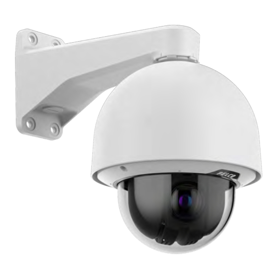
Spectra Enhanced 8 PTZ Camera Cameras Installation Manual Pendant Wall Mount 1. 1-1/2” NPS thread mount Female NPS thread mount for pendant camera installations. 2. Pendant wall mount screws Screws (user supplied) for securing the pendant wall mount to the mounting bracket. 3. NPT pipe entry hole A 3/4” NPT threaded hole for NPT pipe conduits. NOTE The pendant wall mount is sold separately. C6763M | 12/2023... -
Page 16: Npt Mount View
Spectra Enhanced 8 PTZ Camera Cameras Installation Manual NPT Mount View 1. NPT Pipe NPT pipe for mounting camera. 2. 1-1/2: NPT female to NPT-female adapter An adapter for attaching the pendant back box to an NPT pipe. 3. Lock nut Locking nut for securing the pendant back box on the NPT-female to NPT-female adapter. 4. Pendant mount camera Pendant mount camera. NOTE The NPT pipe and the 1-1/2" NPT-female to 1-1/2" NPT-female adapter is not supplied or sold by Pelco and should be sourced separately. C6763M | 12/2023... -
Page 17: In-Ceiling Mount Installation
Spectra Enhanced 8 PTZ Camera Cameras Installation Manual In-Ceiling Mount Installation Required Tools and Materials The following tools are required to complete the installation but are not included in the package: Appropriate tool for cutting the entry hole in the mounting surface Power drill that can be used as a screwdriver Cate 5e (or higher) ethernet cable RJ-45 connector to terminate the ethernet cable if not already terminated RJ-45 Crimp Tool Mini or precision flat head screw diver (optional) 24-30 AWG, up to 16 multi conductor cable for alarms, relays, and/or audio (optional) 16-20 AWG, 2 conductor cable for 2 4V auxiliary power (optional) One or two Micro SD card capable of a minimum write speed of 10 MB/sec is recommended for recording HD video (optional) 3/4" Conduit fittings and pipe (optional) Camera Package Contents Ensure the dome camera package contains the following: Spectra Enhanced 8 PTZ Camera In-Ceiling Back box ... -
Page 18: Installing The In-Ceiling Back Box
Spectra Enhanced 8 PTZ Camera Cameras Installation Manual Installing the In-Ceiling Back Box NOTE The maximum supported ceiling thickness is 38.1 mm (1.5"). 1. Use the in-ceiling mounting template to cut an entry hole for the camera into the ceiling. 2. Pull the cables through the mounting surface. T here will be three cables total. One Ethernet Cable with RJ45, a pair of power cables with stripped leads for 24 VAC/DC applications, and a 1~16 multi- wire cable bundle. C6763M | 12/2023... - Page 19 Spectra Enhanced 8 PTZ Camera Cameras Installation Manual 3. Remove a grommet in the back box to feed the cables through. Choose the top or side grommet option. Optional: Grommet(s) can be replaced with 3/4" conduit fittings and pipe (not supplied) for routing of the cables. 4. First, feed the RJ45 cable through the grommet with the supplied insertion tool. The RJ45 cable has to be the first cable fed through the grommet. a. Two of the grommet holes are the same size and the third is different. Use the third, or smallest, hole for the power cable. b. Use the other two holes for either of the other two cables (e.g. The Ethernet cable can go into either one of the two holes that are the same size.). c. Feed an already terminated Ethernet cable through the grommet using the supplied insertion tool. C6763M | 12/2023...
- Page 20 Spectra Enhanced 8 PTZ Camera Cameras Installation Manual NOTE If the insertion tool is not used, then the Ethernet cable needs to be terminated with an RJ45 connector (not supplied) after being passed through the grommet. 5. Terminate the pair of power cables to the supplied, two-pin, removable header with screw down terminals. 6. Terminate the 1~16 multi-wire cable bundle to the supplied 16-pin removable header with push-in terminals. For more information, see Connecting to Power and External Devices on page 36. 7. Once all of the cables are terminated (after being fed through the grommet), feed that entire bundle through the back box and seat the grommet. C6763M | 12/2023...
- Page 21 Spectra Enhanced 8 PTZ Camera Cameras Installation Manual 8. Push the back box (with grommet and cables attached), into the ceiling hole. Secure the back box in the ceiling using the two spring clips. Tighten the two screws using the supplied power bit and a power driver or drill. 9. Connect the cables to the power supply board's (PCB's) printed circuit board assembly (PCBA) inside the bottom of the back box. a. Connect the cable for network/PoE or network. The connector on the camera is a RJ45. b. Connect the cable for auxiliary power. c. Connect the cable for the auxiliary Inputs/Outputs/Audio. C6763M | 12/2023...
-
Page 22: Installing The Dome Drive Into The Back Box (In-Ceiling)
Spectra Enhanced 8 PTZ Camera Cameras Installation Manual Installing the Dome Drive into the Back Box (In-Ceiling) After you install the back box, mount the dome drive to the back box. 1. Insert one or two SD cards in the slots in the dome drive. For more information, see the (Optional) Configuring microSD Card Storage on page 40. 2. Lift the dome drive into the back box. 3. Snap the dome drive into the back box and secure it by fastening the three screws. C6763M | 12/2023... -
Page 23: Installing The Dome Cover (In-Ceiling)
Spectra Enhanced 8 PTZ Camera Cameras Installation Manual Installing the Dome Cover (In-Ceiling) NOTE Before installing the dome cover, we recommend that you first connect to the camera. For more information, see: Connecting to the Camera on page 38 NOTE Be careful not to scratch the dome bubble. Do not remove the protective film until after installation. C6763M | 12/2023... - Page 24 Spectra Enhanced 8 PTZ Camera Cameras Installation Manual 1. Attach the lanyard to secure the lower dome. There is a post on the back box that the lanyard is bolted to. 2. Hold the lower dome in place and fasten the two screws to secure it. The lower dome has captive screws, so they will hang from the trim ring, but they will not fall off. 3. Remove the protective cover on the outside of the dome bubble. C6763M | 12/2023...
-
Page 25: Pendant Mount Installation
Spectra Enhanced 8 PTZ Camera Cameras Installation Manual Pendant Mount Installation Required Tools and Materials The following tools and materials are required to complete the installation but are not included in the package: Appropriate tool for cutting the entry hole in the mounting surface Power drill that can be used as a screwdriver Tongue and groove pliers Cate 5e (or higher) ethernet cable RJ-45 connector to terminate the ethernet cable if not already terminated RJ-45 Crimp Tool Mini or precision flat head screw diver (optional) 24-30 AWG, up to 16 multi conductor cable for alarms, relays, and/or audio (optional) 16-20 AWG, 2 conductor cable for 24V auxiliary power (optional) One or two Micro SD card capable of a minimum write speed of 10 MB/sec is recommended for recording HD video (optional) 1-1/2" NPT Female to 1-1/2"NPT Female adapter and 1-1/2" conduit/pipe (optional) 3/4" NPT Conduit fitting and pipe (optional) Four 5/16" to 3/8" (M8 to M10) diameter fasteners appropriate for the wall mounting substrate. The type of screw, material, and length is dependent on the substrate and the environment and should be selected to support a minimum of 60lbs (30kg). (optional) Package Contents Ensure the dome camera package contains the following:... -
Page 26: Installation Steps
Spectra Enhanced 8 PTZ Camera Cameras Installation Manual Lock nut Teflon tape Pendant Quick Start Guide For Installation to the Pendant Wall Mount, the following additional items are required (purchased separately): Pendant Wall Mount (WLMT-1031 or WLMT-1021) Wall Mount mounting template For Installation to a Pipe, the following user supplied items are required: 1-1/2" NPT-female to 1-1/2" NPT-female adapter 1-1/2" Conduit or Pipe IMPORTANT These items are not supplied by Pelco and should be sourced separately. Installation Steps C6763M | 12/2023... -
Page 27: (Optional) Mounting The Dome Camera To The Pendant Wall Mount
Spectra Enhanced 8 PTZ Camera Cameras Installation Manual (Optional) Mounting the Dome Camera to the Pendant Wall Mount If the dome camera will be using the pendant wall mount, you will need to attach it to the pendant back box. 1. Determine where the cables will enter the pendant wall mount. If the cables will be pulled from inside the mounting surface, use the cable entry hole at the rear of the pendant wall mount. If the cables will be coming out of an external conduit pipe, use the 3/4” NPT pipe entry hole on the bottom of the pendant wall mount. 2. Use the provided mounting template to drill four mounting holes into the mounting surface. If you are using the rear cable entry hole, also drill the cable entry hole into the mounting surface. 3. Place the pendant wall mount on the mounting surface and screw it in using the user supplied screws. Pull cables through the wall mount if using rear cable entry. 4. If you are using the pipe entry hole, pull the cables through the pipe conduit then the wall mount. Next, apply thread seal tape to the pipe conduit and screw it into the pipe entry hole. C6763M | 12/2023... - Page 28 Spectra Enhanced 8 PTZ Camera Cameras Installation Manual 5. Remove a grommet in the back box to feed the cables through. 6. Screw the locknut into the back box. Tighten the locknut using tongue and groove pliers. 7. Apply the supplied Teflon tape to the threads in the back box. C6763M | 12/2023...
- Page 29 Spectra Enhanced 8 PTZ Camera Cameras Installation Manual 8. First, feed the RJ45 cable through the grommet with the supplied insertion tool. The RJ45 cable has to be the first cable fed through the grommet. a. Two of the grommet holes are the same size and the third is different. Use the third, or smallest, hole for the power cable. b. Use the other two holes for either of the other two cables (e.g. The Ethernet cable can go into either one of the two holes that are the same size.). c. Feed an already terminated Ethernet cable through the grommet using the supplied insertion tool. C6763M | 12/2023...
- Page 30 Spectra Enhanced 8 PTZ Camera Cameras Installation Manual NOTE If the insertion tool is not used, then the Ethernet cable needs to be terminated with an RJ45 connector (not supplied) after being passed through the grommet. 9. Terminate the pair of power cables to the supplied, two-pin, removable header with screw down terminals. 10. Terminate the 1~16 multi-wire cable bundle to the supplied 16-pin removable header with push-in terminals. For more information, see Connecting to Power and External Devices on page 36. 11. Once all of the cables are terminated (after being fed through the grommet), feed that entire bundle through the back box and seat the grommet. C6763M | 12/2023...
-
Page 31: Installing The Dome Drive To The Back Box (Pendant)
Spectra Enhanced 8 PTZ Camera Cameras Installation Manual 12. Screw the pendant back box into the wall arm and tighten. 13. Connect the cables to the power supply board's (PCB's) printed circuit board assembly (PCBA) inside the bottom of the back box. a. Connect the cable for network/PoE or network. The connector on the camera is a RJ45. b. Connect the cable for auxiliary power. c. Connect the cable for the auxiliary Inputs/Outputs/Audio. Installing the Dome Drive to the Back Box (Pendant) After you install the back box, mount the dome drive to the back box. (Optional) 1. Insert one or two SD cards in the slots in the dome drive. For more information, see the Configuring microSD Card Storage on page 40. C6763M | 12/2023... - Page 32 Spectra Enhanced 8 PTZ Camera Cameras Installation Manual 2. Lift the dome drive into the back box. Snap the dome drive into the back box and secure it by fastening the three screws. C6763M | 12/2023...
-
Page 33: Installing The Dome Cover (Pendant)
Spectra Enhanced 8 PTZ Camera Cameras Installation Manual Installing the Dome Cover (Pendant) NOTE Before installing the dome cover, we recommend that you first connect to the camera. For more information, see: Connecting to the Camera on page 38 1. Attach the lanyard to secure the lower dome. There is a post on the back box that the lanyard is bolted to. 2. Hold the lower dome in place and fasten the two screws to secure it. The lower dome has captive screws, so they will hang from the trim ring, but they will not fall off. C6763M | 12/2023... -
Page 34: Mounting The Dome Camera To A Pipe
Spectra Enhanced 8 PTZ Camera Cameras Installation Manual 3. Remove the protective cover on the outside of the dome bubble. Mounting the Dome Camera to a Pipe NOTE This procedure requires a 1-1/2" NPT-female to 1-12" NPT-female pipe adapter. It is recommended that the NPT adapter be mounted to a 1-1/2" conduit pipe. 1. Pull the required cables through the NPT conduit pipe. 2. Apply thread seal tape to the pipe and screw on the 1-1/2" NPT female to NPT female pipe adapter. 3. Screw the lock nut onto the pendant back box. 4. Apply thread seal tape to the NPT adapter and screw it into the pipe adapter. Make sure the parts are assembled in this order from NPT conduit pipe to pendant b ack box: a. NPT conduit pipe b. 1-1/2" NPT female to female pipe adapter c. Lock nut d. Pendant back box 5. Refer to steps 5-13 in this section for more information: (Optional) Mounting the Dome Camera to the Pendant Wall Mount on page 27. ... - Page 35 Spectra Enhanced 8 PTZ Camera Cameras Installation Manual 6. Verify all connections on the Spectra Enhanced 8 PTZ Camera with pipe mount are assembled correctly. C6763M | 12/2023...
-
Page 36: Cable Connections
Spectra Enhanced 8 PTZ Camera Cameras Installation Manual Cable Connections Connecting to Power and External Devices The camera may be powered with PoE and/or through the auxiliary power cable using either a 24 VDC or 24 VAC (RMS) auxiliary power source that supports up to 71W or 85VA. Seamless Failover Redundant power with seamless failover is available on the PTZ camera. Seamless failover allows the camera to transition between PoE and auxiliary power sources without any interruption of camera operation. This is mainly useful if you want redundant power sources so that power will be available if one power source goes down. The axillary power source takes priority in providing power. NOTE Seamless failover is only guaranteed when IEE802.3bt power for outdoor cameras or IEE803.at power for indoor cameras is available on the PoE port. Auxiliary (Aux) power is always assumed to be sufficient meaning that there is enough power available for all possible camera functions. To power the camera, use 2-pin plug in connector (supplied with the camera), connect the two power wires to the connector and plug it into camera. The connection can be made with either polarity. 18AWG or heavier wires recommended for most cable runs between the 24VAC/VDC power source and the camera. If a longer cable run is required, a wire gauge table should be consulted to ensure that the voltage at the camera does not drop outside of the specified range when the camera is operating at the maximum rated power draw. Power supplies and external devices are connected to the camera through the power and I/O wires. WARNING This product is intended to be powered by a UL Listed Power Unit marked "Class 2" or "LPS" or "Limited Power Source" with output rated 24VAC±10%, 85 VA min; 24VDC±10%, 71 W min. or a 90W PoE BT (outdoor cameras) or 30W PoE AT (indoor cameras) mid-span injector. External Devices Connection External devices are connected to the camera through the supplied I/O 16-pin plug in connector. The pinout for the I/O connector is shown in the following diagram. C6763M | 12/2023... - Page 37 Spectra Enhanced 8 PTZ Camera Cameras Installation Manual Description Plastic Cover Pin-Out RELAY COM RELAY NO 12V OUT RETURN (GND) 12V OUT DIGITAL OUT RETURN (GND) DIGITAL OUT AUDIO IN AUDIO IN RETURN (GND) AUDIO OUT AUDIO OUT RETURN (GND) ALARM 3 RETURN (GND) ALARM 3 ALARM 2 RETURN (GND)
-
Page 38: Connecting To The Camera
Spectra Enhanced 8 PTZ Camera Cameras Installation Manual Connecting to the Camera Initializing a Camera Username and Password IMPORTANT You must create a user with administrator privileges before the camera is operational. The new user can be created using the following methods: Camera's web interface. Enter the camera's IP address in a web browser to access the web interface. For more information, see the Pelco Spectra Enhanced 8 PTZ Camera Operations Manual . If the camera is in the factory default state, you will be redirected to the New User page to create an administrator user: 1. Enter a new User Name or keep the default administrator name. 2. Enter a new Password for the user. It is recommended to use a secure and complex password. 3. Confirm the new password. 4. For the first user, Administrator must be selected in the Security Group drop-down menu. 5. Click Apply. After creating the user, you will be asked to login. Camera Configuration Tool: discovered cameras that are identified by will require a first user to be set. Select the Admin Users tab to create the first user. For more information, see the Camera Configuration Tool User Guide . ... -
Page 39: Setting The Ip Address Using The Arp/Ping Method
Spectra Enhanced 8 PTZ Camera Cameras Installation Manual The mobile web interface using the USB WiFi Adapter. For more information, see (Optional) Using the USB Wi-Fi Adapter. Device's web browser interface: http:// <camera IP address>/ . Network Video Management software application. ARP/Ping method. For more information, see Setting the IP Address Using the ARP/Ping Method below. Setting the IP Address Using the ARP/Ping Method NOTE The ARP/Ping Method will not work if the Disable setting static IP address through ARP/Ping method checkbox is selected in the camera's device's web browser interface. For more information, see the PelcoSpectra Enhanced 8 PTZ Camera Operations Manual Complete the following steps to configure the camera to use a specific IP address: 1. Locate and make note of the MAC Address (MAC) listed on the Serial Number Tag for reference. 2. Open a Command Prompt window and enter the following commands: a. arp -s <New Camera IP Address> <Camera MAC Address> For example: arp -s 192.168.1.10 00-18-85-12-45-78 b. ... -
Page 40: (Optional) Configuring Microsd Card Storage
Spectra Enhanced 8 PTZ Camera Cameras Installation Manual (Optional) Configuring microSD Card Storage To use the c amera's SD card storage feature, you must insert a microSD card into the card slot. It is recommended that the microSD card have a write speed of class V10 or better. If the microSD card does not meet the recommended write speed, the recording performance may suffer and result in the loss of frames or footage. 1. Insert a microSD card into the camera. Do not force the microSD card into the camera or you may damage the card and the camera. 2. Access the camera’s web interface to enable the onboard storage feature. For more information, see the Pelco Spectra Enhanced 8 PTZ Camera Operations Manual . Configuring the Camera After the camera is installed, configure it using the instructions in the current version of the Pelco Spectra Enhanced 8 PTZ Camera Operations Manual . C6763M | 12/2023... -
Page 41: Focusing The Camera
Spectra Enhanced 8 PTZ Camera Cameras Installation Manual Focusing the Camera Ensure this procedure is performed after the dome cover is installed so you can accommodate for the focus shift caused by the dome bubble. Ensure you adjust the focus for your Spectra Enhanced 8 PTZ Camera camera. In the camera web browser interface, use the camera’s Image and Display settings to focus the camera. 1. Click Auto Focus to focus the lens. 2. Use the focus near and far buttons to manually adjust the focus. C6763M | 12/2023... -
Page 42: Connection Status Led Indicator
Spectra Enhanced 8 PTZ Camera Cameras Installation Manual Connection Status LED Indicator Once connected to the network, the green Connection Status LED indicator will display the progress in connecting to the Network Video Management software. The following table describes what the LED indicator shows: Connection State Connection Status Description LED Indicator Obtaining One short flash Attempting to obtain an IP address. IP Address every second Discoverable Two short flashes Obtained an IP address but not connected to the every second Network Video Management software. Upgrading Two short flashes Updating the firmware. Firmware and one long flash every second Connected Connected to the Network Video Management software. The default connected setting can be changed to Off using the camera's web user interface. For more information, see the Pelco Spectra Enhanced 8 PTZ Camera Operations Manual . Troubleshooting Network Connections and LED Behavior NOTE For any of the below LED behaviors, ensure that the camera is getting power and is using ... - Page 43 Spectra Enhanced 8 PTZ Camera Cameras Installation Manual LED Behavior Suggested Solution the blinking interface will not produce the desired result. A different LED blinking pattern than Perform a factory reset of the camera using the physical those described above firmware revert button. Resetting through the camera's web interface will not produce the desired result. C6763M | 12/2023...
-
Page 44: Resetting To Factory Default Settings
Spectra Enhanced 8 PTZ Camera Cameras Installation Manual Resetting to Factory Default Settings If the device no longer functions as expected, you can choose to reset the device to its factory default settings. Use the firmware revert button to reset the device. The firmware revert button is shown in the following diagram: 1. Ensure the device is powered on. 2. Using a straightened paperclip or similar tool, gently press and hold the firmware revert button. 3. Release the button after three seconds. CAUTION Do not apply excessive force. Inserting the tool too far may damage the camera. C6763M | 12/2023... -
Page 45: Cleaning
Spectra Enhanced 8 PTZ Camera Cameras Installation Manual Cleaning Dome Bubble If the video image becomes blurry or smudged in areas, it may be because the dome bubble requires cleaning. To clean the dome bubble: Use hand soap or a non-abrasive detergent to wash off dirt or fingerprints. Use a microfiber cloth or non-abrasive fabric to dry the dome bubble. IMPORTANT Failure to use the recommended cleaning materials may result in a damaged or scratched dome bubble. A damaged dome bubble may negatively impact image quality and cause unwanted IR light reflecting into the lens. Body Use a dry or lightly dampened cloth to clean the camera body. Do not use strong or abrasive detergents. C6763M | 12/2023... -
Page 46: For More Information
Spectra Enhanced 8 PTZ Camera Cameras Installation Manual For More Information Additional information about setting up and using the device is available in the following guides: Pelco Spectra Enhanced 8 PTZ Camera Operations Manual available on the Pelco website: www.pelco.com. Camera Configuration Tool User Guide C6763M | 12/2023... -
Page 47: Limited Warranty And Technical Support
Spectra Enhanced 8 PTZ Camera Cameras Installation Manual Limited Warranty and Technical Support Pelco warranty terms for this product are provided at pelco.com/warranty. Warranty service and technical support can be obtained by contacting Pelco Technical Support: pelco.com/contact. C6763M | 12/2023... -
Page 48: Pelco Troubleshooting Contact Information
Spectra Enhanced 8 PTZ Camera Cameras Installation Manual Pelco Troubleshooting Contact Information For further assistance, contact Pelco Product Support at 1-800-289-9100 (USA and Canada) or +1-559- 292-1981 (international). Do not try to repair the unit yourself. Leave maintenance and repairs to qualified technical personnel only. C6763M | 12/2023... - Page 49 Spectra Enhanced 8 PTZ Camera Cameras Installation Manual C6763M | 12/2023...
Need help?
Do you have a question about the PELCO Spectra SPDE8-2X30-ID1 and is the answer not in the manual?
Questions and answers