
Related Manuals for Belden Grass Valley HCO-3901


Summary of Contents for Belden Grass Valley HCO-3901
- Page 1 GUIDE TO INSTALLATION AND OPERATION HCO-3901 3G/HD/SD/ASI Change Over with optional Clean Switch and ALC Guide to Installation and Operation M981-9900-125 2017-08-07 HCO-3901...
- Page 2 Copyright © 2012-2017, Grass Valley Canada. All rights reserved. Belden, Belden Sending All The Right Signals, and the Belden logo are trademarks or registered trademarks of Belden Inc. or its affiliated companies in the United States and other jurisdictions. Grass Valley, Miranda, HCO-3901, iControl, and Densité...
- Page 3 GUIDE TO INSTALLATION AND OPERATION Electromagnetic Compatibility This equipment has been tested for verification of compliance with FCC Part 15, Subpart B requirements for Class A digital devices. NOTE: This equipment has been tested and found to comply with the limits for a Class A digital device, pursuant to part 15 of the FCC Rules.
-
Page 4: Table Of Contents
GUIDE TO INSTALLATION AND OPERATION Table of Contents HCO-3901 3G/HD/SD/ASI Change Over with Clean Switch and ALC........1 Introduction ............................1 Features............................... 1 Block Diagram ............................. 2 Front Card-edge Interface ........................3 Installation ..........................4 Installation in the Densité frame ......................4 Rear Connector Panels ........................ -
Page 5: Hco-3901 3G/Hd/Sd/Asi Change Over With Clean Switch And Alc
1 HCO-3901 3G/HD/SD/ASI Change Over with Clean Switch and ALC 1.1 Introduction The HCO-3901 from Grass Valley, a Belden Brand, is a 3x1 3G/HD/SD/ASI change-over which support 16 channels of embedded audio and metadata. The module can perform a video and audio “Clean and Silent Switch” between sources using the CS option (not available with ASI signals). -
Page 6: Block Diagram
GUIDE TO INSTALLATION AND OPERATION • Alarm reporting to iControl facility monitoring and control system • Compatible with iControl end-to-end A/V fingerprint analyzer for lip sync error detection and measurement (not available with ASI signals) • GPI in and out (IN 1, IN 2, IN 3, auto, bypass) •... -
Page 7: Front Card-Edge Interface
GUIDE TO INSTALLATION AND OPERATION Figure 1-2 Functional block diagram - HCO-3901 (shown with the HCO-3901-3DRP-R-EX rear panel) 1.4 Front Card-edge Interface The front card-edge of the HCO-3901 incorporates two elements: • Status LED (see section 3.2) • Select Button (see section 3.3) An additional connector is present, intended for future use. -
Page 8: Installation
GUIDE TO INSTALLATION AND OPERATION 2 Installation 2.1 Installation in the Densité frame The HCO-3901 and its associated rear connector rear panel must be mounted in a Densité-3 or Densité-3+ series frame, or in a GV Node. • It is not necessary to switch off the frame’s power when installing or removing the card. •... - Page 9 GUIDE TO INSTALLATION AND OPERATION HCO-3901-3DRP-R-EX – Double-width Densité-3 rear with bypass relay and DIN connectors. This rear features extra PGM and PWV outputs. Outputs designated by a black circle are phase-inverted and not suitable for ASI. HCO-3901-3DRP-R – double-width Densité-3 rear with bypass relay and BNC connectors. HCO-3901-3SRP-R –...
- Page 10 GUIDE TO INSTALLATION AND OPERATION The HCO-3901 provides up to eight 3G/HD/SD SDI video outputs (depending on the rear panel in use), labeled PGM (program) and PVW1, PVW2 and PVW3 (preview). The SDI video signals conform to the SMPTE 292M, SMPTE 259M-C and SMPTE 425M standards.
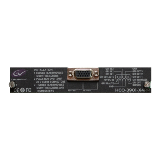
- Page 11 GUIDE TO INSTALLATION AND OPERATION The GPIO interface is implemented on an HD-15 connector. The pinout is as follows: GPI Label Pin # GPI-IN-1 GPI-IN-2 GPI-IN-3 GPI-BYPASS-IN GPI-AUTO-IN GPI-OUT-1 GPI-OUT-2 GPI-OUT-3 GPI-BYPASS-OUT GPI-AUTO-OUT GPI-PWR-IN 8,12,13,14 Note: Users may find it convenient to purchase Grass Valley’s NSH-15M HD15-to-terminal-block adapter, which provides easy access to the GPI-I/O pins.
-
Page 12: Operation
GUIDE TO INSTALLATION AND OPERATION 3 Operation 3.1 Control options The HCO-3901 can be controlled in different ways: • The local control panel and its push-buttons can be used to move through a menu of parameters and to adjust parameter values (see section 3.3). •... -
Page 13: Local Control Using The Densité Frame Control Panel
GUIDE TO INSTALLATION AND OPERATION 3.3 Local control using the Densité frame control panel There are two types of local control panel: Panel type Frame models Appearance Physical Densité-2, Densité-3, Densité-3+FR1, Touch screen Densité 3+FR4, GV Node The local control panel is fastened to the front of the controller card. •... -
Page 14: Remote Control Using Icontrol
GUIDE TO INSTALLATION AND OPERATION 3.4 Remote control using iControl The operation of the HCO-3901 may be controlled using Grass Valley’s iControl system. • This manual describes the control panels associated with the HCO-3901 and their use. • Please consult the iControl User’s Guide for information about setting up and operating iControl. In iControl Navigator or iControl Websites, double-click on the HCO-3901 icon to open the control panel. -
Page 15: The Switch Panel
GUIDE TO INSTALLATION AND OPERATION Icon 3 – Input 1 status • A: Green - Status OK; format shown • B: Red – Error Icon 4 – Input 2 status • A: Green - Status OK • B: Red - Error Icon 5 –... - Page 16 GUIDE TO INSTALLATION AND OPERATION The graphic at the top of the panel identifies the input that is currently selected, and indicates the validity of all 3 inputs by the color of their icons. 1. Manual switch Manually switches the HCO-3901 output between the three possible sources: input 1, input 2 or input 3.
- Page 17 GUIDE TO INSTALLATION AND OPERATION Auto mode operation: • If Input 1 fails with an alarm level of higher priority than input 2, the HCO-3901 will automatically switch over to Input 2 • If the Switch Mode has been set to Switch and Return (see below), the HCO-3901 can automatically switch back to Input 1 if it has a lower alarm priority than input 2.
-
Page 18: The Alarms Panel
GUIDE TO INSTALLATION AND OPERATION Preview Output tab Use this tab to select the source for the three preview outputs. • Auto Selects the Preview output based on the current program output: Program Preview Input 1 Input 2 Input 2 Input 1 Input 3 Input 3... - Page 19 GUIDE TO INSTALLATION AND OPERATION Some alarms are arbitrarily assigned as Level 1 and cannot be changed by the user (e.g. Video Error is always a Level 1 alarm). Their Enable checkbox is ticked, and greyed-out. Other alarms have a pulldown in their control panel that allows the user to set the level.
- Page 20 GUIDE TO INSTALLATION AND OPERATION Video – Format Mismatch The user sets an expected format for each input using the pulldown in the control panel. The HCO-3901 compares this with the actual format detected at the input, and flags an error if they do not match, after a 0.5 second delay.
- Page 21 GUIDE TO INSTALLATION AND OPERATION Video – Black Detect This error detects the presence of a continuous black signal for a period of time; the error is flagged only when the time duration criterion has been satisfied. This error can be Enabled using the checkbox, and the level set to 1, 2 or OFF.
- Page 22 GUIDE TO INSTALLATION AND OPERATION • Set Duration (sec) – sets the time interval over which a freeze must be continuously detected before the error is flagged. The nominal range of durations is 1 to 90 seconds. There is an additional 0.5 seconds intrinsic to the error detection algorithm that will prevent switching when there are nearly-coincident errors at the two inputs.
-
Page 23: The Timing Panel
GUIDE TO INSTALLATION AND OPERATION Use the LED Color pulldown to choose the color that will be displayed by the status LED on the card edge when a Silence CH error is detected. Choices are: • Green, Yellow, Red, Flashing Red Global alarms The parameters found under the Global tab do not have individual control panels. - Page 24 GUIDE TO INSTALLATION AND OPERATION • Example (a) shows the supported input timing window for a user-programmed output timing of +1 line. In order for the HCO-3901 to guarantee no output timing errors, the input signal must be phased to within -1 line of the reference signal and +1 line –...
-
Page 25: The Operation Mode Panel
GUIDE TO INSTALLATION AND OPERATION 3.4.5 The Operation Mode panel Use the radio buttons in the Operation Format box to choose whether this HCO-3901 will operate using 3G/HD/SD, or ASI. Figure 3.21 Operation Mode Panel 3.4.6 The Reference panel The HCO-3901 output signals should always be genlocked to some reference source. -
Page 26: The Audio Embed Panel
GUIDE TO INSTALLATION AND OPERATION Note that when the ALC option is active but clean switch is not active (either the option has not been purchased, or is available but not activated), the reference source is forced to the selected input. The user can select a different reference here, but that selection will only become active when clean switch is activated. - Page 27 GUIDE TO INSTALLATION AND OPERATION Note: The ALC works with PCM audio. If non-PCM audio like Dolby-E or AC-3 is fed to the module, it will be ignored and all the program channels will be bypassed to prevent interference with the other PCM audio channel 3.4.8.1 Config tab Channels per program Pull-downs are available to select the number of channels...
- Page 28 GUIDE TO INSTALLATION AND OPERATION ability to tightly follow the target output loudness. Using this preset, the program content will sound a little more dense, while keeping most of the original program dynamic range. • Factory Standard – The ALC applies moderate dynamic range compression on the audio program content. The overall response time is also moderate, which allows the ALC to follow the target output loudness quite well.
-
Page 29: The Fingerprint Panel
GUIDE TO INSTALLATION AND OPERATION The ALC Fast Mode Response kicks in whenever the input loudness goes over the Fast Mode Threshold and loudness is reduced, in a few milliseconds. The Fast Mode Threshold is given in dB with respect to the target loudness and ranges from 2 to 12 dB, in dB steps. - Page 30 GUIDE TO INSTALLATION AND OPERATION Note: The windows for Inputs 1 and 2 can be adjusted independently. The PGM Output window settings follow those of the selected input, and are shown in the tab but cannot be adjusted there. Zone Select the area of the image within which fingerprint data will be calculated and streamed.
-
Page 31: The Ralm Panel
GUIDE TO INSTALLATION AND OPERATION 3.4.10 The RALM panel The Remote Audio Level Meter (RALM) panel displays audio level meters that can be assigned to audio arriving at both inputs of the HCO-3901. Use the checkboxes in the RALM Remote Control section at the bottom of the panel to select the audio to be displayed on the meters. -
Page 32: The Thumbnail Panel
GUIDE TO INSTALLATION AND OPERATION Upper Zone Limits – select the crossover level between the upper and middle zones of the meter (the range of values shown in the pull-down list depends on the type of meter selected) Lower Zone Limits – select the crossover level between the middle and lower zones of the meter (the range of values shown in the pull-down list depends on the type of meter selected) Color samples –... -
Page 33: The Options Panel
GUIDE TO INSTALLATION AND OPERATION Mode – select between Video mode and Test mode. Use Video mode for normal operation. Format – choose the thumbnail size: • small, medium, large Quality – choose the quality of the displayed image • Poor, Normal, HiQ Refresh Rate –... - Page 34 GUIDE TO INSTALLATION AND OPERATION • Reclocked outputs. 7. If there are no errors on input 1 but a reference mismatch is detected on input 2, the CSO keeps working. The Options panel gives some information about obtaining the Clean Switch option, and provides a data entry box “Enter Key”...
-
Page 35: The Factory Panel
GUIDE TO INSTALLATION AND OPERATION 3.4.13 The Factory panel The HCO-3901 maintains a “Factory Default” alignment in its memory, to which it can be restored at any time. • Click the Load Factory button to restore the card to its Factory default alignment. -
Page 36: The Alarm Config Panel
GUIDE TO INSTALLATION AND OPERATION 3.4.14 The Alarm Config panel This panel allows the alarm reporting of the HCO- 3901 to be configured. The panel opens in a new window when the button is clicked, and can be resized if needed. The panel is organized in columns. - Page 37 GUIDE TO INSTALLATION AND OPERATION Levels associated with these alarms: The pulldown lists may contain some or all of the following options: The alarm makes no contribution (black icon) The alarm is of minor importance (yellow icon) The alarm is of major importance (orange icon) The alarm is of critical importance (red icon) The alarm exists but has no effect (used for text and composite alarms) Shortcut: if you click in one of the Set All boxes beside a section heading, you will open a pulldown that lets...
-
Page 38: The Info Panel
GUIDE TO INSTALLATION AND OPERATION 3.4.15 The Info panel When the HCO-3901 is included in an iControl environment, certain information about the card should be available to the iControl system. The user can enter labels and comments that will make this card easy to identify in a complex setup. This information is entered via the Info control panel. -
Page 39: User Presets
GUIDE TO INSTALLATION AND OPERATION • Remote System Administration – opens the Joining Locators data box, which lists remote lookup services to which this HCO-3901 is registered. Add: Force the iControl service for this HCO-3901 to register itself on a user-specified Jini lookup service, using the following syntax: jini://<ip_address>... -
Page 40: Profiles
GUIDE TO INSTALLATION AND OPERATION 3.4.17 Profiles This section provides the option to save and recover the entire card configuration (including user presets if desired) on an external disk, or to copy it to another HCO-3901 card. Click on the Profiles button at the bottom left corner of the control panel to open the Profile Copy window. Figure 3.44 Profile copy window Copy Profile From: This line shows this HCO-3901 card, and identifies it by App server, Densité... - Page 41 GUIDE TO INSTALLATION AND OPERATION Save Profile to Disk… Click this button to open a Save dialog allowing you to specify a file name and location to which the selected profiles for this card will be saved. Hint - It is a good idea to create a folder for these files, because they are not explicitly identified as HCO-3901 profiles, and will be difficult to find and identify if not clearly named and conveniently located.
-
Page 42: Specifications
HD: SMPTE 274M: 1080i59.94, 1080i50 HD: SMPTE 296M: 720p59.94, 720p50 3G: SMPTE 425 level A (mapping 1):1080p59.94, 1080p50 CABLE LENGTH 350m Belden 8281 at 270 Mbps 130m Belden 1694A at 1.485 Gbps 90m Belden 1694A at 2.970 Gbps CABLE LENGTH In relay bypass 220m Belden 8281 at 270 Mbps 70m Belden 1694A at 1.485 Gbps... - Page 43 GUIDE TO INSTALLATION AND OPERATION JITTER SD/HD <0.2UI (alignment jitter) <0.3UI (alignment jitter) Reference input SIGNAL (1) SMPTE 170M/SMPTE 318M/ITU 624-4/BUT 470-6 or composite sync SMPTE 274M / SMPTE 296M Tri-level sync RETURN LOSS >35 dB up to 5.75 MHz GPI (10) Connector: HD-15, opto-isolated, common ground...
-
Page 44: Contact Us
GUIDE TO INSTALLATION AND OPERATION 5 Contact Us Grass Valley Technical Support For technical assistance, contact our international support center, at 1-800-547-8949 (US and Canada) or +1 530 478 4148. To obtain a local phone number for the support center nearest you, please consult the Contact Us section of Grass Valley’s website (www.grassvalley.com). -
Page 45: Annex - Hco-3901 User Interface
GUIDE TO INSTALLATION AND OPERATION ANNEX – HCO-3901 User Interface STATUS NO REAR / REF PRESENCE / BACKUP INPUT / BYPASS MODE / GPI GENERAL STATUS POWER BOX / AUDIO CHANGEOVER INPUT FORMAT / VIDEO ERROR / FORMAT IN1 STATUS IN1 VIDEO STATUS MISMATCH / TIMING ERROR / REF MISMATCH / (not available for ASI input)
Need help?
Do you have a question about the Grass Valley HCO-3901 and is the answer not in the manual?
Questions and answers