
Subscribe to Our Youtube Channel
Related Manuals for Bender NGRM500


Summary of Contents for Bender NGRM500
- Page 1 Manual EN NGRM500 (HRG) / NGRM550 (LRG) Neutral Grounding Resistor Monitor NGRM5xx_D00373_08_M_XXEN/02.2024...
- Page 2 NGRM5xx_D00373_08_M_XXEN/02.2024...
-
Page 3: Table Of Contents
NGRM500 (HRG) / NGRM550 (LRG) Table of Contents General information......................5 How to use this manual..........................5 Indication of important instructions and information...............5 Signs and symbols............................5 Service and Support............................5 Training courses and seminars........................6 Delivery conditions............................6 Inspection, transport and storage......................6 Warranty and liability.............................6... - Page 4 Analogue output (menu 6.5.4).........................46 Digital outputs (Q1, Q2)..........................46 Digital input..............................47 Test cycle......................... 48 Technical data......................... 49 10.1 Factory settings..............................49 10.2 Error codes............................... 51 10.3 Technical Data NGRM500/550........................52 10.4 Standards, approvals, certifications......................58 10.5 Ordering details............................. 59 10.5.1 NGR Monitor..............................59 10.5.2 Accessories...............................59 10.6 Document revision history........................
-
Page 5: General Information
How to use this manual ADVICE This manual is intended for qualified personnel working in electrical engineering and electronics! In addition to this manual, the “Safety Instructions for Bender Products” package insert is also part of the device documentation. ADVICE Read the operating manual before mounting, connecting and commissioning the device. -
Page 6: Training Courses And Seminars
Regular face-to-face or online seminars for customers and other interested parties: www.bender.de > know-how > seminars. Delivery conditions The conditions of sale and delivery set out by Bender GmbH & Co. KG apply. These can be obtained in printed or electronic format. The following applies to software products: “Software clause in respect of the licensing of standard software as part of deliveries,... -
Page 7: Disposal Of Bender Devices
NGRM500 (HRG) / NGRM550 (LRG) Disposal of Bender devices Abide by the national regulations and laws governing the disposal of this device. For more information on the disposal of Bender devices, refer to www.benderinc.com > service & support. 1.10 Safety If the device is used outside the Federal Republic of Germany, the applicable local standards and regulations must be complied with. -
Page 8: Product Description
Product description Product description Intended use The NGRM500 is only intended for use in high-resistance grounded systems. The NGRM550 is only intended for use in low-resistance grounded systems. In these systems, the device of the NGRM family monitors • the current through the neutral grounding resistor (NGR), •... -
Page 9: Functional Description
The threshold is 15 % of the nominal value and can be adjusted by Bender if required. A shorted or open NGR is reliably detected in an energized as well as a de-energized installation with the active measurement method. -
Page 10: Ngr
Product description Recommended minimum value R (tripping level 50 %) Temperature range –40…+60 °C, field calibration at 20 °C () = Limited temperature range at any field calibration temperature ±20 K. The temperatures must be within the limits of the operating temperature range of –40…+60 °C . Recommended R for system voltage U T 4300 V... - Page 11 NGRM500 (HRG) / NGRM550 (LRG) CD14400 CD25000 6000 V 6600 V 7200 V 11,000 V 14,400 V 25,000 V 100 A — — — — (83 ) (144 ) NGRM5xx_D00373_08_M_XXEN/02.2024...
-
Page 12: Mounting
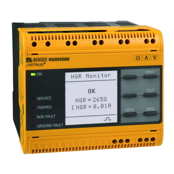
Mounting Mounting Only qualified personnel are permitted to carry out the work necessary to install, commission and run a device or system. DANGER Risk of electrocution due to electric shock! Touching live parts of the system carries the risk of: •... - Page 13 NGRM500 (HRG) / NGRM550 (LRG) Enclosure view NGRM500 Ground fault NGR fault Trip NGRM500 Ω A V ® LINETRAXX MENU NGR Monitor RESET TEST NGR = 265 W 11 12 14 21 22 24 31 32 34 SERVICE TRIPPED I NGR = 0,01A...
- Page 14 Mounting DIN rail mounting Fix the mounting clips delivered with the device as illustrated. Snap the device on the DIN rail. Press the device lightly onto the DIN rail. Fix the device to the DIN rail by pushing the mounting clips until they you hear them click into place.
-
Page 15: Connection
NGRM500 (HRG) / NGRM550 (LRG) Connection Connection requirements Only qualified personnel are permitted to carry out the work necessary to install, commission and run a device or system. DANGER Risk of electrocution due to electric shock! Touching live parts of the system carries the risk of: •... -
Page 16: Recommended Connecting Cable Coupling Device Cd
Connection Recommended connecting cable coupling device CD… CD… Connection CD… Cable lug Metrical Imperial CD1000 N, G1, G — 1.5 mm² AWG 16 N, R — 1.5 mm² AWG 16 CD1000-2 # 1 .5 mm² AWG 16 or bigger G1, G —... - Page 17 NGRM500 (HRG) / NGRM550 (LRG) Connection with Pulser Cirquit breaker Ground fault NGR fault Trip Figure 4-2: Connection with pulser The “N” connection of the CD-series coupling device should be as close to the transformer star point as possible. An intermediate relay may be required between the power contactor of the pulser and the digital output...
- Page 18 Connection Artificial neutral (delta connection) If no star point is available, the following circuit can create an artificial neutral. Cirquit breaker Ground fault NGR fault Trip Figure 4-3: Artificial neutral with a zigzag transformer NGRM5xx_D00373_08_M_XXEN/02.2024...
-
Page 19: Connection Current Transformer
NGRM500 (HRG) / NGRM550 (LRG) Connection current transformer Choose a measuring current transformer suitable for the network to be monitored. All common measuring current transformers (50 mA or 5 A on the secondary side) can be used. The following table helps you with the... -
Page 20: Connection Of Relays
Connection Connection of relays Groud-fault relay NGR-fault relay Trip relay The delay times of the various relays are not the same. See table “Trip times”, Page 42. Connection to the X1 interface Pin assignment X1 interface I1 Digital 1 (configurable: pulser, NGR method) I2 Reset IN I3 Test IN A Modbus RTU (A) -
Page 21: X1: Output Q1
NGRM500 (HRG) / NGRM550 (LRG) 4.7.2 X1: Output Q1…2 Internal 24 V Connection to SPS External supply e. G. 12...24 V Connection to Q1, Q2: external relay or PLC Observe maximum current values! The maximum output current on X1(+24 V) is 100 mA. -
Page 22: X1: Analogue Output
Connection 4.7.3 X1: Analogue output Analogue output Mode Permissible load Current output 0…20 mA ≤ 600 4…20 mA ≤ 600 0…400 DA ≤ 4 k Voltage output 0…10 V ≥ 1 k 2…10 V ≥ 1 k Either NGR current I or NGR resistance R can be assigned to the analogue output. -
Page 23: User Interface
NGRM500 (HRG) / NGRM550 (LRG) User interface Operating elements Figure 5-1: Display elements and device buttons Display elements Operation LED (green) on: power supply available SERVICE LED on: device fault, connection fault, or maintenance mode TRIPPED LED on: trip relay tripped due to NGR fault, ground fault or device error... -
Page 24: Standard Display
User interface Standard display The pulse symbol in the lower part of the display indicates that the resistance of the is actively measured. Return from any (sub)menu to the standard display by pressing and holding ESC for more than 2 s. Fault indication (active) An active fault is indicated on the display with a warning triangle while the upper... -
Page 25: Acknowledging A Fault Message
NGRM500 (HRG) / NGRM550 (LRG) Acknowledging a fault message In order to return to the standard display of the NGR monitor, the fault message must be acknowledged by means of the RESET button. Fault messages can only be reset when the cause of fault has been eliminated. -
Page 26: Menu
Menu Menu Overview 1. Data meas. values 2. Harmonics 3. History History, Delete 4. Pulser Pulser, t Impuls 5. Display NGR, (L-L), f, I NGR no m NGR nom, 6. HRG settings CT primary, CT secondary, CT connection Method, Filter, Filter type, Filter size, Ignore values System Mode, Relay test settings... -
Page 27: Navigating Through The Menu
NGRM500 (HRG) / NGRM550 (LRG) Navigating through the menu ˄ / ˅ Select submenu. ˃ / OK Enter submenu. ˂ / ESC Return from submenu to main menu. ESC (2 s) Return to standard display. Changing settings Enter settings with text/numbers directly. There is a corresponding representation in the menu items: ˄... -
Page 28: Harmonics (Menu 2)
Menu Parameter Explanation Neutral voltage; RMS value (for selected harmonic frequency range) harm Neutral voltage; relative RMS value (for selected harmonic frequency range) harm rel Relative measured values always indicate the ratio of the measured value to the nominal value in %. The selected harmonics are configured in menu 6.4. -
Page 29: Display (Menu 5)
NGRM500 (HRG) / NGRM550 (LRG) (menu 4.2) pulse The pulse period can be set between 1…10 s. The set pulse period is only effective if the pulser (menu 4.1) is not “inactive”. The following diagram shows an overview of the pulser control:... - Page 30 Menu CT (Current Transformer, menu 6.2) Menu Parameter Setting range Explanatory notes 6.2.1 CT primary 1…10,000 Ratio of the CT on the primary side 6.2.2 CT secondary 1…10,000 Ratio of the CT on the secondary side 6.2.3 CT connection 5 A, 50 mA Used CT connection NGR (menu 6.3) Menu...
- Page 31 NGRM500 (HRG) / NGRM550 (LRG) Diagram for selecting the NGR method Figure 6-2: Configuration Digital 1 as NGR method Response values (menu 6.4) Behaviour of the trip relay in the event of a ground fault Set whether a ground fault (response value violation U and/or I ) should switch the trip relay or not.
- Page 32 Menu Restart of the installation (restart attempts) Set whether the installation should be restarted manually or automatically after a fault. a) Restart installation manually (alarm stored “on”) In the event of a fault, the trip relay changes state and the installation shuts down. The fault must be eliminated and the installation is restarted via a manual reset (menu 9) or via input I2.
- Page 33 NGRM500 (HRG) / NGRM550 (LRG) Menu Menu Parameter Setting range Explanatory notes 6.4.8 6.4.7 Alarm storedt Triggered trip relay must be reset manually (RESET or input I2) Automatic restart attempts after trestart has elapsed (max. number like setting “Number restart”) 6.4.9...
- Page 34 Menu Menu Parameter Setting range Explanatory notes 6.5.4 Analogue Mode (6.5.4.1) 0…20 mA 4…20 mA 0…400 DA 0…10 V 2…10 V Function (6.5.4.2) 6.5.5 Digital Device OUT (6.5.5.1) Fail-safe, inputs/ non-fail-safe Pulser OUT (6.5.5.2) outputs Digital 1 (6.5.5.3) Active high Active high: Activation of the function when configurable Pulser/ input level changes from “low”...
-
Page 35: Device Settings (Menu 7)
NGRM500 (HRG) / NGRM550 (LRG) 6.10 Device settings (menu 7) Further information on the configurable parameters can be found following the overview in the table. Device settings overview (menu 7) Menu Parameter Note Language German English GB English US Spanish... - Page 36 7.4), Page 39 Password Password (7.5.1) Factory setting 0000 Status (7.5.2) on, off Factory settings Discarded changes and reset to factory settings. Software Update via interface (7.7.1) see Software (menu 7.7), Page 39 UPDATE (7.7.2) Service For Bender service only NGRM5xx_D00373_08_M_XXEN/02.2024...
- Page 37 NGRM500 (HRG) / NGRM550 (LRG) Summer time (menu 7.2.3) No automatic change between summer time and standard time. Daylight Saving Time Automatic change between summer time and standard time according to North American regulation. North American summer time begins on each second Sunday in March at 02:00 local time by setting the clock forward by one hour from 02:00 to 03:00 local time.
- Page 38 Menu DNS server (menu 7.3.2.5) If a DNS server is used, enter the server's IP address. For questions regarding the configuration of a DNS server, please contact your network administrator. Domain (menu 7.3.2.6) Enter the domain. For questions regarding the configuration of the domain, please contact your network administrator.
-
Page 39: Commissioning (Menu 8)
NGRM500 (HRG) / NGRM550 (LRG) Display (menu 7.4) Brightness (menu 7.4.1) Adjust the display brightness between 0…100 % in steps of 10. If no button is pressed for 15 minutes, the display brightness decreases. After pressing a button, the display returns to the adjusted brightness. -
Page 40: Alarm (Menu 10)
Menu 6.13 Alarm (menu 10) Ackowledge Mute buzzer, delete message from the standard display, fault message remains stored in the history memory. If the installation is de-energized, no restart attempts will take place. Reset Mute buzzer, delete message from the standard display, fault message remains stored in the history memory. -
Page 41: Commissioning
NGRM500 (HRG) / NGRM550 (LRG) Commissioning The following parameters must be entered for initial commissioning: • System voltage U (phase-to-phase) The corresponding coupling device must be used depending on the system voltage:: for U T 4.3 kV: CD1000, CD1000-2, CD5000 (20 kW) for U >... -
Page 42: Output Relays Operating Modes
Commissioning For jumping measured values in systems with frequency converters, a filter can be switched on. The switch-off time for R is extended by the filter time and can be up to one minute. Output relays operating modes The factory setting for the relays is fail-safe. In the case of a device test, the relays change state. The settings can be changed in menu 6.5.1…6.5.6 (see “System settings (menu 6.5)”, Page 33). - Page 43 NGRM500 (HRG) / NGRM550 (LRG) Maximum trip times t(GFtrip) for the used CD-NGRM Coupling device Ground-fault max. t GF Trip trip setting 400… 690 V CD1000 on or off 48 h CD1000-2 on or off 48 h 691…1000 V CD1000...
-
Page 44: Rms Trip Signal, Fundamental, Harmonics
Commissioning NGR fault relay timing diagram Figure 7-2: NGR fault relay timing diagram ADVICE The NGR fault detection of <7.5 s can extend to minutes by using the NGR filter, depending on the setting. RMS trip signal, fundamental, harmonics The measured value which causes tripping can be selected via the “Trip signal” parameter (menu 6.4). Trip signal can be: The RMS value of current or voltage over the entire frequency range (up to approx. -
Page 45: Filter Ngr Measurement
NGRM500 (HRG) / NGRM550 (LRG) Filter NGR measurement Parameter Filter NGR measurement Filter weak medium strong customized Filter type – Average value Average value Average value, Filter size – 2...40 Ignore values – 0...10 Initial measurement During device start, all measured values are recorded. -
Page 46: Interfaces
Interfaces Interfaces Analogue output (menu 6.5.4) Either NGR current I or NGR resistance R (HRG devices only) can be assigned to the analogue output. A voltage or current signal proportional to the measured value is applied to the output. The following settings are possible: Mode (menu 6.5.4.1) •... -
Page 47: Digital Input
NGRM500 (HRG) / NGRM550 (LRG) Use of Q2: Pulser Mode Inactive Active Fail-safe energized de-energized Q2 low Q2 high Non-failsafe de-energized energized Q2 high Q2 low Digital input The input is only detected as “activated” after the contact has been activated for at least 150 ms. This way, short interference pulses are ignored. -
Page 48: Test Cycle
Test cycle Test cycle Since the relays are not monitored in the hardware or software, the relays must be tested at regular intervals on proper functioning. The frequency of the test cycle is subject to the safety requirements of the operator but it must be carried out at least every six months. -
Page 49: Technical Data
NGRM500 (HRG) / NGRM550 (LRG) Technical data 10.1 Factory settings Menu Factory settings Menu 6.1: HRG/LRG system 1. U (L-L) 400 V 2. CD-NGRM CD1000 3. Frequenz 50 Hz 4. I NGR nom 5. R NGR nom Menu 6.2: CT 1. - Page 50 Technical data Menu Factory settings Menü 6.5: System settings 1. Ground-fault relay Mode fail-safe Rel. test 2. NGR relay Mode fail-safe Rel. test 3. Trip relay Mode fail-safe Rel. test 4. Analogue Mode 4...20 mA Function R NGR (HRG) I NGR (LRG) 5.
-
Page 51: Error Codes
NGRM500 (HRG) / NGRM550 (LRG) 10.2 Error codes Error code/ Description/Cause Action Service code 6.10 Error during field calibration Restart field calibration. If the error persists, contact service. 6.11 Field calibration could not be started The installation must operate error-free before starting a field calibration. -
Page 52: Technical Data Ngrm500/550
Technical data 10.3 Technical Data NGRM500/550 Insulation coordination according to IEC 60664-1/IEC 60664-3/DIN EN 50178 Definitions Supply circuit (IC1) (A1, A2) Measuring circuit/Control circuit (IC2) (RS, E, CT), (X1, ETH) Output circuit 1 (IC3) (11, 12, 14) Output circuit 2 (IC4) - Page 53 NGRM500 (HRG) / NGRM550 (LRG) Supply voltage U Nominal supply voltage AC/DC, 48…240 V for UL applications AC/DC, 48…240 V for AS/NZS 2081 applications AC/DC, 48…230 V Tolerance ±15 % for UL applications –50…+15 % for AS/NZS 2081 applications –25…+20 % Frequency range DC, 40…70 Hz...
- Page 54 Technical data Monitoring I Measuring circuit 5 A Frequency ranges 50/60 Hz 10…3200 Hz Nominal measuring current I Maximum continuous current 2 x I Overload capacity 10 x I for 0.03 s Measurement accuracy ±2 % von I Load 10 m Measuring circuit 50 mA Frequency ranges 50/60 Hz...
- Page 55 NGRM500 (HRG) / NGRM550 (LRG) Monitoring U Frequency ranges 50/60 Hz 10…3200 Hz with R (400/]3) … C (4300/]3) V = 20 k with R > (4.3 /]3) … (25/]3) kV = 100 k Measuring range 1.2 x U NGR nom...
- Page 56 Technical data Analogur output (M+) Operating principle linear Functions Current 0…20 mA (≤ 600 ), 4…20 mA (≤ 600 ), 0…400 A (≤ 4 k ) Voltage 0…10 V (≥ 1 k ), 2…10 V (≥ 1 k ) Tolerance related to the current/voltage end value ±20 % Ground-fault, NGR, trip relay Switching elements...
- Page 57 NGRM500 (HRG) / NGRM550 (LRG) Classification of mechanical conditions acc. to IEC 60721 / IEC 60255-21 / DIN EN 60068-2-6 Stationary use 3M12 Transport Long-term storage 1M12 Connection with Screw-type terminals Tightening torque 0,5…0,6 Nm (5…7 lb-in) Stripping length 7 mm...
-
Page 58: Standards, Approvals, Certifications
Standards, approvals, certifications The specified standards take into account the edition valid until 09.2021 unless otherwise indicated. UL File Number: E493737, E173157 EU Declaration of Conformity The EU Declaration of Conformity is available at the following Internet address: https://www.bender.de/fileadmin/content/Products/CE/CEKO_NGRM.pdf NGRM5xx_D00373_08_M_XXEN/02.2024... -
Page 59: Ordering Details
NGRM500 (HRG) / NGRM550 (LRG) 10.5 Ordering details 10.5.1 NGR Monitor NGR Monitor Type Supply voltage/Frequency range U Art. No. NGRM500 AC 48…240 V, 40…70 Hz B94013500 DC 48…240 V NGRM550 B94013550 10.5.2 Accessories Measuring current transformers Frequency/Ground-fault current Type Art. - Page 60 Technical data CD series coupling device Voltage U Type Art. No. 400…690 V CD1000 B98039010 400…1000 V CD1000-2 B98039053 1000…4200 V CD5000 B98039011 4300…14550 V CD14400 B98039054 14551…25000 V CD25000 B98039055 NGRM5xx_D00373_08_M_XXEN/02.2024...
-
Page 61: Document Revision History
NGRM500 (HRG) / NGRM550 (LRG) 10.6 Document revision history Date Version State/Changes 04-2021 Editorial revision Distinction between “system” and “device” Deleted W…AB measuring current transformers (discontinued) 02-2022 Added LRG variant NGRM550; Digital input I1 switchable Editorial revision Several error corrections... - Page 62 Glossary Glossary Coupling Device CD-series Current Transformer Fast Fourier Transformation Human Machine Interface, display unit High Resistance Grounding NGR rated current Nominal current through the NGR NGR nom Low Resistance Grounding Neutral Earthing Resistor (NER = NGR) Neutral Grounding Resistor Network Time Protocol Potential Transformer NGR resistance value...
- Page 64 Bender GmbH & Co. KG • Germany Canada • Missisauga ON, Canada Londorfer Straße 65 • 35305 Grünberg 800.243.2438 / 905.602.9990 All rights reserved. Tel.: +49 6401 807-0 • info@bender.de info@bender-ca.com Reprinting and duplicating only www.bender.de www.bender-ca.com with permission of the publisher.
Need help?
Do you have a question about the NGRM500 and is the answer not in the manual?
Questions and answers