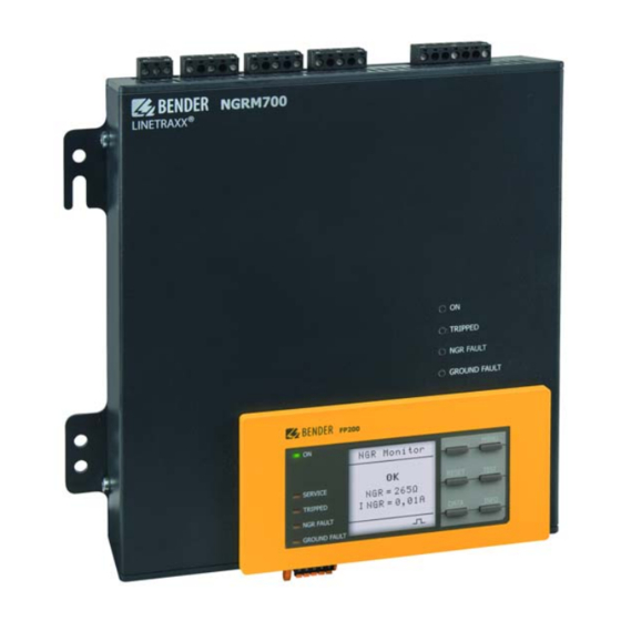
Bender NGRM700 Manual
Neutral grounding resistor monitor
Hide thumbs
Also See for NGRM700:
- Manual (80 pages) ,
- Quick start manual (9 pages) ,
- Quick start manual (8 pages)

Related Manuals for Bender NGRM700


Summary of Contents for Bender NGRM700
- Page 1 NGRM700 (HRG) NGRM750 (LRG) Neutral Grounding Resistor Monitor NGRM7xx_D00292_07_M_XXEN/02.2022 Manual...
- Page 2 Bender GmbH & Co. KG Londorfer Str. 65 • 35305 Grünberg • Germany PO Box 1161 • 35301 Grünberg • Germany Tel.: +49 6401 807-0 • Fax: +49 6401 807-259 E-Mail: info@bender.de • www.bender.de © Bender GmbH & Co. KG All rights reserved.
-
Page 3: Table Of Contents
Glossary ....................... 13 3. Function ....................14 Device features ....................14 Functional description ................... 15 NGRM700: Recommended minimum value RNGR (tripping level 50 %) ..................... 16 3.3.1 Recommended RNGR for system voltage Usys ≤ 4300 V (HRG system) ...................... 16 3.3.2... - Page 4 Table of Contents Dimension diagrams ..................18 4.2.1 Dimension diagram FP200-NGRM ............18 4.2.2 Dimension diagram NGRM7… ..............19 Enclosure view ....................20 Removing FP200-NGRM from enclosure ..........20 Door mounting ....................21 Front cover for FP200-NGRM ..............21 5. Connection ..................... 22 Connection requirements ................
- Page 5 Table of Contents Changing settings ................... 39 Data measured values (menu 1) ..............40 Harmonics (menu 2) ..................41 History (menu 3) ....................41 Pulser (menu 4) ....................42 Display (menu 5) ....................42 HRG, LRG settings (menu 6) ................. 43 7.9.1 HRG, LRG system (menu 6.1) ...............
- Page 6 Table of Contents 10. Test cycle ....................65 11. Factory settings ................... 66 12. Error codes ................... 68 13. Technical data ..................69 13.1 Tabular data ....................... 69 13.2 Standards, approvals, certifications ............74 13.3 Ordering details ....................75 13.3.1 NGR monitor ...................... 75 13.3.2 Accessories ......................
-
Page 7: Important Information
This manual has been compiled with great care. It might nevertheless contain errors and mistakes. Bender cannot accept any liability for injury to persons or damage to property resulting from errors or mistakes in this manual. -
Page 8: Technical Support: Service And Support
Repair, calibration, testing and analysis of Bender products Hardware and software update for Bender devices Delivery of replacement devices for faulty or incorrectly delivered Bender devices Extended warranty for Bender devices with in-house repair service or replacement ... -
Page 9: Field Service
ZVEI (Zentralverband Elektrotechnik- und Elektronikindustrie e.V., (German Elec- trical and Electronic Manufacturers' Association) also applies. Conditions of sale and delivery can be obtained from Bender in printed or electronic for- mat. 1.5 Inspection, transport and storage Inspect the dispatch and equipment packaging for damage, and compare the contents of the package with the delivery documents. -
Page 10: Warranty And Liability
13th August 2005 must be taken back by the manufacturer and disposed of properly. For more information on the disposal of Bender devices, refer to our homepage at www.bender.de > Service & support. -
Page 11: Safety Instructions
2.1 General safety instructions Part of the device documentation in addition to this manual is the enclosed "Safety in- structions for Bender products". 2.2 Work activities on electrical installations Only qualified personnel are permitted to carry out the work necessary to install, commission and run a device or system. -
Page 12: Intended Use
Safety instructions 2.3 Intended use The NGRM700 is only intended for use in high-resistance grounded systems. The NGRM750 is only intended for use in low-resistance grounded systems. In these systems, the NGRM7… monitors the current through the neutral grounding resistor (NGR), ... -
Page 13: Glossary
Safety instructions 2.4 Glossary Coupling Device CD-series Current Transformer Fast Fourier Transformation Human Machine Interface, display unit High Resistance Grounding NGR rated current Nominal current through the NGR NGR nom Low Resistance Grounding Neutral Earthing Resistor (NER = NGR) Neutral Grounding Resistor Network Time Protocol Potential Transformer NGR resistance value... -
Page 14: Function
Function 3. Function 3.1 Device features Determination of R with passive and active measurement methods Continuous monitoring of the R even if the installation is de-energized; Alarm or trip on ground fault Monitoring of the current I ... -
Page 15: Functional Description
"passive" when the measured current or voltage value exceeds or falls below the internal threshold. The threshold is 15 % of the nominal value and can be adjusted by Bender if required. A shorted or open NGR is reliably detected in an energized as well as a de-energized in- stallation with the active measurement method. -
Page 16: (Tripping Level 50 %)
Function 3.3 NGRM700: Recommended minimum value (tripping level 50 %) Temperature range –40…+70 °C, field calibration at 20 °C () = Limited temperature range at any field calibration temperature ±20 K The temperatures must be within the limits of the operating temperature range of –40…+70 °C [–40…+60 °C for UL applications]. -
Page 17: (Hrg System)
Function 3.3.2 Recommended for system voltage > 4300 V (HRG system) CD14400 CD25000 6000 V 6600 V 7200 V 11000 V 14400 V 25000 V — — — — — — 693 Ω 762 Ω 831 Ω 1270 Ω 1663 Ω —... -
Page 18: Mounting
Mounting 4. Mounting Only qualified personnel are permitted to carry out the work necessary to install, commission and run a device or system. Risk of electrocution due to electric shock! Touching live parts of the system carries the risk of: An electric shock ... -
Page 19: Dimension Diagram Ngrm7
Mounting 4.2.2 Dimension diagram NGRM7… 3 (0.12) Mounting position 205 (8.07) 211 (8.31) 230 (9.06) 245 (9.65) Abb. 4.2: Dimension diagram and mounting position NGRM7…; mm(in) NGRM7xx_D00292_07_M_XXEN/02.2022... -
Page 20: Enclosure View
Mounting 4.3 Enclosure view A1 A2 11 12 14 21 22 24 31 32 34 NGRM700 ® LINETRAXX Front TRIPPED NGR FAULT GROUND FAULT FP200 MENU TEST RESET SERVICE < TRIPPED INFO DATA NGR FAULT GROUND FAULT R on/off Bottom... -
Page 21: Door Mounting
Mounting 4.5 Door mounting *IP 65: 68+0,7/-0 mm 0,3 Nm ± 10 % Remote: max. 5 m MENU RESET TEST SERVICE < TRIPPED INFO DATA NGR FAULT GROUND FAULT RJ45: Switch Remote RJ45: Ethernet TRIPPED NGR FAULT GROUND FAULT Fig. 4.5: Door mounting 4.6 Front cover for FP200-NGRM B98060005 When installed in doors, the degree of protec-... -
Page 22: Connection
Connection 5. Connection 5.1 Connection requirements Only qualified personnel are permitted to carry out the work necessary to install, commission and run a device or system. Risk of electrocution due to electric shock! Touching live parts of the system carries the risk of: An electric shock ... -
Page 23: Connection Descriptions Of Cd-Series Coupling Device
Connection 5.2 Connection descriptions of CD-series coupling device Connection to star point G1, R Connection to R of the NGRM7… CD1000-2 CD1000 CD14400 G, E Connection to E of the NGRM7… CD5000 CD25000 and to the protective earth con- ductor of the installation (PE) NGRM7xx_D00292_07_M_XXEN/02.2022... -
Page 24: Star Connection
Connection 5.3 Star connection 5.3.1 Connection ≤ 690 V For these voltages, the phase monitor of the NGRM7… can be connected directly to the phase conductors to be monitored. Circuit breaker Ground fault NGR fault Trip 11 12 14 21 22 24 31 32 34 NGRM7…... -
Page 25: Connection Usys ≤ 690 V With Pulser
Connection 5.3.2 Connection ≤ 690 V with pulser Circuit breaker Ground fault NGR fault Trip 11 12 14 21 22 24 31 32 34 NGRM7… LINETRAXX® AC/DC 48...240 V CD... (G1) E (G) Ethernet Pulser Fig. 5.2: Connection U ≤ 690 V with pulser The "N"... -
Page 26: Connection Usys ≤ 690 V
Connection 5.3.3 Connection > 690 V For these voltages, the phase monitor of the NGRM7… can only be connected to the conductors to be monitored via potential transformers (PT). Circuit breaker PT * Ground fault NGR fault Trip 11 12 14 21 22 24 31 32 34 NGRM7…... -
Page 27: Artificial Neutral (Delta Connection)
Connection 5.3.4 Artificial neutral (delta connection) If no star point is available, the following circuit can create an artificial neutral. Connection with a zigzag transformer Circuit breaker Ground fault NGR fault Trip 11 12 14 21 22 24 31 32 34 NGRM7…... -
Page 28: Ct Connection
5…25 A 5…1000 A 0…3800 Hz 42…3800 Hz 50/60 Hz Measuring range (see Transformation ratio CTUB103 manual) Bender measuring 5 A 100:1 600:1 current transformer 10 A 200:1 25 A 500:1 max. 30 m max. 40 m max. 25 m Length (4 mm²/AWG12) -
Page 29: Connection Of Relays (Ground-Fault, Ngr And Trip Relay)
Connection 5.5 Connection of relays (ground-fault, NGR and trip relay) Ground-fault relay NGR-fault relay Trip relay Fig. 5.5: Connection of relays 5.6 Connection to the X1 interface Digital 1 (configurable: pulser, NGR method) Reset IN Test IN Modbus RTU (A) Modbus RTU (B) Common Analogue output... -
Page 30: X1: Input I1
Connection 5.6.1 X1: Input I1…3 The input is only detected as "activated" after the contact has been activated for at least 150 ms. This way, short interference pulses are ignored. Active high Active low I1…3 I1…3 open open Switch Switch closed closed Digital 1,... -
Page 31: X1: Output Q1
Connection 5.6.2 X1: Output Q1…2 Internal 24 V Connection to PLC +24 V, +24 V, max. 100 mA max. 100 mA Pull up Pull up 10 kΩ 10 kΩ max. 300 mA, 24 V FP200-NGRM FP200-NGRM External supply e.g.12...24 V +24 V, max. -
Page 32: X1: Analogue Output
Connection 5.6.3 X1: Analogue output Analogue output Mode Permissible load Current output 0…20 mA ≤ 600 Ω 4…20 mA ≤ 600 Ω 0…400 μA ≤ 4 kΩ Voltage output 0… 10 V ≥ 1 kΩ 2… 10 V ≥ 1 kΩ Either NGR current I or NGR resistance R can be assigned to the analogue out-... -
Page 33: User Interface Fp200-Ngrm
User interface FP200-NGRM 6. User interface FP200-NGRM FP200 MENU RESET TEST SERVICE < TRIPPED INFO DATA NGR FAULT GROUND FAULT Legend, FP200-NGRM No. Description Explanation Display elements Operation LED, green; on when power supply is available The LC display shows device and measurement information. The LED is on when there is either a device fault or a connection SERVICE fault, and when the device is in maintenance mode. - Page 34 User interface FP200-NGRM No. Description Explanation Device buttons Navigates up in a list or increases a value. MENU Opens the device menu. Cancels the current process or navigates one step back in the device menu. RESET Resets alarms. Navigates backwards (e.g. to the previous setting step) or selects <...
-
Page 35: Standard Display
User interface FP200-NGRM 6.1 Standard display FP200 MENU NGR Monitor RESET TEST NGR = 265Ω SERVICE I NGR = 0,01A TRIPPED INFO DATA NGR FAULT GROUND FAULT The pulse symbol in the lower part of the display indicates that the resistance of the R is actively measured. -
Page 36: Fault Indication (Inactive)
User interface FP200-NGRM 6.3 Fault indication (inactive) FP200 MENU UNGR(rms) Limit 269 V RESET TEST SERVICE 03.01.17 12:38 TRIPPED 03.01.17 12:38 DATA NGR FAULT GROUND FAULT An inactive fault is indicated on the display with a . If more than one fault has oc- curred, the number of faults is also indicated in the lower part of the display. -
Page 37: History Memory
User interface FP200-NGRM 6.5 History memory Up to 1023 alarm messages and device errors with date and time stamp can be stored in the history memory. If the maximum number of memory entries has been reached, the oldest entry will be overwritten by a new event record. Display the history memory at MENU >... -
Page 38: Menu
Menu 7. Menu 7.1 Overview , Method, R NGR rel sense, rms rel rms rel, fund 1. Data meas. values fund rel fund fund rel, harm harm rel harm harm rel, L1L2 L2L3 , f, U L3L1 1-E rms 2-E rms 3-E rms 2. -
Page 39: Navigating Through The Menu
Menu 7.2 Navigating through the menu Select a submenu using the buttons and press OK. Return from any submenu to the main menu by pressing ESC or < Return from any (sub)menu to the standard display by pressing and holding ESC for more than 2 s. 7.3 Changing settings Enter settings with text/numbers directly on the FP200-NGRM. -
Page 40: Data Measured Values (Menu 1)
Menu 7.4 Data measured values (menu 1) Navigate through the list of current measured values using the buttons. Parameter Description NGR resistance value NGR relative resistance value NGR rel Method Measurement method (see menu 6.3) Resistance value; CD-series coupling device Sense Current;... -
Page 41: Harmonics (Menu 2)
Menu Note Relative measured values always indicate the ratio of the measured value to the nominal value. The selected harmonics are configured in the menu 6.5. 7.5 Harmonics (menu 2) The measured harmonics are represented in a bar graph as a percentage of the meas- ured value in relation to the nominal value. -
Page 42: Pulser (Menu 4)
Menu 7.7 Pulser (menu 4) A ground fault can be located by means of a measuring clamp-on ammeter and the pulser function. The pulser relay is designed as Open Collector. Pulser (menu 4.1) Active - The pulser is continuously active regardless of ground faults that have ... -
Page 43: Hrg, Lrg Settings (Menu 6)
Menu 7.9 HRG, LRG settings (menu 6) 7.9.1 HRG, LRG system (menu 6.1) Menu Parameter Setting range Explanatory notes 6.1.1 400 V…25 kV System phase-to-phase voltage sys (L-L) For CD1000 and CD1000-2, select "CD1000" in CD1000, CD5000, the menu. CD14400 6.1.2 CD-NGRM The selection depends on the system voltage... -
Page 44: Ngr (Menu 6.3)
Menu 7.9.3 NGR (menu 6.3) Menu Parameter Setting range Explanatory notes auto: automatic changeover between active and passive resistor monitoring; setting for field calibration passive: only passive resistor monitoring (see page 15) auto, passive, 6.3.1 Method external: If "Digital 1 > NGR method" (menu 6.6.5.3) external is set, switching takes place depending on the con- dition of the digital input I1:... -
Page 45: Phase Monitor (Menu 6.4)
Menu 7.9.4 Phase monitor (menu 6.4) When phase-voltage monitoring is used, the faulted phase can be determined in the event of a ground fault. Menu Parameter Setting range Explanatory notes on: enable function 6.4.1 Phase monitor on, off off: disable function (despite wiring, the faulted phase is not signalled) Ratio of the potential transformer on 6.4.2... - Page 46 Menu Restart of the installation (restart attempts) Restart of the installation (restart attempts) Set whether the installation should be restarted manually or automatically after a fault. a) Restart installation manually (alarm stored "on") In the event of a fault, the trip relay changes state and the installation shuts down.
- Page 47 Menu Response values For the delay times, see also page 60. Menu Menu Parameter Setting range Explanatory notes trip Value in % of the nominal value at which 6.5.1 10…90 % the trip relay and the ground-fault relay trip. Note: The trip relay only trips if trip 6.5.2 10…90 %...
- Page 48 Menu Menu Menu Parameter Setting range Explanatory notes Time delay between fault elimination restart and automatic restart of the installation; On the 6.5.9 6.5.8 100 ms…24 h only used when "Alarm stored > off" has device: been selected. t(restart) Number of restart attempts within 24 h; 6.5.10 6.5.9 Restart count 1…5 only used when "Alarm stored >...
-
Page 49: System Settings (Menu 6.6)
Menu 7.9.6 System settings (menu 6.6) Setting Menu Parameter Explanatory notes range Fail-safe, Mode (6.6.1.1) Ground- non-fail-safe 6.6.1 fault relay Relay test (6.6.1.2) on, off Fail-safe, Mode (6.6.2.1) NGR-fault non-fail-safe 6.6.2 relay Relay test (6.6.2.2) on, off Fail-safe, Mode (6.6.3.1) non-fail-safe 6.6.3 Trip relay Relay test (6.6.3.2) on, off... -
Page 50: Field Calibration (Menu 6.7)
Menu Legend, Tab. 7.7 Fail-safe: The relay is energized during normal operation and is de-energized in the event of a fault ("fail-safe") Non-fail-safe: The relay is de-energized in normal operation and is energized in the event of a fault ("non-fail-safe") When set to "on", the function of the relay is checked during a test by switching it. -
Page 51: Device Settings (Menu 7)
Menu 7.10 Device settings (menu 7) Further information on the configurable parameters can be found following the over- view in the table. Menu Parameter Note German English GB Language English US Spanish French Time (7.2.1) Set local time 12 h (am/pm) Format (7.2.2) 24 h Summer time (7.2.3) - Page 52 Factory settings factory settings Update via interface Software UPDATE Service For Bender service only Tab. 7.8: Device settings overview (menu 7) Explanatory notes Tab. 7.8 Summer time (menu 7.2.3) No automatic change between summer time and standard time. Daylight Saving Time Automatic change between summer time and standard time according to North American regulation.
- Page 53 Menu NTP (menu 7.2.6) Synchronisation via NTP server is enabled. To use this function, configure the NTP server. Synchronisation is disabled. UTC (menu 7.2.8) Set the time according to UTC (Coordinated Universal Time). For Germany, set +1 for winter- time (MEZ) and +2 for summer time (MESZ). Interface (menu 7.3) Set the parameters for connecting other communication devices in the interface menu: Write access (menu 7.3.1)
- Page 54 Menu IP (menu 7.3.2.2) Set the appropriate IP address for the NGRM7… SN (menu 7.3.2.3) Set the appropriate subnet mask. Std. GW (menu 7.3.2.4) If a standard gateway is used, enter the IP address here. DNS server (menu 7.3.2.5) If a DNS server is used, enter the server's IP address. For questions regarding the configura- tion of a DNS server, please contact your network administrator.
-
Page 55: Commissioning (Menu 8)
Menu Modbus RTU (menu 7.3.5) Settings for communication with other devices via Modbus RTU. Address (menu 7.3.5.1): 1…247 Baud rate (menu 7.3.5.2): the selectable options are 6 kbaud, 19.2 kbaud, 38.4 kbaud, 57.6 baud ... -
Page 56: Info (Menu 9)
Menu 7.12 Info (menu 9) The current settings of the NGRM7… can be viewed in the Info menu. Navigate through the different views using the arrow buttons: Device name, serial number, article number Software Measurement equipment software version, HMI software version Clock Time, date, summer time Ethernet... -
Page 57: Initial Commissioning
Initial commissioning 8. Initial commissioning The following parameters must be entered for initial commissioning: System voltage U (phase-to-phase) The corresponding coupling device must be used depending on the system voltage: for U ≤ 4.3 kV: CD1000, CD1000-2, CD5000 (20 kΩ) for U >... -
Page 58: Output Relays Operating Modes
Initial commissioning Resistance trip threshold ( Both trip thresholds for the resistance are set as a percentage of the nominal NGR. Set- ting range of trip threshold R 10…90 % (factory setting 50 %) 110…200 % (factory setting 200 %). The upper trip threshold for the resistance is set in Ω. - Page 59 Initial commissioning Explanatory notes on trip relay 1. In case of a ground fault, t is only considered when "Ground-fault trip" (menu 6.5) is ena- GF trip bled. When "Ground-fault trip" is disabled, the trip relay does not switch in the event of a ground fault.
- Page 60 Initial commissioning Ground-fault relay timing diagram Ground fault Ground fault Ground-fault relay Trip relay 40 ms = 100 ms...48 h,∞ GF Trip Fig. 8.1: Ground-fault relay timing diagram NGR-fault relay timing diagram NGR fault NGR fault NGR-fault relay Trip relay <...
-
Page 61: Rms Trip Signal, Fundamental, Harmonics
Initial commissioning 8.3 RMS trip signal, fundamental, harmonics The measured value which causes tripping can be selected via the "Trip signal" parameter (menu 6.5). Trip signal can be: The RMS value of current or voltage over the entire frequency range (up to approx. 3.8 kHz). - Page 62 Initial commissioning Timing diagram device start Ground fault/ NGR fault Supply Power Trip relay energized de-energized fail-safe de-energized Trip relay de-energized energized non-fail-safe Initial GF Trip Boot Time Measurement Normal 9…11 s 4…6 s operation NGR Trip Fig. 8.3: Timing diagram device start NGRM7xx_D00292_07_M_XXEN/02.2022...
-
Page 63: Analogue And Digital I/O Configuration
Analogue and digital I/O configuration 9. Analogue and digital I/O configuration 9.1 Analogue output (menu 6.6.4) Either NGR current I or NGR resistance R can be assigned to the analogue out- put. A voltage or current signal proportional to the measured value is applied to the output. -
Page 64: Use Of Q1: Device Health
Analogue and digital I/O configuration 9.2.1 Use of Q1: Device health Device error No device Intern. 24 V Mode error detected detected +24 V, max. 100 mA Fail-safe Pull up energized de-energized 10 kΩ Q1 low Q1 high 24 V, max. -
Page 65: Test Cycle
Test cycle 10. Test cycle Since the relays are not monitored in the hardware or software, the relays must be test- ed at regular intervals to verify proper functioning. The frequency of the test cycle is subject to the safety requirements of the operator but it must be carried out at least every six months. -
Page 66: Factory Settings
Factory settings 11. Factory settings Menu Factory settings Menu 6.1: HRG/LRG system 1. U 400 V sys (L-L) 2. CD-NGRM CD1000 3. Frequency 50 Hz 4. I NGR nom 5. R 150 Ω NGR nom Menu 6.2: CT 1. CT primary 2. - Page 67 Factory settings Menu Factory settings 9. t 8. t restart restart 10. Restart count 9. Restart count 11. Trip signal 10. Trip signal 12. Upper limit 11. Upper limit harmonic harmonic 13. Lower limit 12. Lower limit harmonic harmonic Menu 6.6: System settings Mode fail-safe 1.
-
Page 68: Error Codes
Error codes 12. Error codes Error code/ Description/Cause Action Service code Restart field calibration. If the error 6.10 Error during field calibration persists, contact service. The installation must operate error- Field calibration could not be free before starting a field calibration. 6.11 started Restart field calibration. -
Page 69: Technical Data
Technical data 13. Technical data 13.1 Tabular data Insulation coordination according to IEC 60664-1/IEC 60664-3/DIN EN 50178 Definitions Measuring circuit 1 (IC1) ............................(L1, L2, L3) Supply circuit (IC2) ................................. (A1, A2) Measuring circuit/Control circuit (IC3)....................(RS, E, CT), (X1, Ethernet) Output circuit 1 (IC4) ..............................(11, 12, 14) Output circuit 2 (IC5) ..............................(21, 22, 24) Output circuit 3 (IC6) ..............................(31, 32, 34) - Page 70 Technical data Voltage tests (routine test) acc. to IEC 61010-1 IC2 / (IC3…6)................................AC 2.2 kV IC3 / (IC4…6)................................AC 2.2 kV IC4 / (IC5…6)................................AC 2.2 kV IC5 / (IC6)..................................AC 2.2 kV Supply voltage Nominal supply voltage U ≤ 2000 m ............................AC/DC, 24…240 V ≤...
- Page 71 Technical data Monitoring Measuring input R ..............................< 33 V RMS Measuring range NGR (with R = 20 kΩ) active ......................0…10 kΩ Measurement uncertainty for T = 0…+40 °C....................±20 Ω Measurement uncertainty for T = –40…+70 °C................... ±40 Ω Measuring range NGR (with R = 100 kΩ) active......................0…10 kΩ...
-
Page 72: Measuring Range
Technical data Tolerance t when set to trip RMS................................–20…0 ms Fundamental ........................0…+150 ms (filter time) Harmonics...........................0…+150 ms (filter time) Measuring current transformer ratio primary ......................1…10,000 Measuring current transformer ratio secondary....................... 1…10,000 Measuring range................................ 2 x I NGR nom Coupling for U ≤... - Page 73 Technical data Analogue output (M+) Operating principle ................................linear Functions..................................I Current................0…20 mA (≤ 600 Ω), 4…20 mA (≤ 600 Ω), 0…400 μA (≤ 4 kΩ) Voltage .........................0…10 V (≥ 1 kΩ), 2…10 V (≥ 1 kΩ) Tolerance related to the current/voltage end value......................±20 % Ground-fault, NGR, trip relay Switching elements............................
-
Page 74: Standards, Approvals, Certifications
Technical data Connection Screw-type terminals Tightening torque......................0.5…0.6 Nm (5…7 lb-in) Conductor sizes ............................AWG 24-12 Stripping length..............................7 mm rigid/flexible ............................0.2…2.5 mm² flexible with ferrule with/without plastic sleeve ................0.25…2.5 mm² Multiple conductor, rigid......................... 0.2…1 mm² Multiple conductor flexible ......................... 0.2…1.5 mm² Multiple conductor flexible with ferrule without plastic sleeve ............ -
Page 75: Ordering Details
Technical data 13.3 Ordering details 13.3.1 NGR monitor Supply voltage/Frequency range Type Art. No. NGRM700 B94013700 AC 24…240 V, 40…70 Hz DC 24…240 V NGRM750 B94013750 Accessory for FP200-NGRM: Transparent front cover 144x72 (for IP65)* B98060005 *When using the "transparent front cover 144x72 (IP 65)" the cutout in the switchboard cabinet must be extended in height from 66 mm to 68 mm (+0.7/-0 mm). -
Page 76: Document Revision History
Technical data Connecting cables CTUB103 Length (m) Type Art. No. CTXS-100 B98110090 CTXS-250 B98110091 CTXS-500 B98110092 CTXS-1000 B98110093 CD-series coupling device Voltage Type Art. No. 400…690 V CD1000 B98039010 400…1000 V CD1000-2 B98039053 1000…4200 V CD5000 B98039011 4300…14550 V CD14400 B98039054 14551…25000 V CD25000... - Page 77 INDEX Acknowledging a fault message 36 Enclosure view 20 Alarm 56 Error codes 68 Analogue output 63 Ethernet 53 BCOM 54 Factory settings 66 Fault indication 35 Field calibration 50 FP200-NGRM 20 CEST (Central European Summer Time) 52 Connection - Measuring current transformer 28 - Relay 29 Glossary 13 - Usys >...
- Page 78 INDEX Menu 5 42 Subsystem 54 Menu 6 43 Support 8 Menu 7 51 Menu 8 55 Menu 9 56 Technical data 69 Modbus TCP 54 Test cycle 65 Timing diagram - Ground-fault relay 60 NTP 53 - NGR relay 60 Training courses 9 Trip signal 61 Trip threshold...
- Page 80 Bender GmbH & Co. KG Londorfer Straße 65 • 35305 Grünberg • Germany Tel.: +49 6401 807-0 • info@bender.de • www.bender.de Exton PA, USA 800.356.4266 / 610.383.9200 • info@bender.org www.bender.org Canada Missisauga ON, Canada 800.243.2438 / 905.602.9990 • info@bender-ca.com www.bender-ca.com Mexico, South America, Central America, Caribbean info@bender-latinamerica.com...
Need help?
Do you have a question about the NGRM700 and is the answer not in the manual?
Questions and answers