Bender VMD420 Manual
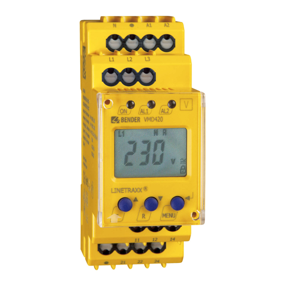
Voltage and frequency monitor for monitoring of 3(n)ac systems up to 0...500 v
Hide thumbs
Also See for VMD420:
- Manual (40 pages) ,
- Installation bulletin and reference manual (2 pages) ,
- Quick start manual (8 pages)

Related Manuals for Bender VMD420


Summary of Contents for Bender VMD420
- Page 1 Manual VMD420 Voltage and frequency monitor for monitoring of 3(N)AC systems up to 0…500 V for undervoltage, overvoltage, underfrequency, overfrequency Software version: D238 V2.2x VMD420_D00137_01_M_XXEN/05.2016...
- Page 2 Bender GmbH & Co. KG P.O. Box 1161 • 35301 Gruenberg • Germany Londorfer Strasse 65 • 35305 Gruenberg • Germany Tel.: +49 6401 807-0 • Fax: +49 6401 807-259 E-Mail: info@bender.de • www.bender.de © Bender GmbH & Co. KG All rights reserved.
-
Page 3: Table Of Contents
Table of Contents 1. Important information ..................7 How to use this manual ................. 7 Technical support: service and support ........... 8 1.2.1 First level support ..................... 8 1.2.2 Repair service ..................... 8 1.2.3 Field service ......................9 Training courses ..................... 10 Delivery conditions .................. - Page 4 Table of Contents 3.2.10 Erasable history memory ................19 3.2.11 Alarm LEDs show which relay is in the alarm state ......19 3.2.12 Starting a device using a simulated alarm S.AL ........19 4. Installation, connection and commissioning ........... 21 Fast commissioning for Un = 400 V, 50 Hz ...........
- Page 5 Table of Contents 6. Technical data ....................51 Data in tabular form ..................51 Standards, approvals and certifications ..........55 Ordering information ................... 55 INDEX ........................57 VMD420_D00137_01_M_XXEN/05.2016...
-
Page 7: Important Information
1. Important information 1.1 How to use this manual This manual is intended for qualified personnel working in electrical engineering and electronics! Always keep this manual within easy reach for future reference. To make it easier for you to understand and revisit certain sections in this man- ual, we have used symbols to identify important instructions and information. -
Page 8: Technical Support: Service And Support
Important information This manual has been compiled with great care. It might nevertheless contain errors and mistakes. Bender cannot accept any liability for injury to persons or damage to property resulting from errors or mistakes in this manual. 1.2 Technical support: service and support For commissioning and troubleshooting Bender offers you: 1.2.1... -
Page 9: Field Service
Important information Bender GmbH, Repair-Service, Londorfer Str. 65, 35305 Grünberg 1.2.3 Field service On-site service for all Bender products Commissioning, configuring, maintenance, troubleshooting of Bender products Analysis of the electrical installation in the building (power quality test, ... -
Page 10: Training Courses
ZVEI (Zentralverband Elektrotechnik- und Elektronikindustrie e. V.) (German Electrical and Electron- ic Manufacturer's Association) also applies. Sale and delivery conditions can be obtained from Bender in printed or elec- tronic format. 1.5 Inspection, transport and storage Inspect the dispatch and equipment packaging for damage, and compare the contents of the package with the delivery documents. -
Page 11: Warranty And Liability
Important information 1.6 Warranty and liability Warranty and liability claims in the event of injury to persons or damage to property are excluded if they can be attributed to one or more of the follow- ing causes: Improper use of the device. ... -
Page 12: Disposal
13 August 2005 must be taken back by the manufacturer and disposed of properly. For more information on the disposal of Bender devices, refer to our homepage at www.bender-de.com -> Service & support. -
Page 13: Safety Instructions
2. Safety instructions 2.1 General safety instructions Part of the device documentation in addition to this manual is the enclosed "Safety instructions for Bender products". 2.2 Work activities on electrical installations Only qualified personnel are permitted to carry out the work necessary to install, commission and run a device or system. -
Page 14: Intended Use
Safety instructions 2.3 Intended use The voltage monitor VMD420 monitors 3(N)AC systems in the frequency ran- ge 15…460 Hz for undervoltage, overvoltage, underfrequency and overfre- quency. The devices are designed for the nominal voltage range U = 0…500 V. Separate supply voltage U is required. -
Page 15: Function
3. Function 3.1 Device features VMD420 requires separate supply voltage U Undervoltage, overvoltage, underfrequency and overfrequency moni- toring of 3(N)AC systems up to AC 0…500 V / 0…288 V Asymmetry, phase failure and phase sequence monitoring ... -
Page 16: Preset Function
+ 1 Hz Response value underfrequency ( < f) at 16.7 Hz, 50 Hz, 60 Hz: f - 1 Hz Response value underfrequency ( < f) at 400 Hz: f - 1 Hz Preset VMD420 Preset Response Response Measuring principle... -
Page 17: Automatic Self Test
3.2.4 Functional faults If an internal malfunction occurs, all three LEDs flash. An error code will appear on the display (E01…E32). In such a case please contact the Bender Service. 3.2.5 Fault memory The fault memory can be activated, deactivated or can be set to continuous mode (con). -
Page 18: Assigning Alarm Categories To Alarm Relays K1/K2
3.2.8 Password protection (on, OFF) When password protection is enabled (on), settings can only be carried out af- ter entering the password (0…999). If you cannot operate your device because you cannot remember your password, please contact info@bender-service.com. VMD420_D00137_01_M_XXEN/05.2016... -
Page 19: Factory Setting Fac
Function 3.2.9 Factory setting FAC After activating the factory setting, all settings previously changed are reset to delivery status. In addition, the preset function allows automatic adaptation of the response values in relation to the nominal voltage U 3.2.10 Erasable history memory The first alarm value that occurs will be saved in this memory. - Page 20 Function The fault for K1 shown in the time diagram below, by way of example, has started during the S.AL phase: S.AL The fault for K1 shown in the time diagram below, by way of example, started when the S.AL phase has elapsed: S.AL VMD420_D00137_01_M_XXEN/05.2016...
-
Page 21: Installation, Connection And Commissioning
4. Installation, connection and commissioning Only qualified personnel are permitted to carry out the work necessary to install, commission and run a device or system. Risk of electrocution due to electric shock! Touching live parts of the system carries the risk of: An electric shock ... - Page 22 3. When the conditions 1 and 2 are satisfied, you can connect the voltage monitor to the three-phase system to be monitored according to the wiring diagram (Seite 24). The following predefined response values will be set automatically: VMD420 Preset Response Response...
-
Page 23: Installing The Device
Installation, connection and commissioning 4.2 Installing the device Abb. 4.1: Dimension diagram and drawing for screw fixing 4.2.1 DIN rail mounting: 1. Open the front plate cover at the lower part marked by an arrow. 2. Snap the rear mounting clip of the device into place in such a way that a safe and tight fit is ensured. -
Page 24: Wiring Of The Device
Installation, connection and commissioning 4.3 Wiring of the device Connect the device according the wiring diagram. Connect the conductor to the cage clamp spring terminals according to the drawing. Terminal Connections Connection to the sup- A1, A2 ply voltage U Connection to the sys- L1, L2, L3, (N) tem being monitored... -
Page 25: Commissioning Preset Function/Factory Setting
Material damage by improper connection of the device! Prior to commissioning make sure that the device is properly connected! CAUTION After connecting a brand-new VMD420… to a standard system of U = 400 V 50 Hz, the response values are automatically set by the internal preset function:... - Page 26 Installation, connection and commissioning Factory settings Hysteresis U: Underfrequency < Hz Overfrequency > Hz Hysteresis frequency (Hys Hz): 0.2 Hz Fault memory M: Operating principle K1 (> U, Asy): N/O operation (n.o.) Operating principle K2 (< U, Asy): N/C operation (n.c.) AL1/AL2 indicate the alarm state of K1/K2 (LEd): Alarm to K1/K2 (S.AL) when the...
-
Page 27: Operation And Setting
5. Operation and setting 5.1 Getting to know the user interface Ele- Device front Function ment Power On LED, green Menu item LEd deactivated: AL1, LED Alarm 1 lights (yellow): L1 L2 Response value > U exceeded, LED Alarm 2 lights (yellow): Response value <... - Page 28 Operation and setting Ele- Device front Function ment Reset button (> 1.5 s): Deleting the fault memory; Down key (< 1.5 s): Menu items/values MENU, MENU key (> 1.5 s): Starting the menu mode; Enter key (< 1.5 s): Confirm menu item, submenu item and value.
-
Page 29: Understanding Of Standard Display Indications
Operation and setting 5.2 Understanding of standard display indications Abb. 5.1: Standard displays DISPLAY PHASE-TO-PHASE CON- DISPLAY TYPE OF VOLTAGE: DUCTORS L1-L3: Displays the type of voltage. Displays active phase-to-phase PASSWORD PROTECTION ENA- conductors. BLED: DISPLAY ASYMMETRY: Indicates that password protec- Displays the asymmetry value in tion is activated. -
Page 30: Getting To Know Keys And Key Functions
Operation and setting 5.3 Getting to know keys and key functions The following table shows the function of the keys for navigation on the dis- play, navigation through the menu and parameter setting. From "Kapitel 5.4 Query values" onwards, only the respective key symbols are used for querying values. -
Page 31: Query Values
Operation and setting 5.4 Query values By default, the display shows the phase-to-phase voltage between L1 and L2. By pressing the UP and DOWN key, the phase-to-phase voltage between L1 and L3, L2 and L3 as well as asymmetry, system frequency and phase se- quence can be queried.. -
Page 32: Starting The Manual Self Test
Operation and setting Query Display indication 7. Query asymmetry 8. Change display indication 9. Query system frequency 10. Change display indication 11. Query phase sequence Starting the manual self test The self test described in "Kapitel 3.2.2 Automatic self test" can also be started manually. -
Page 33: Deactivating Fault Memory
Operation and setting 5.6 Deactivating fault memory The device utilises an erasable fault memory. In order to clear the fault memory: 1. Keep the UP key pressed for more than 1.5 seconds. 5.7 Calling up or leaving the menu In order to call up the menu: 1. - Page 34 Operation and setting Description/parameter setting Menu item/Key to call 1. Press the UP/DOWN key to select the next menu item. Configuring the fault memory and the alarm relay: Activate/deactivate fault memory or select con mode Select N/O operation (n.o.) or N/C operation (n.c.) ...
- Page 35 Operation and setting Description/parameter setting Menu item/Key to call 5. Press the UP/DOWN key to select the next menu item. Query stored alarm values 6. Press the UP/DOWN key to select the next menu item. Move to the next higher menu level (return) VMD420_D00137_01_M_XXEN/05.2016...
-
Page 36: Carrying Out Settings In The Menu Item Al
Operation and setting 5.8.2 Carrying out settings in the menu item AL 1. Select menu item AL. 2. Carry out parameter change as illustrated below. 3. Keep the ENTER key pressed for more than 1.5 seconds to return to the menu item level after parameter change. - Page 37 Operation and setting Change dis- Menu item Select submenu Activate/deacti- Change/save play parame- item vate parameters param. ter value 6. Select sub- menu item 7. Set the asym- metry response value 8. Select sub- menu item 9. Set the response value for underfre- quency...
- Page 38 Operation and setting Change dis- Menu item Select submenu Activate/deacti- Change/save play parame- item vate parameters param. ter value 13. Set the hys- teresis for fre- quency response value 14. Select sub- menu item 15. Set the response value for phase sequence 16.
-
Page 39: Carrying Out Settings In The Menu Item Out
Operation and setting 5.8.3 Carrying out settings in the menu item out 1. Select menu item out. 2. Carry out parameter change as illustrated below. 3. Keep the ENTER key pressed for more than 1.5 seconds to return to the menu item level after parameter change. - Page 40 Operation and setting Activate/deacti- Change dis- Menu item Select submenu Change/save vate/change par- play parame- item param. ter value 3. Select sub- menu item 4. Setting the alarm relay K1 to N/C operation (n.c.) 5. Reset alarm relay K1 to N/ O operation (n.o.) 6.
- Page 41 Operation and setting Activate/deacti- Change dis- Menu item Select submenu Change/save vate/change par- play parame- item param. ter value 8. Reset alarm relay K2 to N/ O operation (n.o.) 9. Select sub- menu item 10. LEDs AL1/ AL2 indicate alarm state of K1/K2 11.
- Page 42 Operation and setting Activate/deacti- Change dis- Menu item Select submenu Change/save vate/change par- play parame- item param. ter value 15. Change cate- gory 16. Assign over- voltage fault to alarm relay 17. Change cate- gory 18. Assign asym- metry fault to alarm relay 19.
- Page 43 Operation and setting Activate/deacti- Change dis- Menu item Select submenu Change/save vate/change par- play parame- item param. ter value 24. Assign phase sequence fault to alarm relay K1 25. Change cate- gory 26. Assign und- ervoltage fault to alarm relay K1 27.
-
Page 44: Carrying Out Settings In The Menu Item T
Operation and setting 5.8.4 Carrying out settings in the menu item t 1. Select menu item t 2. Carry out parameter change as illustrated below. 3. Keep the ENTER key pressed for more than 1.5 seconds to return to the menu item level after parameter change. -
Page 45: Carrying Out Settings In The Menu Item Set
Operation and setting 5.8.5 Carrying out settings in the menu item SEt 1. Select menu item SEt. 2. Carry out parameter change as illustrated below. 3. Keep the ENTER key pressed for more than 1.5 seconds to return to the menu item level after parameter change. - Page 46 Operation and setting Activate/deacti- Change dis- Menu item Select submenu Change/save vate/change par- play parame- item param. ter value 4. Change pass- word 5. Disable pass- word protec- tion 6. Select sub- menu item VMD420_D00137_01_M_XXEN/05.2016...
- Page 47 Operation and setting Activate/deacti- Change dis- Menu item Select submenu Change/save vate/change par- play parame- item param. ter value 7. Re-establish factory set- tings The text "run“ will appear on the display and the device will automatically reset to factory setting.
-
Page 48: Querying Information In Menu Item Inf
Operation and setting Activate/deacti- Change dis- Menu item Select submenu Change/save vate/change par- play parame- item param. ter value 10. Select sub- menu item 11. Blocked sys- tem menu 12. Select sub- menu item 13. Return to menu item 5.8.6 Querying information in menu item INF 1. -
Page 49: Querying And Clearing Fault Memory In The Menu Item His
Operation and setting 5.8.7 Querying and clearing fault memory in the menu item HIS 1. Select menu item HIS. 2. Change parameters according to table. 3. Keep the ENTER key pressed for more than 1.5 seconds to return to the menu item level after parameter change. - Page 50 Operation and setting Fault indication /Submenu Menu item HIS item 9. Query frequency faults 10. Select fault indication 11. Query phase faults 12. Select fault indication 13. Clear fault memory 14. Select fault indication 15. Return to menu item HiS VMD420_D00137_01_M_XXEN/05.2016...
-
Page 51: Technical Data
(N, L1, L2, L3) - (A1, A2), (11, 12, 14) ......................3.32 kV (N, L1, L2, L3) - (21, 22, 24) ..........................2.21 kV (A1, A2) - (11, 12, 14) - (21, 22, 24) ......................... 2.21 kV Supply voltage VMD420-D-1: Supply voltage ......................AC 16…72 V / DC 9.6…94 V Frequency range ........................... - Page 52 Technical data Preset function for 3 AC measurement: Undervoltage < U (0.85 )* for = 400 V/ 208 V ................340 V / 177 V Overvoltage > U (1.1 )* for = 400 V/ 208 V ................440 V / 229 V Preset function for 3(N)AC measurement: Undervoltage <...
- Page 53 Technical data Display range, measured value ........................ AC 0…500 V Operating error, voltage at 50 Hz / 60 Hz..................±1.5 %, ±2 digits Operating error, voltage in the range 15…460 Hz ................±3 %, ±2 digits Operating error in the frequency range of 15…460 Hz..............±0.2 %, ±1 digit History memory (HiS) for the first alarm value..............
- Page 54 Technical data Classification of climatic conditions acc. to IEC 60721: Stationary use (IEC 60721-3-3) ..........3K5 (condensation and formation of ice is possible) Classification of mechanical conditions acc. to IEC 60721: Stationary use (IEC 60721-3-3) ..........................3M7 Connection Connection ..........................screw-type terminals Connection properties: rigid/ flexible....................
-
Page 55: Standards, Approvals And Certifications
6.2 Standards, approvals and certifications 6.3 Ordering information Nominal system Supply voltage Device type Art. No. voltage VMD420-D-1 AC 16…72 V / 3(N)AC 0…500 V/ 288 V B 7301 0005 (push-wire DC 9.6 V…94 V 15…460 Hz B 7301 0005W DC, 15…460 Hz... - Page 56 Technical data VMD420_D00137_01_M_XXEN/05.2016...
-
Page 57: Index
INDEX Alarm LEDs show which relay is in the alarm Indicating of the alarm state of K1/K2 19 state 19 Indication of the alarm state of K1/K2 19 Automatic self test 17 Installation and connection 21 Intended use 14 Clear fault memory 33 currently measured values Key functions 30 - Asymmetry 31... - Page 58 workshops 10 Password protection 18 Preset function 16 Querying 31 Response delay ton 18 S.AL 19 Selecting menu items 33 Service 8 Simulated alarm S.AL 19 Standard display indications 29 Starting a device using a simulated alarm S.AL 19 Start-up delay t 18 Support 8 Technical data 51 Time delays 15...
- Page 60 Bender GmbH & Co. KG P.O. Box 1161 • 35301 Gruenberg • Germany Londorfer Strasse 65 • 35305 Gruenberg • Germany Tel.: +49 6401 807-0 • Fax: +49 6401 807-259 E-Mail: info@bender.de • www.bender.de Group Photos: Bender archives...
Need help?
Do you have a question about the VMD420 and is the answer not in the manual?
Questions and answers