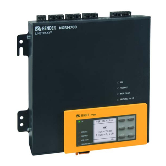
Bender NGRM700 Manual
Neutral grounding resistor monitor
Hide thumbs
Also See for NGRM700:
- Manual (80 pages) ,
- Quick start manual (9 pages) ,
- Quick start manual (8 pages)

Subscribe to Our Youtube Channel
Related Manuals for Bender NGRM700


Summary of Contents for Bender NGRM700
- Page 1 NGRM700 Neutral Grounding Resistor Monitor Manual EN NGRM700_D00292_04_M_XXEN/09.2019...
- Page 2 Bender GmbH & Co. KG Londorfer Str. 65 • 35305 Grünberg • Germany P.O. Box 1161 • 35301 Grünberg • Germany Tel.: +49 6401 807-0 • Fax: +49 6401 807-259 E-Mail: info@bender.de • www.bender.de © Bender GmbH & Co. KG All rights reserved.
-
Page 3: Table Of Contents
Table of Contents 1. Important information ................7 How to use this manual ................... 7 Technical support: service and support ............ 8 1.2.1 First level support ....................8 1.2.2 Repair service ...................... 8 1.2.3 Field service ......................8 Training courses ....................9 Delivery conditions ................... - Page 4 Table of Contents 4.2.2 Dimension diagram NGRM700 ..............18 Enclosure view ....................19 Removing FP200-NGRM from enclosure ..........19 Door mounting ....................20 Front cover for FP200-NGRM ..............20 5. Connection ..................... 21 Connection requirements ................21 Connection descriptions of CD-series coupling device ..... 22 Star connection ....................
- Page 5 Table of Contents History (menu 3) ....................42 Pulser (menu 4) ....................42 Display (menu 5) ....................43 HRG settings (menu 6) ................... 43 7.9.1 HRG system (menu 6.1) ................. 43 7.9.2 CT (menu 6.2) ....................43 7.9.3 NGR (menu 6.3) ....................44 7.9.4 Phase monitor (menu 6.4) ................
- Page 6 Table of Contents 12. Error codes ................... 67 13. Technical data ..................69 13.1 Tabular data ....................... 69 13.2 Ordering details ....................75 13.2.1 NGR monitor ...................... 75 13.2.2 Accessories ......................76 NGRM700_D00292_04_M_XXEN/09.2019...
-
Page 7: Important Information
This manual has been compiled with great care. It might nevertheless contain errors and mistakes. Bender cannot accept any liability for injury to persons or damage to property resulting from errors or mistakes in this manual. -
Page 8: Technical Support: Service And Support
Repairing, calibrating, testing and analysing Bender products Hardware and software update for Bender devices Delivery of replacement devices in the event of faulty or incorrectly delivered Bender devices Extended guarantee for Bender devices, which includes an in-house repair service or ... -
Page 9: Training Courses
ZVEI (Zentralverband Elektrotechnik- und Elektronikindustrie e. V.) (German Electri- cal and Electronic Manufacturer's Association) also applies. Sale and delivery conditions can be obtained from Bender in printed or electronic for- mat. 1.5 Inspection, transport and storage Inspect the dispatch and equipment packaging for damage, and compare the contents of the package with the delivery documents. -
Page 10: Disposal
13 August 2005 must be taken back by the manufacturer and disposed of properly. For more information on the disposal of Bender devices, refer to our homepage at www.bender-de.com -> Service & support. -
Page 11: Safety Instructions
The European standard EN 50110 can be used as a guide. 2.3 Intended use The NGRM700 is only intended for use in high-resistance grounded systems. In these systems, the NGRM700 monitors the current through the neutral-grounding resistor (NGR), ... -
Page 12: Glossary
Safety instructions Systems with a high-resistance grounded star point can be used when an interruption of the power supply would involve excessive costs due to production stoppage (e.g. automotive production, chemical industry). The ground fault that occurs between a phase and earth does not lead to a failure of the power supply in these systems. -
Page 13: Function
3. Function 3.1 Device features Determination of R with passive and active measurement methods Continuous monitoring of the R even if the installation is de-energised; Alarm or trip on ground fault Monitoring of the current I ... -
Page 14: Functional Description
In the case of the "auto" method, monitoring switches automatically between "active" and "passive" when the measured value exceeds or falls below the internal threshold. The threshold is 15 % of the nominal value and can be adjusted by Bender service if re- quired. -
Page 15: Recommended Minimum Value Rngr (Tripping Level 50 %)
Function 3.3 Recommended minimum value (tripping level 50 %) Temperature range –40…+70 °C, field calibration at 25 °C (Limited temperature range 0…+40 °C, field calibration at 25 °C) 3.3.1 Recommended for system voltage ≤ 4300 V CD1000/CD1000-2 CD1000-2 CD5000 400 V 600 V 690 V 1000 V... -
Page 16: Recommended Rngr For System Voltage Usys > 4300 V
Function 3.3.2 Recommended for system voltage > 4300 V CD14400 CD25000 6000 V 6600 V 7200 V 11000 V 14400 V 25000 V — — — — — — 693 Ω 762 Ω 831 Ω 1270 Ω 1663 Ω — 10 A 346 Ω... -
Page 17: Installation
Before installing and connecting the device, make sure that the installation has been de-energised. Observe the rules for working on electrical installations. 4.1 Screw mounting Fix the NGRM700 with four M4 screws (see dimension diagram NGRM700). 4.2 Dimension diagrams 4.2.1 Dimension diagram FP200-NGRM 135.5... -
Page 18: Dimension Diagram Ngrm700
Installation 4.2.2 Dimension diagram NGRM700 Mounting position 55.50 2.19 61.40 2.42 63.35 2.49 0.12 0.236 223.50 8.80 4.92 5.91 8.07 8.31 9.06 9.65 Fig. 4.2: Dimension diagram and mounting position NGRM700 NGRM700_D00292_04_M_XXEN/09.2019... -
Page 19: Enclosure View
Installation 4.3 Enclosure view A1 A2 11 12 14 21 22 24 31 32 34 NGRM700 ® LINETRAXX Front TRIPPED NGR FAULT GROUND FAULT FP200 MENU TEST RESET SERVICE < TRIPPED INFO DATA NGR FAULT GROUND FAULT R on/off Bottom... -
Page 20: Door Mounting
Installation 4.5 Door mounting *IP 65: 68+0.7/-0 mm 0.3 Nm ± 10 % Remote: max. 5 m MENU RESET TEST SERVICE < TRIPPED INFO DATA NGR FAULT GROUND FAULT RJ45: Switch Remote RJ45: Ethernet TRIPPED NGR FAULT GROUND FAULT Fig. 4.5: Door mounting 4.6 Front cover for FP200-NGRM B98060005 When installed in doors, the degree of protec-... -
Page 21: Connection
5. Connection 5.1 Connection requirements Only qualified personnel are permitted to carry out the work necessary to install, commission and run a device or system. Danger of electrocution due to electric shock! Touching live parts of the system carries the risk of: An electric shock ... -
Page 22: Connection Descriptions Of Cd-Series Coupling Device
5.2 Connection descriptions of CD-series coupling device Connection to star point G1, R Connection to R of the NGRM700 CD1000-2 CD1000 CD14400 G, E Connection to E of the NGRM700 CD5000 CD25000 and to the protective earth con- ductor of the installation (PE) NGRM700_D00292_04_M_XXEN/09.2019... -
Page 23: Star Connection
Connection 5.3 Star connection 5.3.1 Connection ≤ 690 V For these voltages, the phase monitor of the NGRM700 can be connected directly to the conductors to be monitored. Circuit breaker (for tripping systems) Ground 6 A 6 A 6 A... -
Page 24: Connection Usys ≤ 690 V With Pulser
50mA 21 22 24 31 32 34 11 12 14 L2 L3 AC/DC 24...240 V NGRM700 R s (G1) CD... FP200-NGRM E (G) Ethernet Pulser Fig. 5.2: Connection U ≤ 690 V with pulser The "N" connection of the CD-series coupling device should be as close to the transformer star point as possible. -
Page 25: Connection Usys > 690 V
Connection 5.3.3 Connection > 690 V For these voltages, the phase monitor of the NGRM700 can only be connected to the conductors to be monitored via potential transformers (PT). Circuit breaker (for tripping systems) PT * Ground Trip fault fault... -
Page 26: Artificial Neutral (Delta Connection)
11 12 14 21 22 24 31 32 34 50mA / 5A AC/DC 24...240 V CD... NGRM700 R s (G1) FP200-NGRM E (G) Ethernet Fig. 5.4: Artificial neutral with a zigzag transformer 5.4 Measuring current transformer connection Depending on the system to be monitored, a suitable measuring current transformer has to be chosen. - Page 27 W20…120 CTB31…41 W1-S35…W5-S210 W...AB W... Type Bender CT W...S... AN420 CT: Terminal k NGRM700: 50 mA NGRM700: 50 mA NGRM700: 5 A CT: Terminal l NGRM700: C NGRM700: C NGRM700: C Tab. 5.1: Selecting the right measuring current transformer NGRM700_D00292_04_M_XXEN/09.2019...
-
Page 28: Connection Of Relays (Ground-Fault, Ngr And Trip Relay)
Connection Measuring current transformer connection (W…AB) 50 mm 1.97 in WXS... W...AB 250 mm 9.84 in 50mA –12V +12V NGRM... CD... Fig. 5.5: Measuring current transformer connection W…AB When using a W…AB current transformer the arrow on the top of the CT must point to the right as shown in the wiring diagram (setting I >... -
Page 29: Connection To The X1 Interface
Connection 5.6 Connection to the X1 interface Pulser IN Reset IN Test IN Modbus RTU (A) Modbus RTU (B) Ground Analogue output Open Collector: Pulser OUT Open Collector: System condition (system health) Output for supply of external relays (+24 V, max. 100 mA) Tab. -
Page 30: X1: Output Q1
Connection 5.6.2 X1: Output Q1…2 Internal 24 V Connection to PLC +24 V, +24 V, max. 100 mA max. 100 mA Pull up Pull up 10 kΩ 10 kΩ max. 300 mA, 24 V FP200-NGRM FP200-NGRM External supply e.g.12...24 V +24 V, max. -
Page 31: X1: Analogue Output
Connection 5.6.3 X1: Analogue output Analogue output Mode Permissible load Current output 0…20 mA ≤ 600 Ω 4…20 mA ≤ 600 Ω 0…400 μA ≤ 4 kΩ Voltage output 0… 10 V ≥ 1 kΩ 2… 10 V ≥ 1 kΩ Either NGR current I or NGR resistance R can be assigned to the analogue out-... - Page 32 Connection NGRM700_D00292_04_M_XXEN/09.2019...
-
Page 33: User Interface Fp200-Ngrm
6. User interface FP200-NGRM FP200 MENU RESET TEST SERVICE < TRIPPED INFO DATA NGR FAULT GROUND FAULT Legend, FP200-NGRM No. Designation Description Display elements Operation LED, green; on when power supply is available The LC display shows device and measurement information. The LED is on when there is either a device fault or a connection SERVICE fault, and when the device is in maintenance mode. - Page 34 User interface FP200-NGRM No. Designation Description Device buttons Navigates up in a list or increases a value. MENU Opens the device menu. Cancels the current process or navigates one step back in the device menu. RESET Resets alarms. Navigates backwards (e.g. to the previous setting step) or selects <...
-
Page 35: Standard Display
User interface FP200-NGRM 6.1 Standard display FP200 MENU NGR Monitor RESET TEST NGR = 265Ω SERVICE I NGR = 0,01A TRIPPED INFO DATA NGR FAULT GROUND FAULT The pulse symbol in the lower part of the display indicates that the resistance of the R is actively measured. -
Page 36: Fault Indication (Inactive)
User interface FP200-NGRM 6.3 Fault indication (inactive) FP200 MENU UNGR(rms) Limit 269 V RESET TEST SERVICE 03.01.17 12:38 TRIPPED 03.01.17 12:38 DATA NGR FAULT GROUND FAULT An inactive fault is indicated on the display with a . If more than one fault has oc- curred, the number of faults is also indicated in the lower part of the display. -
Page 37: History Memory
User interface FP200-NGRM 6.5 History memory Up to 1023 alarm messages and device errors with date and time stamp can be stored in the history memory. If the maximum number of memory entries has been reached, the oldest entry will be overwritten by a new event record. Display the history memory at MENU >... - Page 38 User interface FP200-NGRM NGRM700_D00292_04_M_XXEN/09.2019...
-
Page 39: Menu
7. Menu 7.1 Overview , Method, R NGR rel sense, rms rel rms rel, fund 1. Data meas. values fund rel fund fund rel, harm harm rel harm harm rel, L1L2 L2L3 , f, U L3L1 1-E rms 2-E rms 3-E rms 2. -
Page 40: Navigating Through The Menu
Menu 7.2 Navigating through the menu Select a submenu using the buttons and press OK. Return from any submenu to the main menu by pressing ESC or < Return from any (sub)menu to the standard display by pressing and holding ESC for more than 2 s. 7.3 Changing settings Enter settings with text/numbers directly on the FP200-NGRM. -
Page 41: Harmonics (Menu 2)
L2L3 L3L1 Frequency System frequency Line-to-earth voltage RMS value Tempera- in the NGRM700 ture Tab. 7.1: Data measured values (menu 1) Note Relative measured values always indicate the ratio of the measured value to the nominal value. The selected harmonics are configured in the menu 6.5.11 and 6.5.12. -
Page 42: History (Menu 3)
Menu 7.6 History (menu 3) Alarm messages (since switching on the device or deleting the last history) are saved. History: Navigate through the list using the buttons. Delete: After confirming, the history is irreversibly deleted. 7.7 Pulser (menu 4) A ground fault can be located by means of a measuring clamp and the pulser function. The pulser relay is designed as Open Collector. -
Page 43: Display (Menu 5)
Menu 7.8 Display (menu 5) Choose whether the measured values for R and I should be displayed as absolute (in Ω or A) or relative (in % to the reference value). The relative value is the ratio of the measured value to the nominal value. 7.9 HRG settings (menu 6) 7.9.1 HRG system (menu 6.1) -
Page 44: Ngr (Menu 6.3)
Menu 7.9.3 NGR (menu 6.3) Menu Parameter Setting range Explanatory notes auto: automatic changeover between active and passive resistor monitoring 6.3.1 Method auto, passive passive: only passive resistor monitoring (see page Ratio of the potential transformer on the primary 6.3.2 PT primary 1…10.000 side PT second-... - Page 45 The number of restart attempts can be selected between 1 and 5. The NGRM700 remains in "Alarm stored" mode (menu 6.5.8) even after a shutdown. Response values For delay times, see also...
- Page 46 Menu Menu Parameter Setting range Explanatory notes NGR trip Time delay between NGR fault detection and On the shutdown by the trip relay. t is added to 6.5.5 0…60 s NGR trip device: the response time. t(NGRtrip) Ground fault: Trip relay switches after the time delay t has elapsed.
-
Page 47: System Settings (Menu 6.6)
Menu Menu Parameter Setting range Explanatory notes Upper limit 0…32 6.5.12 harmonic 0 = DC 1 = fundamental Indicate range of harmonic that should trigger 2 = 2 Harmon- the trip relay if the threshold value has been exceeded; only active when "Harmonics" is Lower limit …... - Page 48 Menu Setting Menu Parameter Explanatory notes range System OUT Fail-safe, (6.6.5.1) non-fail-safe Pulser OUT Fail-safe, (6.6.5.2) non-fail-safe Digital Active high: Activation of the 6.6.5 inputs/out- Pulser IN (6.6.5.3) function when input level puts Active high changes from "low" to "high" Active low Active low: Activation of the RESET IN (6.6.5.4)
-
Page 49: Field Calibration (Menu 6.7)
Menu 7.9.7 Field calibration (menu 6.7) During field calibration, all tolerances of the connected CD-series coupling device and the NGR are considered. The current measured value is calibrated to the set nominal value of the NGR (R NGR nom In order to achieve high accuracy, start the device and let it run for at least one hour in the operating environment before carrying out the field calibration. - Page 50 Decimal separators (7.4.2) Comma, point Password (7.5.1) Factory setting 0000 Password Status on, off Changes are discarded and reset to Factory settings factory settings Update via interface Software Update Service For Bender service only Tab. 7.8: Device settings overview (menu 7) NGRM700_D00292_04_M_XXEN/09.2019...
- Page 51 Set the time according to UTC (Coordinated Universal Time). For Germany, set +1 for wintertime (MEZ) and +2 for summer time (MESZ). Interface (menu 7.3) Set the parameters for connecting other communication devices to the NGRM700 in the interface menu: Write access (menu 7.3.1) Set whether the parameters of the device can be changed via Modbus or web server.
- Page 52 The used IP address is displayed in the Info menu (INFO button or menu 9). IP (menu 7.3.2.2) Set the appropriate IP address for the NGRM700. SN (menu 7.3.2.3) Set the appropriate subnet mask.
- Page 53 Menu TTL for subscription (menu 7.3.3.5) Set a time between 1 s…1092 min. This time determines in what intervals the NGRM700 sends mes- sages to e.g. a gateway. Severe alarms are always sent immediately. Modbus TCP (menu 7.3.4) Settings for communication with other devices via Modbus TCP.
-
Page 54: Commissioning (Menu 8)
50 mA or 5 A Field calibration (8.12) Start or do not start 7.12Info (menu 9) The NGRM700's current settings can be viewed in the Info menu. Navigate through the different views using the arrow buttons: Device name, serial number, article number... -
Page 55: Initial Commissioning
8. Initial commissioning The following parameters must be entered for initial commissioning: System voltage U (phase-to-phase) The corresponding coupling device must be used depending on the system voltage: for U ≤ 4.3 kV: CD1000, CD1000-2, CD5000 (20 kΩ) for U >... -
Page 56: Output Relays Operating Modes
Initial commissioning Resistance trip threshold ( Both trip thresholds for the resistance are set as a percentage of the nominal NGR. Setting range of trip threshold R 10…90 % (factory setting 50 %) 110…200 % (factory setting 200 %). In the case of the passive measurement method the resistance R is determined us- ing the current and voltage measurements. - Page 57 Initial commissioning Max. Coupling Ground-fault trip settings trip device (menu 6.5.6) (Menu 6.5.7) CD1000 400…690 V 24 h on or off CD1000-2 CD1000 300 s 691…1000 V CD1000-2 24 h on or off CD5000 1001…4300 V CD5000 24 h on or off CD14400 4301…14550 V 60 s...
- Page 58 Initial commissioning Ground-fault relay timing diagram Ground fault Ground fault Ground fault relay Trip relay 40 ms = 100 ms...24 h,∞ GF trip Fig. 8.1: Ground-fault relay timing diagram NGR relay timing diagram NGR fault NGR fault NGR fault relay Trip relay <...
-
Page 59: Rms Trip Signal, Fundamental, Harmonics
Initial commissioning 8.3 RMS trip signal, fundamental, harmonics Which measured value causes tripping can be selected via the "Trip signal" parameter (menu 6.5.10). Trip signal can be: The RMS value of current or voltage over the entire frequency range (up to approx. 3.8 kHz). - Page 60 Initial commissioning NGRM700_D00292_04_M_XXEN/09.2019...
-
Page 61: Analogue And Digital I/O Configuration
9. Analogue and digital I/O configuration 9.1 Analogue output (menu 6.6.4) Either NGR current I or NGR resistance R can be assigned to the analogue out- put. A voltage or current signal proportional to the measured value is applied to the output. -
Page 62: Use Of Q1: System Condition
Analogue and digital I/O configuration 9.2.1 Use of Q1: System condition No system Intern. 24 V System error Mode error +24 V, detected detected max. 100 mA Pull up Fail-safe energised de-energised 10 kΩ Q1 low Q1 high 24 V, max. -
Page 63: Test Cycle
10. Test cycle Since the relays are not monitored in the hardware or software, the relays must be test- ed at regular intervals to verify proper functioning. The frequency of the test cycle is subject to the safety requirements of the operator but it must be carried out at least every six months. - Page 64 Test cycle NGRM700_D00292_04_M_XXEN/09.2019...
-
Page 65: Factory Settings
11. Factory settings Menu Factory settings Menu 6.1: HRG system 1. U 400 V sys (L-L) 2. CD-NGRM CD1000 3. Frequency 50 Hz 4. I NGR nom 5. R 470 Ω NGR nom Menu 6.2: CT 1. CT primary 2. CT secondary 3. - Page 66 Factory settings Menu Factory settings 6. Ground-fault trip 7. t GF trip 8. Alarm stored 9. t restart 10. Restart count 11. Trip signal 12. Upper limit harmonic 13. Lower limit harmonic Menu 6.6: System settings Mode fail-safe 1. Ground-fault relay Rel.
-
Page 67: Error Codes
12. Error codes Error code/ Description/Cause Action Service code Restart field calibration. If the error 6.10 Error during field calibration persists, contact service. The installation must operate error- Field calibration could not be free before starting a field calibration. 6.11 started Restart field calibration. - Page 68 Error codes NGRM700_D00292_04_M_XXEN/09.2019...
-
Page 69: Technical Data
13. Technical data 13.1 Tabular data Insulation coordination according to IEC 60664-1/IEC 60664-3/DIN EN 50178 Definitions Measuring circuit 1 (IC1) ............................(L1, L2, L3) Supply circuit (IC2) ................................. (A1, A2) Measuring circuit/Control circuit (IC3)....................(RS, E, CT), (X1, Ethernet) Output circuit 1 (IC4) ..............................(11, 12, 14) Output circuit 2 (IC5) ..............................(21, 22, 24) Output circuit 3 (IC6) ..............................(31, 32, 34) Rated voltage ..................................690 V... - Page 70 Technical data Voltage tests (routine test) acc. to IEC 61010-1 IC2 / (IC3…6)................................AC 2.2 kV IC3 / (IC4…6)................................AC 2.2 kV IC4 / (IC5…6)................................AC 2.2 kV IC5 / (IC6)..................................AC 2.2 kV Supply voltage Nominal supply voltage U ≤ 2000 m ............................AC/DC, 24…240 V ≤...
- Page 71 Technical data Monitoring Measuring input R ..............................< 33 V RMS Measuring range NGR (with R = 20 kΩ) active ......................0…10 kΩ Measurement uncertainty for T = 0…+40 °C....................±20 Ω Measurement uncertainty for T = –40…+70 °C................... ±40 Ω Measuring range NGR (with R = 100 kΩ) active......................0…10 kΩ...
- Page 72 Technical data Coupling for U ≤ 4.3 kV ......................CD1000, CD1000-2, CD5000 (20 kΩ) for U > 4.3 kV ........................CD14400, CD25000 (100 kΩ) Monitoring with R = 20 kΩ ............DC / 50/60 Hz / 50…3200 Hz; (400/√3) … ≤ (4300/√3) V with R = 100 kΩ...
- Page 73 Technical data Analogue output (M+) Operating mode.................................. Linear Functions..................................I Current................0…20 mA (≤ 600 Ω), 4…20 mA (≤ 600 Ω), 0…400 μA (≤ 4 kΩ) Voltage..........................0…10 V (≥ 1 kΩ), 2…10 V (≥ 1 kΩ) Tolerance related to the current/voltage end value......................±20 % Ground-fault, NGR, trip relay Switching elements............................
- Page 74 Technical data Connection Screw-type terminals Tightening torque......................0.5…0.6 Nm (5…7 lb-in) Conductor sizes ............................AWG 24-12 Stripping length..............................7 mm rigid/flexible ............................0.2…2.5 mm² flexible with ferrule with/without plastic sleeve ................0.25…2.5 mm² Multiple conductor, rigid......................... 0.2…1 mm² Multiple conductor flexible ......................... 0.2…1.5 mm² Multiple conductor flexible with ferrule without plastic sleeve ............
-
Page 75: Ordering Details
13.2.1 NGR monitor Supply voltage/Frequency range Type Art. No. AC 24…240 V, 40…70 Hz NGRM700 B94013700 DC 24…240 V Accessory for FP200-NGRM: B98060005 Transparent front cover 144x72 (for IP65)* *When using the "transparent front cover 144x72 (IP 65)" the cutout in the switchboard cabinet must be extended in height from 66 mm to 68 mm (+0.7/-0 mm). -
Page 76: Accessories
Technical data 13.2.2 Accessories CD-series coupling device Voltage Type Art. No. 400…690 V CD1000 B98039010 400…1000 V CD1000-2 B98039053 1000…4200 V CD5000 B98039011 4300…14550 V CD14400 B98039054 14551…25000 V CD25000 B98039055 Measuring current transformer Voltage/Current Type Art. No. AC up to 10 A B98080003 B98080010 B98080018... - Page 77 INDEX Acknowledging a fault message 36 Enclosure view 19 Alarm 54 Error codes 67 Analogue output 61 Ethernet 52 BCOM 52 Factory settings 65 Fault indication 35 Field calibration 49 FP200-NGRM 19 CEST (Central European Summer Time) 51 Connection - Measuring current transformer 26 - relay 28 Glossary 12 - Usys >...
- Page 78 INDEX Menu 4 42 - Usys ≤ 690 V 23 Menu 5 43 Subsystem 52 Menu 6 43 Support 8 Menu 7 49 Menu 8 54 Menu 9 54 Technical data 69 Modbus TCP 53 Test cycle 63 Timing diagram - Ground-fault relay 58 NTP 51 - NGR relay 58...
- Page 80 Bender GmbH & Co. KG Londorfer Str. 65 • 35305 Grünberg • Germany P.O. Box 1161 • 35301 Grünberg • Germany Tel.: +49 6401 807-0 • Fax: +49 6401 807-259 E-Mail: info@bender.de • www.bender.de © Bender GmbH & Co. KG All rights reserved.
Need help?
Do you have a question about the NGRM700 and is the answer not in the manual?
Questions and answers