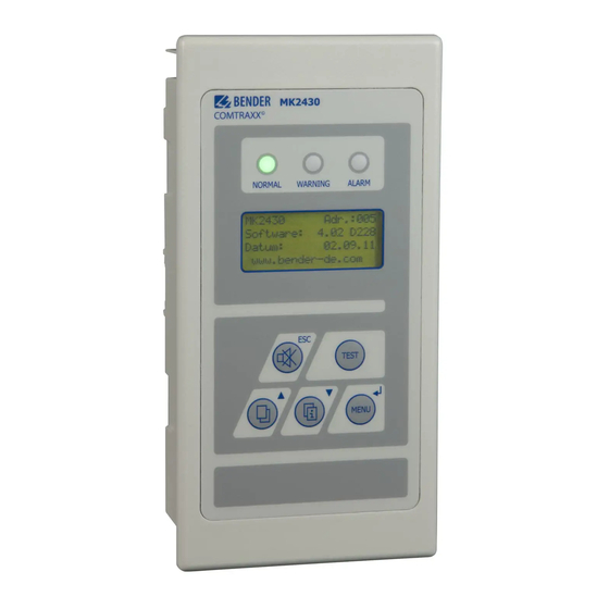
Bender COMTRAXX MK2430 Manual
Alarm indicator and test combination
Hide thumbs
Also See for COMTRAXX MK2430:
- Quick start (4 pages) ,
- Manual (84 pages) ,
- Quick start manual (8 pages)

Subscribe to Our Youtube Channel
Related Manuals for Bender COMTRAXX MK2430


Summary of Contents for Bender COMTRAXX MK2430
- Page 1 Manual COMTRAXX® MK2430 Alarm indicator and test combination Software version: 4.1x MK2430_D00129_02_M_XXEN/09.2019...
- Page 2 Bender GmbH & Co. KG P.O. Box 1161 • 35301 Grünberg • Germany Londorfer Str. 65 • 35305 Grünberg • Germany Tel.: +49 6401 807-0 • Fax: +49 6401 807-259 E-mail: info@bender.de • www.bender.de © Bender GmbH & Co. KG All rights reserved.
-
Page 3: Table Of Contents
Table of Contents 1. Important information ................7 How to use this manual ................... 7 Technical support: service and support ............ 8 1.2.1 First level support ....................8 1.2.2 Repair service ...................... 8 1.2.3 Field service ......................8 Training courses ....................9 Delivery conditions ................... - Page 4 Table of Contents 3.4.4.1 BMS bus ......................19 3.4.4.2 USB interface ....................19 4. Installation and connection ..............21 Safety instructions ................... 21 Installing the device ..................22 4.2.1 Overview of enclosure variants ..............22 4.2.2 Dimension diagram flush-mounting enclosure ........22 4.2.2.1 Flush-mounting ....................
- Page 5 Table of Contents 6. Troubleshooting ................... 45 MK2430 error messages ................45 Malfunctions ...................... 46 7. Operation ....................47 Operator control and display elements ..........47 Quick-start guide ..................... 49 7.2.1 Display in fault-free operating condition ..........49 7.2.2 Display in fault condition ................49 7.2.3 Test function .....................
- Page 6 Table of Contents 8.4.4.2 Control menu 2: Reset (AlarmClear) ............70 8.4.4.3 Control menu 3: EDS Start/Stop ............... 71 8.4.4.4 Control menu 4: Test communication (MK2430-11 only) ....71 8.4.5 Menu 5: External devices ................72 8.4.6 Menu 6: Info ....................... 73 Overview of setting options ................
-
Page 7: Important Information
Although great care has been taken in the drafting of this operating manual, .it may nevertheless contain errors and mistakes. Bender cannot accept any liability for injury to persons or damage to property resulting from errors or mistakes in this manual. -
Page 8: Technical Support: Service And Support
Repair, calibration, testing and analysing Bender products Hardware and software update for Bender devices Delivery of replacement devices for faulty or incorrectly delivered Bender devices Extended warranty for Bender devices with in-house repair service resp. replace- ... -
Page 9: Training Courses
ZVEI (Zentralverband Elektrotechnik- und Elektronikindustrie e.V., (German Elec- trical and Electronic Manufacturers' Association) also applies. Conditions of sale and delivery can be obtained from Bender in printed or electronic for- mat. 1.5 Inspection, transport and storage Inspect the packaging and equipment packaging for damage, and compare the con- tents of the package with the delivery documents. -
Page 10: Disposal
13th August 2005 must be taken back by the manufacturer and disposed of properly. For more information on the disposal of Bender devices, refer to our website at www.bender-de.com -> Service & support. -
Page 11: Safety Instructions
Bender devices are built in accordance with state-of-the-art technology and accepted recognised safety regulations. However, the use of such devices may introduce risks to the life and limb of the user or third parties and/or result in damage to the Bender devices and other property. -
Page 12: Intended Use
2.3 Intended use The universal MK2430 alarm indicator and test combination is used for visual and acoustic indication of operating status and alarm messages from Bender's EDS, RCMS, ATICS® and MEDICS® systems. In MEDICS® monitoring systems, the MK2430 meets the requirements of IEC 60364-7-710:2002-11 and DIN VDE 0100-710:2002-11 with regard to test functions for IT system monitoring and alarms from changeover devices. - Page 13 Safety instructions The clear text display makes information easy to understand. The connection between the MK… and the transfer switching and monitoring modules is implemented with bus technology. During normal operation, the MK2430 indicates the readiness for operation of the system. Version MK2430-11 features 12 digital inputs allowing messages from other technical equipment to be recorded and displayed on the MK2430, for example from medical gases or battery-supported safety power supply systems (BSV systems).
- Page 14 Safety instructions MK2430_D00129_02_M_XXEN/09.2019...
-
Page 15: System Description
3. System description 3.1 MEDICS® The MK2430 alarm indicator and test combinations are integral components of the MEDICS® system. MEDICS® is an intelligent system that guarantees safe power supply in medical locations. Example of a section of a hospital where a MEDICS® system is installed: UMA710... -
Page 16: Characteristics
System description Legend of the example MK2430 Alarm indicator and test combination RCMS… Residual current monitoring systems for TN-S systems SMI472 Signal converter for third-party systems (e.g. med. gases, BSV sys- tems) TM… Alarm indicator and operator panel UFA107E… Changeover and monitoring module for IT systems with an EDS…insulation fault location system UMA107E…... - Page 17 System description time there is an acoustic signal (acknowledgeable/can be muted). If a second message is received while the first is still pending, the acoustic signal will sound again and the messages appear alternately on the LC display. The address of the device triggering the alarm can also be requested.
-
Page 18: Function
System description 3.3 Function 3.3.1 Display/operating elements The backlit display features four lines of 20 characters each. It supplies medical and technical personnel with clear and unambiguous information to help them make decisions. Every alarm message comprises three lines which appear spontaneously and three additional lines which can be displayed at the touch of a button. -
Page 19: Versions
3.4 Versions 3.4.1 MK2430-12 The MK2430-12 is used for visual and acoustic indication of alarms from Bender's EDS, RCMS and MEDICS systems® and for testing assigned devices (e.g. insulation monitoring devices, LIM, GFCI). Furthermore, the MK2430-12 can be used as parallel indication in conjunction with MK2430-11 and SMI472-12. - Page 20 System description Programming and reading the MK2430 Connect the MK2430 to a PC: directly via the USB interface or via an RS-232/RS-485 converter DI-2 or a USB/RS-485 converter DI-2USB to the BMS bus. You can use the optional TMK-SET PC software to display and change the MK2430 set- tings.
-
Page 21: Installation And Connection
4. Installation and connection 4.1 Safety instructions Only qualified personnel are permitted to carry out the work necessary to install, commission and run a device or system. Risk of fatal injury due to electric shock! Touching live parts of the system carries the risk of: An electric shock DANGER ... -
Page 22: Installing The Device
Installation and connection 4.2 Installing the device 4.2.1 Overview of enclosure variants – The MK2430 is installed in a flush-mounting enclosure. With a special mount- ing kit it is also suitable for installation in a panel or cavity wall. – MK2430A in surface-mounting enclosure 4.2.2 Dimension diagram flush-mounting enclosure Fig. -
Page 23: Flush-Mounting
Installation and connection 4.2.2.1 Flush-mounting The flush-mounting enclosure is already included in the scope of delivery of the MK2430. 1. Insert the cardboard that has been supplied into the flush-mounting enclo- sure to provide protection against pollution. 2. Insert the enclosure so that it is flush with the wall surface. The flush-mounting enclosure must not be installed lopsidedly or warped, and must not be installed too deep below the surface. -
Page 24: Cavity Wall And Panel Mounting
Installation and connection 4.2.2.2 Cavity wall and panel mounting For cavity wall or panel mounting you will need a "Complete mounting kit" (Art. No. B95101000). Panel mounting Cavity wall mounting 4.2.2.3 Mounting brackets By means of the mounting brackets (attached on each side) the MK2430 snaps into the flush-mounting enclosure. -
Page 25: Dimension Diagram Surface-Mounting Enclosure
Installation and connection Screw mounting The MK2430S-11, MK2430S-12 and MK2430H-12 versions are designed for screw mounting. MK2430H-12 is mounted horizontally. When screw mounting, make sure that the front panel does not bend! 4.2.3 Dimension diagram surface-mounting enclosure MK2430A MK2430 Fig. 4.2: MK2430 in surface-mounting enclosure 4.2.3.1 Installation of the surface-mounting enclosure A smooth and even surface is a precondition for installation. -
Page 26: Connecting The Device
Installation and connection 4.3 Connecting the device 4.3.1 Safety instructions Danger of electric shock! Follow the basic safety rules when working with electricity. Observe the information on rated voltage and supply voltage specified in the DANGER technical data! Connect the MK2430 exclusively according to the wiring diagram in this chapter. -
Page 27: Wiring Diagram
Installation and connection 4.3.3 Wiring diagram MK2430_D00129_02_M_XXEN/09.2019... - Page 28 DIP switch on the MK2430 and alarm indicator and opera- tor panel). BMS bus connection: Various Bender devices with a BMS bus interface, such as insulation monitoring devices isoMED427P, 107TD47, control devices PRC487, residual current moni- tors RCMS470, can be connected to the BMS bus.
-
Page 29: Connection Assignment
Installation and connection 4.3.4 Connection assignment The connections are located on the back of the device. 4.3.4.1 MK2430-12 The MK2430-12 features only one terminal strip as it receives all messages via the BMS bus. These messages can be received from an isoMED427P, 107TD47, an MK2430-11, a signal converter SMI47x, an EDS…... -
Page 30: Mk2430-11
Installation and connection 4.3.4.2 MK2430-11 The MK2430-11 alarm indicator and test combination provides additional terminal strips for the 12 digital inputs and one optional relay output. IN1…IN12 Digital inputs 1…12 0 (IN1…4) Common connection "0" for digital inputs 1…4 0 (IN5…8) Common connection "0"... - Page 31 Installation and connection Example 1: Operating theatre or intensive care unit with two IT systems and three rooms Device Parameter Address settings First UMC107E changeover and monitoring module 107TD47 Bus address PRC487 Bus address Second UMC107E changeover and monitoring module 107TD47 Bus address PRC487...
- Page 32 Installation and connection Example 2: Intensive care unit with two IT systems and four rooms Device Parameter Address settings First UFC107E changeover and monitoring module 107TD47 Bus address PRC487 Bus address PGH474 Bus address EDS474-12 Bus address Second UFC107E changeover and monitoring module 107TD47 Bus address PRC487...
- Page 33 Installation and connection Device Parameter Address settings Bus address Third Test address 3, 5 MK2430… Alarm address 1, 2, 3, 4, 5, 6, 8, 61, 62, 111, 112 Bus address Fourth Test address 3, 5 MK2430… Alarm address 1, 2, 3, 4, 5, 6, 7, 61, 62, 111, 112 MK2430_D00129_02_M_XXEN/09.2019...
- Page 34 Installation and connection Example 3: Intensive care unit with two IT systems and four rooms „B“ „A“ ATICS ATICS EDS151 EDS151 Device Parameter Address settings First changeover and monitoring module ATICS "A" Bus address EDS151 "A" Bus address Second changeover and monitoring module ATICS "B"...
- Page 35 Installation and connection Example 4: System with 3 RCMS, one MK2430 and one MK800 Device Parameter Address settings Residual current monitors 1. RCMS460 Bus address 2. RCMS460 Bus address 3. RCMS460 Bus address Alarm indicator and test combinations Bus address MK2430…...
- Page 36 Installation and connection MK2430_D00129_02_M_XXEN/09.2019...
-
Page 37: Commissioning And Testing
5. Commissioning and testing The following flow chart explains the commissioning process: 1. Tests before switching on 2. Tests after switching on 3. Parameter setting – Settings on the MK2430 – Settings using the software TMK-SET 4. Tests after parameter setting Please write down all settings and keep them with the equipment or instal- lation documentation. -
Page 38: Tests Before Switching On
Commissioning and testing 5.1 Tests before switching on Does the MK2430 use the Provide the appropriate correct supply voltage operating voltage. (see device nameplate)? Is the supply voltage Connect the supply properly connected? voltage properly. Connect the BMS bus Is the BMS bus properly properly and check connected? polarity of the terminals... -
Page 39: Tests After Switching On
Commissioning and testing 5.2 Tests after switching on 5.3 Parameter setting All settings can be carried out via the TMK-SET software. Alternatively, the basic settings can be carried out via the MK2430 menu (see diagrams). MK2430_D00129_02_M_XXEN/09.2019... -
Page 40: Settings On The Mk2430
Commissioning and testing 5.3.1 Settings on the MK2430 MK2430_D00129_02_M_XXEN/09.2019... -
Page 41: Settings Using The Tmk-Set Software
Commissioning and testing 5.3.2 Settings using the TMK-SET software MK2430_D00129_02_M_XXEN/09.2019... -
Page 42: Tests After Parameter Setting
5.3.3 Tests after parameter setting 5.4 Periodic verification and service 5.4.1 Periodic verification The following periodic verification must be performed on electrical installations in compliance with the local or national regulations that apply. For your Bender products, we recommend: MK2430_D00129_02_M_XXEN/09.2019... - Page 43 Checking the setting values and changeover periods. skilled months person Test the changeover device, the IT system monitoring, and the con- Bender Every 24 nection to the SCADA system (Supervisory Control and Data Acqui- months sition) (if applicable) as well as the interaction between the components in the system.
-
Page 44: Maintenance
Commissioning and testing 5.4.2 Maintenance MK2430 does not contain any parts that require maintenance. Despite this, the intervals specified for periodic verification should be adhered to. 5.4.3 Cleaning and disinfection The front foil is glued in ensuring marginal fit. The device is mounted without using screws (all versions except MK2430S). -
Page 45: Troubleshooting
Overflow ERROR (11) Stack Error Write down the error code and contact the Bender service. Checksum ERROR Program memory defective Replace the MK2430* Please write down the cause of error, the error number and if applicable the error code. -
Page 46: Malfunctions
Troubleshooting 6.2 Malfunctions List of possible errors and proposals for the correction of the faults. This error list does not claim to be exhaustive. Possible error codes occurring during a test are listed in the chapter "Test function" on page 51f. Error Possible cause/Actions MK2430 display blank. -
Page 47: Operation
7. Operation This chapter can also be used as a quick-start guide by technical operating personnel. 7.1 Operator control and display elements LED and LCD "NORMAL" LED: Power On indicator, green (is only lit when no warnings or alarms are pending) "WARNING"... - Page 48 Operation The buttons have the following functions: In operating mode In menu mode "ESC" button; Exit function (without saving) " " button (mute button); or go up one menu level. Set buzzer to mute after an alarm/ When the buzzer is activated, the ESC acknowledge alarm.
-
Page 49: Quick-Start Guide
Operation 7.2 Quick-start guide The illustrations below serve as examples. 7.2.1 Display in fault-free operating condition There are no warnings or alarms pending. The green "Normal" LED is lit. The LC display shows the programmed standard display. A maximum of 3 measured values can be displayed in lines 1…3. - Page 50 Operation – Line 4 Status line = Consecutive number of message displayed = Number of pending messages = Message text page, in this case page 1 = Insulation fault location or test in progress (refer to table) 09:50 = Time (example) Possible displays during insulation fault location or testing: Meaning EDSa...
-
Page 51: Test Function
Operation The display may deviate depending on user-defined messages. If messages are pending and one of the arrow buttons is pressed, the latest message will appear on the display. If no further button is pressed, this message will be displayed for 15 seconds. 7.2.3 Test function Press and hold down the "TEST"... - Page 52 Operation The following error codes are displayed in the event of an ISOMETER® failing the test: Meaning for hospital Error Meaning for industrial ISOMETER®s (e.g. 107TD47, Note code ISOMETER®s (e.g. IRDH…) isoMED427P, ATICS …) No messages received from the No messages received from the ISOMETER®...
-
Page 53: Menu Mode: Operation And Setting
Software 4.02 D228 Date: 02.05.12 www.bender.de If the MK2430 has not been turned on for several days, a longer time may be required for start-up (approx. 30 seconds). In this case, enter the time and date again. If there are no messages pending, the standard display will be shown when the starting procedure is completed. - Page 54 Menu mode: Operation and setting To open the main menu, press and hold the "Menu" button for approx. two seconds. 1.Exit 2.History 3.Settings 4. Control 6.External devices 7.Info In the main menu, use the following buttons: Exit function or go up one menu level ▲, ▼...
-
Page 55: Menu Overview Diagram
Menu mode: Operation and setting 8.2 Menu overview diagram The following diagram will help you to navigate through the menus: 1.Exit 2.History 3.Settings 1.Exit 2.Alarm addresses 3.Test addresses 4.Digital inputs 5.Buzzer 6.Common reset 7.Clock 8.Language 9.Interface 10.Relay 11.Password 12.Service menu 4.Control 1.Exit 2.Reset (AlarmClear) -
Page 56: Main Menu Functions
Menu mode: Operation and setting 8.3 Main menu functions Menu item Function Page 1. Exit Exit menu mode Displays the history memory with information about mes- 2. History sages, acknowledgements and their timestamps. 3. Settings Various settings for this MK2430 4. -
Page 57: Menu 2: History
Menu mode: Operation and setting 8.4.2 Menu 2: History The MK2430 can store up to 250 messages in the history memory (ring buffer). If more than 250 messages are stored by the MK2430, message 251 will overwrite entry 1. The "History" menu provides information about messages, acknowledgements and their timestamps. -
Page 58: Menu 3: Settings
Menu mode: Operation and setting Possible displays in the last line of the history memory message text display: Text Meaning Address: Address of the device triggering the message (aaa= device address, kk= aaa/kk channel no. of the message). Digital In Number (kk) of the digital input on this MK which triggered the message. -
Page 59: Exit
(alarm relay) on the MK2430-11. 11. Password Changing the password, enabling/disabling the password. These settings can only be made by authorised Bender serv- ice personnel. Retrieve information about the device status, 12. Service menu make settings for special operating conditions and execute firmware update. -
Page 60: Settings Menu 2: Alarm Addresses
Menu mode: Operation and setting 8.4.3.2 Settings menu 2: Alarm addresses Setting the bus addresses for devices the alarm messages of which are to be displayed on this MK2430. The address of this MK2430 is automatically set to "On". All other alarm addresses are set to: "Off". -
Page 61: Settings Menu 3: Test Addresses
Menu mode: Operation and setting Possible system number settings: Meaning There is no text in line 1 of the alarm message. 01…04 Texts of "System 01" to "System 04" are displayed. Programmed text is displayed. 8.4.3.3 Settings menu 3: Test addresses Set the bus addresses for insulation monitoring devices (e.g. -
Page 62: Settings Menu 4: Digital Inputs (Mk2430-11 Only)
Menu mode: Operation and setting 8.4.3.4 Settings menu 4: Digital inputs (MK2430-11 only) Setting the operating behaviour for digital inputs IN01…IN12. The following setting can be made individually for each input: "24V" (high) or "0V" (low). For inputs set to "24V", an alarm message is sent when 24 V are applied. If "0V" is set for an input, an alarm message will be sent when the voltage detected is 0 V. - Page 63 Menu mode: Operation and setting Specific alarm messages These messages contain details about medical gases and BSV systems. Alarm messages for medical gases are signalled by the red "ALARM" LED and the sound of the buzzer. The buzzer can be set to mute (acknowl- edged).
-
Page 64: Settings Menu 5: Buzzer
Menu mode: Operation and setting 8.4.3.5 Settings menu 5: Buzzer The buzzer will sound in the event of a warning or an alarm message. Setting of the audio frequency and repetition rate to distinguish both buzzer sounds. 1.Exit 2.Warning: 3.Alarm: 1. -
Page 65: Settings Menu 7: Clock
Menu mode: Operation and setting 8.4.3.7 Settings menu 7: Clock This menu is used to set the time, the date and the date format. These settings remain stored for approx. 5 days following a power supply failure. The clock switches automatically to Central European summertime (CEST) and wintertime (CET). -
Page 66: Settings Menu 8: Language
Menu mode: Operation and setting 8.4.3.8 Settings menu 8: Language Selection of the language for menu operation and message display (alarm and operating messages) of the MK2430. Changes will be effective immediately. 1.Exit 2.Menu: English 3.Messg.: English 1. Exit Back to the main menu. 2. -
Page 67: Settings Menu 9: Interface
Menu mode: Operation and setting 8.4.3.9 Settings menu 9: Interface Sets the actual device address and indicates the transmission rate (baud rate) for the connection to the internal BMS bus (RS-485). 1.Exit 2.Addr. RS485: 3.Baud RS485: 09600 1. Exit Back to the main menu. 2. -
Page 68: Settings Menu 10: Relay
Menu mode: Operation and setting 8.4.3.10 Settings menu 10: Relay Set the operating mode and function for the optional alarm relay of the alarm indicator and test combination. This menu only exists for MK2430..-11. 1.Exit 2.Relay mode: 3.Function: Device error 1. -
Page 69: Settings Menu 11: Password
(except the service menu) until menu mode is exited. 8.4.3.12 Settings menu 12: Service menu Only authorised Bender service staff is allowed to make settings in this menu. This menu is only accessible after entering a master password. In the service menu, information about the device status can be called up and settings for specific operating conditions can be made. -
Page 70: Menu 4: Control
Menu mode: Operation and setting 8.4.4 Menu 4: Control This menu offers various options for controlling individual devices or the whole system: Menu item Function Page 1. Exit Exit "Control" menu; go up one menu level. 2. Reset Resetting all fault messages pending on the BMS bus. (AlarmClear) 3. -
Page 71: Control Menu 3: Eds Start/Stop
Menu mode: Operation and setting 8.4.4.3 Control menu 3: EDS Start/Stop Press "↵" to manually start and stop the EDS system test procedure. This function can only be activated for the master. The current status appears in the last line. 1.Exit 1.Exit 2.Reset (AlarmClear) -
Page 72: Menu 5: External Devices
Menu mode: Operation and setting 8.4.5 Menu 5: External devices This menu is used to set and control external devices. Functions include for example displaying information about connected devices (address, software version, device type) or continuous displaying of a channel on a connected monitor. All devices connected to the BMS bus are indicated. -
Page 73: Menu 6: Info
Software 4.02 D228 Date: 02.09.11 www.bender.de Information about the device type, the version and the last time the assignments were transmitted. Assignments are settings carried out via the PC software TMK-SET: Enter standard texts Assign texts and functions to the alarm messages and digital inputs of the ... - Page 74 Menu mode: Operation and setting MK2430_D00129_02_M_XXEN/09.2019...
-
Page 75: Technical Data
9. Technical data 9.1 Technical data Insulation coordination acc. to IEC 60664-1 Rated insulation voltage.......................AC 250 V Rated impulse voltage/pollution degree ..................4 kV/3 Supply voltage Supply voltage ........................AC/DC 24 V Frequency range .......................0/40…60 Hz Operating range ..................AC 18…28/DC 18…30 V Power consumption ........................ - Page 76 Technical data Inputs (MK2430…-11 only) Digital inputs........................12 (IN1…IN12) Galvanic separation ..........................yes Activation of the digital inputs........via potential-free contacts/extraneous voltage Operating principle........N/O or N/C operation individually selectable for each input Factory setting ........................N/O operation Voltage range (high) .....................AC/DC 10…30 V Voltage range (low) ......................
- Page 77 Technical data Colours Front foil................RAL 7035 (light grey); RAL 7040 (basalt grey) Marking......................RAL 5005 (ultramarine blue) Front plate ....................... RAL 7035 (light grey) Switching elements (MK2430…-11 only) Number ........................1 changeover contact Function ..........................programmable Operating principle ..............N/C or N/O operation (programmable) Electrical endurance under rated operating conditions, number of cycles........
-
Page 78: Standards, Approvals And Certifications
Technical data Connection properties (inputs) Connection of single conductors: rigid/flexible/conductor sizes ..........0.08…1.5/0.08…1.5 mm /AWG 28-16 flexible with ferrules, without/with plastic sleeve* ........0.25…1.5/0.25…0.5 mm Multi-conductor connection (2 conductors with the same cross section): rigid/flexible ..................... 0.08…0.5/0.08…0.75 mm flexible with ferrule without plastic sleeve..............0.25…0.34 mm flexible with TWIN ferrule with plastic sleeve ................0.5 mm Stripping length.......................... -
Page 79: Ordering Details
Technical data 9.2 Ordering details Type Description Art. No. MK2430-11 Alarm indicator and test combination according to IEC B 9510 0001 60364-7-710:2002-11/DIN VDE 0100-710, featuring a BMS bus and a USB interface, 12 digital inputs, one relay output, alarm texts programmable via interfaces and PC, standard text display. - Page 80 Technical data Type Description Art. No. Parameterisa- - TMK-SET V 4.x parameterisation software for as Internet tion software MK2430, MK800, TM800 download - TMK-HISTORY V 3.x for MK2430, MK800, TM800, TM1000 and PRC1470 - USB driver software for MK2430, MK800 and TM800 - MEDISET V1.x parameterisation software for TM1000 and PRC1470 MK2430_D00129_02_M_XXEN/09.2019...
-
Page 81: Index
Automatic mode 71 Firmware version 53 Baud rate 67 Flush-mounting enclosure 23 Beep c 45 Functional test 43 Bender service personnel 69 BMS bus 19 Buzzer 49 History memory 18 How to use this manual 7 Cable length 26 Cavity wall mounting 24... - Page 82 INDEX - gases 63 Medical gases 63 Safety instructions 26 MEDICS® 15 Selective operation 11 MK2430-11 19 Service 8 MK2430-12 19 Setting 58 MK2430C-… 19 Setting options 73 Monitor 72 Setting values 43 Mounting brackets 24 Single mode 71 Snap-on mounting 24 Software 18 Standard display 53 National languages 18...
- Page 84 Bender GmbH & Co. KG P.O. Box 1161 • 35301 Grünberg • Germany Londorfer Str. 65 • 35305 Grünberg • Germany Tel.: +49 6401 807-0 • Fax: +49 6401 807-259 E-mail: info@bender.de • www.bender.de © Bender GmbH & Co. KG All rights reserved.
Need help?
Do you have a question about the COMTRAXX MK2430 and is the answer not in the manual?
Questions and answers