
Related Manuals for Bender NGRM500


Summary of Contents for Bender NGRM500
- Page 1 NGRM500 (HRG) NGRM550 (LRG) Neutral Grounding Resistor Monitor Manual NGRM5xx_D00373_06_M_XXEN/02.2022...
- Page 2 Bender GmbH & Co. KG Londorfer Str. 65 • 35305 Grünberg • Germany PO Box 1161 • 35301 Grünberg • Germany Tel.: +49 6401 807-0 • Fax: +49 6401 807-259 E-Mail: info@bender.de • www.bender.de © Bender GmbH & Co. KG All rights reserved.
-
Page 3: Table Of Contents
Glossary ....................... 12 3. Function ....................13 Device features ....................13 Functional description ................... 14 NGRM500: Recommended minimum value RNGR (tripping level 50 %) ..................15 3.3.1 Recommended RNGR for system voltage Usys ≤ 4300 V (HRG system) ....................15 3.3.2... - Page 4 Table of Contents 4. Mounting ....................17 Dimension diagram NGRM5… ..............17 Enclosure view ....................18 Screw mounting ....................19 DIN rail mounting .................... 20 5. Connection ..................... 21 Connection requirements ................21 Connection descriptions of CD-series coupling device ..... 22 Recommended connecting cable coupling device CD…...
- Page 5 Table of Contents 7. Menu ....................... 36 Overview ......................36 Navigating through the menu ..............37 Changing settings ................... 37 Data measured values (menu 1) ..............38 Harmonics (menu 2) ..................39 History (menu 3) ....................39 Pulser (menu 4) ....................40 Display (menu 5) ....................
- Page 6 Table of Contents 9. Analogue and digital I/O configuration ........... 60 Analogue output (menu 6.6.4) ..............60 Digital outputs (Q1, Q2) ................60 9.2.1 Use of Q1: Device health ................61 9.2.2 Use of Q2: Pulser ..................61 Digital inputs ..................... 61 10.
-
Page 7: Important Information
Important information 1. Important information 1.1 How to use this manual This manual is intended for qualified personnel working in electrical engineering and electronics! Always keep this manual within easy reach for future reference. To make it easier for you to understand and revisit certain sections in this manual, we have used symbols to identify important instructions and information. -
Page 8: Technical Support: Service And Support
Repair, calibration, testing and analysis of Bender products Hardware and software update for Bender devices Delivery of replacement devices for faulty or incorrectly delivered Bender devices Extended warranty for Bender devices with in-house repair service or replacement ... -
Page 9: Training Courses
ZVEI (Zentralverband Elektrotechnik- und Elektronikindustrie e.V., (German Elec- trical and Electronic Manufacturers' Association) also applies. Conditions of sale and delivery can be obtained from Bender in printed or electronic for- mat. 1.5 Inspection, transport and storage Inspect the dispatch and equipment packaging for damage, and compare the contents of the package with the delivery documents. -
Page 10: Disposal
13th August 2005 must be taken back by the manufacturer and disposed of properly. For more information on the disposal of Bender devices, refer to our homepage at www.bender.de -> Service & support. -
Page 11: Safety Instructions
The European standard EN 50110 can be used as a guide. 2.3 Intended use The NGRM500 is only intended for use in high-resistance grounded systems. The NGRM550 is only intended for use in low-resistance grounded systems. In these sys- tems, the NGRM5… monitors the current through the neutral grounding resistor (NGR), ... -
Page 12: Glossary
Safety instructions Systems with a resistance-grounded star point can be used when an interruption of the power supply would involve excessive costs due to production stoppage (e.g. automotive production, chemical industry). The ground fault that occurs between a phase and ground does not lead to a failure of the power supply in these systems. -
Page 13: Function
Function 3. Function 3.1 Device features Determination of R with passive and active measurement methods Continuous monitoring of the R even if the installation is de-energized; Alarm or trip on ground fault Monitoring of the current I ... -
Page 14: Functional Description
"passive" when the measured current or voltage value exceeds or falls below the internal threshold. The threshold is 15 % of the nominal value and can be adjusted by Bender if required. A shorted or open NGR is reliably detected in an energized as well as a de-energized in- stallation with the active measurement method. -
Page 15: (Tripping Level 50 %)
Function 3.3 NGRM500: Recommended minimum value (tripping level 50 %) Temperature range –40…+60 °C, field calibration at 20 °C () = Limited temperature range at any field calibration temperature ±20 K The temperatures must be within the limits of the operating temperature range of –... -
Page 16: (Hrg System)
Function 3.3.2 Recommended for system voltage > 4300 V (HRG system) CD14400 CD25000 6000 V 6600 V 7200 V 11000 V 14400 V 25000 V — — — — — — 693 Ω 762 Ω 831 Ω 1270 Ω 1663 Ω —... -
Page 17: Mounting
Mounting 4. Mounting Only qualified personnel are permitted to carry out the work necessary to install, commission and run a device or system. Risk of electrocution due to electric shock! Touching live parts of the system carries the risk of: An electric shock ... -
Page 18: Enclosure View
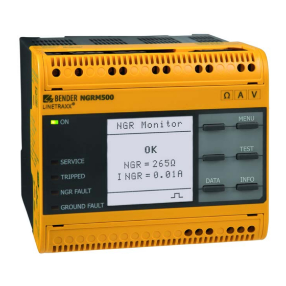
Mounting 4.2 Enclosure view NGRM500 Ground fault NGR fault Trip 11 12 14 21 22 24 31 32 34 NGRM500 Ω A V ® LINETRAXX MENU NGR Monitor Front RESET TEST NGR = 265Ω SERVICE I NGR = 0,01A TRIPPED... -
Page 19: Screw Mounting
Mounting 4.3 Screw mounting 1. Fix the three mounting clips delivered with the device (two of them packed separately) manually or using a tool, as illustrated below. 2. Drill the mounting holes for the M4 thread according to the drilling template. 3. -
Page 20: Din Rail Mounting
Mounting 4.4 DIN rail mounting 1. Fix the three mounting clips delivered with the device (two of them packed separately) manually or using a tool, as illustrated below. 2. Snap the NGRM5… on the DIN rail. 3. Fix the NGRM5… to the DIN rail by pushing the mounting clips until they click into place. -
Page 21: Connection
Connection 5. Connection 5.1 Connection requirements Only qualified personnel are permitted to carry out the work necessary to install, commission and run a device or system. Risk of electrocution due to electric shock! Touching live parts of the system carries the risk of: An electric shock ... -
Page 22: Connection Descriptions Of Cd-Series Coupling Device
Connection 5.2 Connection descriptions of CD-series coupling device Connection to star point G1, R Connection to R of the NGRM5… CD1000-2 CD1000 CD14400 G, E Connection to E of the NGRM5… CD5000 CD25000 Connection to the protective earth conductor of the installation (PE) 5.3 Recommended connecting cable coupling device CD…... -
Page 23: Star Connection
Connection 5.4 Star connection 5.4.1 Connection Circuit breaker Ground fault NGR fault Trip 11 12 14 21 22 24 31 32 34 AC/DC 48...240 V NGRM5… LINETRAXX® CD... (G1) E (G) Ethernet Fig. 5.1: Star configuration The "N" connection of the CD-series coupling device should be as close to the transformer star point as possible. -
Page 24: Connection With Pulser
Connection 5.4.2 Connection with pulser Circuit breaker Ground fault NGR fault Trip 11 12 14 21 22 24 31 32 34 AC/DC 48...240 V NGRM5… LINETRAXX® CD... (G1) E (G) Ethernet Pulser OUT Pulser Fig. 5.2: Connection with pulser The "N" connection of the CD-series coupling device should be as close to the transformer star point as possible. -
Page 25: Artificial Neutral (Delta Connection)
Connection 5.4.3 Artificial neutral (delta connection) If no star point is available, the following circuit can create an artificial neutral. Connection with a zigzag transformer Circuit breaker Ground fault NGR fault Trip 11 12 14 21 22 24 31 32 34 AC/DC 48...240 V NGRM5…... -
Page 26: Ct Connection
1…25 A 5…25 A 5…1000 A 0…3800 Hz 42…3800 Hz 50/60 Hz Measuring range (see Transformation CTUB103 manual) ratio Bender meas- 5 A 100:1 600:1 uring current trans- 10 A 200:1 former 25 A 500:1 max. 30 m max. 40 m max. -
Page 27: Connection Of Relays (Ground-Fault, Ngr-Fault And Trip Relay)
Connection 5.6 Connection of relays (ground-fault, NGR-fault and trip relay) Ground-fault relay NGR-fault relay Trip relay Fig. 5.4: Connection of relays 5.7 Connection to the X1 interface Digital 1 (configurable: pulser, NGR method) Reset IN Test IN Modbus RTU (A) Modbus RTU (B) Common Analogue output... -
Page 28: X1: Input I1
Connection 5.7.1 X1: Input I1…3 The input is only detected as "activated" after the contact has been activated for at least 150 ms. This way, short interference pulses are ignored. Active high Active low I1…3 I1…3 open open Switch Switch closed closed Digital 1,... -
Page 29: X1: Output Q1
Connection 5.7.2 X1: Output Q1…2 Internal 24 V Connection to PLC +24 V, +24 V, max. 100 mA max. 100 mA Pull up Pull up 10 kΩ 10 kΩ max. 300 mA, 24 V External supply e.g.12...24 V +24 V, max. -
Page 30: X1: Analogue Output
Connection 5.7.3 X1: Analogue output Analogue output Mode Permissible load Current output 0…20 mA ≤ 600 Ω 4…20 mA ≤ 600 Ω 0…400 μA ≤ 4 kΩ Voltage output 0… 10 V ≥ 1 kΩ 2… 10 V ≥ 1 kΩ Either NGR current I or NGR resistance R can be assigned to the analogue out-... -
Page 31: User Interface
User interface 6. User interface 6.1 Operating elements NGRM500 ® LINETRAXX MENU RESET TEST SERVICE < TRIPPED INFO DATA NGR FAULT GROUND FAULT Legend to operating elements Description Explanation Display elements Operation LED, green; on when power supply is available The LC display shows device and measurement information. - Page 32 User interface Description Explanation The LED flashes in case of a prewarning: ground fault detected, ground-fault relay has tripped, trip relay has not tripped yet (t GROUND elapses). trip FAULT The LED is on: ground fault detected, trip relay has tripped (if con- figured).
-
Page 33: Standard Display
User interface 6.2 Standard display NGRM500 Ω A V ® LINETRAXX MENU NGR Monitor RESET TEST NGR = 265Ω SERVICE I NGR = 0,01A TRIPPED INFO DATA NGR FAULT GROUND FAULT The pulse symbol in the lower part of the display indicates that the resistance of the R is actively measured. -
Page 34: Fault Indication (Inactive)
User interface 6.4 Fault indication (inactive) NGRM500 Ω A V ® LINETRAXX MENU UNGR(rms) Limit 269 V RESET TEST SERVICE 03.09.18 12:38 TRIPPED 03.09.18 12:38 DATA NGR FAULT GROUND FAULT An inactive fault is indicated on the display with a . -
Page 35: History Memory
If the maximum number of memory entries has been reached, the oldest entry will be overwritten by a new event record. Display the history memory at MENU > 3. History NGRM500 Ω A V ® LINETRAXX... -
Page 36: Menu
Menu 7. Menu 7.1 Overview 1. Data meas. values , Method, R NGR rel sense, rms rel rms rel, fund fund rel fund fund rel, harm harm rel harm harm rel, 2. Harmonics 3. History History, Delete 4. Pulser Pulser, t Impuls 5. -
Page 37: Navigating Through The Menu
Return from any (sub)menu to the standard display by pressing and holding ESC for more than 2 s. 7.3 Changing settings Enter settings with text/numbers directly. There is a corresponding representation in the menu items: NGRM500 Ω A V ® LINETRAXX NGRM SERVICE <... -
Page 38: Data Measured Values (Menu 1)
Menu 7.4 Data measured values (menu 1) List of measured values. Navigate through the list using the buttons. Parameter Explanation NGR resistance value NGR relative resistance value NGR rel Method Measurement method (see menu 6.3) Resistance value; CD-series coupling device Sense Current;... -
Page 39: Harmonics (Menu 2)
Menu 7.5 Harmonics (menu 2) The measured harmonics are represented in a bar graph as a percentage of the meas- ured value in relation to the nominal value. Change between the harmonic voltage and current displays using the buttons. Scroll through the harmonics up to the 64 order using the buttons. -
Page 40: Pulser (Menu 4)
Menu 7.7 Pulser (menu 4) A ground fault can be located by means of a measuring clamp-on ammeter and the pulser function. The pulser relay is designed as Open Collector. Pulser (menu 4.1) Active - The pulser is continuously active regardless of ground faults that have ... -
Page 41: Hrg/Lrg Settings (Menu 6)
Menu 7.9 HRG/LRG settings (menu 6) 7.9.1 HRG system (menu 6.1) Menu Parameter Setting range Explanatory notes 6.1.1 400 V…25 kV System phase-to-phase voltage sys (L-L) For CD1000 and CD1000-2, select "CD1000" in CD1000, CD5000, the menu. CD14400 6.1.2 CD-NGRM The selection depends on the system voltage CD25000 Other... -
Page 42: Ngr (Menu 6.3)
Menu 7.9.3 NGR (menu 6.3) Menu Parameter Setting range Explanatory notes auto: automatic changeover between active and passive resistor monitoring; setting for field calibration passive: only passive resistor monitoring (see Page 14) auto, passive, 6.3.1 Method external: If "Digital 1 > NGR method" external (menu 6.5.5.3) is set, switching takes place depending on the condition of the digital input... - Page 43 Menu a) Ground-fault trip "on" When a ground fault is detected the ground-fault relay (connections 11, 12, 14) switches immediately (40 ms). the trip relay (connections 31, 32, 34) switches after t has elapsed. GF trip b) Ground-fault trip "off"...
- Page 44 Menu Relay and restart response values Menu Menu Parameter Setting range Explanatory notes Value in % of the nominal value at 6.4.1 10…90 % NGR trip which the ground-fault relay trips. The trip relay only trips (with the con- 6.4.2 10…90 % NGR trip figured delay) when the ground fault...
- Page 45 Menu Menu Menu Parameter Setting range Explanatory notes Time delay between fault elimination restart and automatic restart of the installa- On the 6.4.9 6.4.8 100 ms…24 h tion; only used when "Alarm stored > device: off" has been selected. t(restart) Number of restart attempts within 6.4.10 6.4.9 Restart count 1…5...
-
Page 46: System Settings (Menu 6.5)
Menu 7.9.5 System settings (menu 6.5) Setting Menu Parameter Explanatory notes range Fail-safe, Mode (6.5.1.1) Ground- non-fail-safe 6.5.1 fault relay Relay test (6.5.1.2) on, off Fail-safe, Mode (6.5.2.1) NGR-fault non-fail-safe 6.5.2 relay Relay test (6.5.2.2) on, off Fail-safe, Mode (6.5.3.1) non-fail-safe 6.5.3 Trip relay... -
Page 47: Field Calibration (Menu 6.6)
Menu Legend, Table 7.6 Fail-safe: The relay is energized during normal operation and is de-energized in the event of a fault ("fail-safe") Non-fail-safe: The relay is de-energized in normal operation and is energized in the event of a fault ("non-fail-safe") When set to "on", the function of the relay is checked during a test by switching it. -
Page 48: Device Settings (Menu 7)
Menu 7.10 Device settings (menu 7) Further information on the configurable parameters can be found following the over- view in the table. Menu Parameter Note German English GB Language English US Spanish French Time (7.2.1) Set local time 12 h (am/pm) Format (7.2.2) 24 h Summer time (7.2.3) - Page 49 Factory settings factory settings Update via interface Software UPDATE Service For Bender service only Tab. 7.7: Device settings overview (menu 7) Explanatory notes Table 7.7 Summer time (menu 7.2.3) No automatic change between summer time and standard time. Daylight Saving Time Automatic change between summer time and standard time according to North American regulation.
- Page 50 Menu Central European Summer Time CEST Automatic change between summer time and standard time according to Central European regulation. Central European summer time begins on each last Sunday in March at 02:00 CEST by setting the clock forward by one hour from 02:00 to 03:00. Central European sum- mer time always ends on the last Sunday in October at 03:00 CEST by setting the clock back one hour from 03:00 to 02:00.
- Page 51 Menu IP (menu 7.3.2.2) Set the appropriate IP address for the NGRM5… SN (menu 7.3.2.3) Set the appropriate subnet mask. Std. GW (menu 7.3.2.4) If a standard gateway is used, enter the IP address here. DNS server (menu 7.3.2.5) If a DNS server is used, enter the server's IP address. For questions regarding the configuration of a DNS server, please contact your network administrator.
-
Page 52: Commissioning (Menu 8)
Menu Modbus RTU (menu 7.3.5) Settings for communication with other devices via Modbus RTU. Address (menu 7.3.5.1): 1…247 Baud rate (menu 7.3.5.2): the selectable options are 6 kbaud, 19.2 kbaud, 38.4 kbaud, 57.6 baud ... -
Page 53: Info (Menu 9)
Menu 7.12 Info (menu 9) The current settings of the NGRM5… can be viewed in the Info menu. Navigate through the different views using the arrow buttons: Device name, serial number, article number Measurement equipment software version, HMI software version Software Time, date, summer time Clock... -
Page 54: Initial Commissioning
Initial commissioning 8. Initial commissioning The following parameters must be entered for initial commissioning: System voltage U (phase-to-phase) The corresponding coupling device must be used depending on the system voltage: for U ≤ 4.3 kV: CD1000, CD1000-2, CD5000 (20 kΩ) for U >... -
Page 55: Output Relays Operating Modes
Initial commissioning Resistance trip threshold ( Both trip thresholds for the resistance are set as a percentage of the nominal NGR NGR nom Setting range of trip threshold R 10…90 % (factory setting 50 %) 110…200 % (factory setting 200 %). The upper trip threshold for the resistance is set in Ω. -
Page 56: Trip Times
Initial commissioning 8.2.2 Trip times The three relays have different trip times: Ground-fault relay 40 ms, not configurable NGR-fault relay 7.5 s, not configurable Trip relay 100 ms…48 h, configurable for ground faults; 0…48 h, configurable for NGR faults Explanatory notes on trip relay In case of a ground fault, t is only considered when "Ground-fault trip"... - Page 57 Initial commissioning Ground-fault relay timing diagram Ground fault Ground fault Ground-fault relay Trip relay 40 ms = 100 ms...48 h,∞ GF Trip Fig. 8.1: Ground-fault relay timing diagram NGR-fault relay timing diagram NGR fault NGR fault NGR-fault relay Trip relay <...
-
Page 58: Rms Trip Signal, Fundamental, Harmonics
Initial commissioning 8.3 RMS trip signal, fundamental, harmonics The measured value which causes tripping can be selected via the "Trip signal" parameter (menu 6.4). Trip signal can be: The RMS value of current or voltage over the entire frequency range (up to approx. 3.8 kHz). - Page 59 Initial commissioning Timing diagram device start Ground fault/ NGR fault Supply Power Trip relay energized de-energized fail-safe de-energized Trip relay de-energized energized non-fail-safe Initial GF Trip Boot Time Measurement Normal 9…11 s 4…6 s operation NGR Trip Fig. 8.3: Timing diagram device start NGRM5xx_D00373_06_M_XXEN/02.2022...
-
Page 60: Analogue And Digital I/O Configuration
Analogue and digital I/O configuration 9. Analogue and digital I/O configuration 9.1 Analogue output (menu 6.6.4) Either NGR current I or NGR resistance R (HRG devices only) can be assigned to the analogue output. A voltage or current signal proportional to the measured value is applied to the output. -
Page 61: Use Of Q1: Device Health
Analogue and digital I/O configuration 9.2.1 Use of Q1: Device health No device Intern. 24 V Device error Mode error +24 V, detected detected max. 100 mA Pull up Fail-safe energized de-energized 10 kΩ Q1 low Q1 high 24 V, max. -
Page 62: Test Cycle
Test cycle 10. Test cycle Since the relays are not monitored in the hardware or software, they must be tested at regular intervals to verify proper functioning. The frequency of the test cycle is subject to the safety requirements of the operator but it must be carried out at least every six months. -
Page 63: Factory Settings
Factory settings 11. Factory settings Menu Factory settings Menu 6.1: HRG/LRG system 1. U 400 V sys (L-L) 2. CD-NGRM CD1000 3. Frequency 50 Hz 4. I NGR nom 5. R 150 Ω NGR nom Menu 6.2: CT 1. CT primary 2. - Page 64 Factory settings Menu Factory settings 11. Trip signal 10. Trip signal 12. Upper limit 11. Upper limit harmonic harmonic 13. Lower limit 12. Lower limit harmonic harmonic Menu 6.5: System settings Mode fail-safe 1. Ground-fault relay Rel. test Mode fail-safe 2.
-
Page 65: Error Codes
The installation must operate error- free before starting a field calibration. Field calibration could not be 6.11 Restart field calibration. started If the error persists, contact the Bender service. Connection between measur- Check connection between measur- 7.61…7.63 ing equipment and display ing equipment and display unit. -
Page 66: Technical Data
Technical data 13. Technical data 13.1 Tabular data Insulation coordination according to IEC 60664-1/IEC 60664-3/DIN EN 50178 Definitions Supply circuit (IC1) ................................(A1, A2) Measuring circuit/Control circuit (IC2) ...................... (RS, E, CT), (X1, ETH) Output circuit 1 (IC3)..............................(11, 12, 14) Output circuit 2 (IC4).............................. - Page 67 Technical data Supply voltage Nominal supply voltage U ..........................AC/DC, 48…240 V for UL applications.........................AC/DC, 48…240 V for AS/NZS 2081 applications .......................AC/DC, 48…230 V Tolerance U ..................................±15 % Tolerance U (for UL applications)........................–50…+15 % Tolerance U (for AS/NZS 2081 applications).....................–25…+20 % Frequency range U .............................
- Page 68 Technical data Measuring circuit 50 mA Nominal measuring current I ................ DC / 50/60 Hz / 50…3200 Hz 50 mA Maximum continuous current ..........................2 x I Overload capacity ............................. 10 x I for 2 s Measurement accuracy ..........................±2 % of I Load..................................68 Ω...
- Page 69 Technical data Digital inputs Galvanic separation................................... no Length connecting cables ............................max. 10 m ....................................DC 0 V, 24 V Overload capacity................................–5…32 V Digital outputs Galvanic separation................................... no Length connecting cables ............................max. 10 m Currents (sink) for each output ..........................max. 300 mA Voltage ....................................24 V Overload capacity................................–5…32 V Analogue output (M+)
- Page 70 Technical data Classification of climatic conditions acc. to IEC 60721 (except condensation and formation of ice) Stationary use (IEC 60721-3-3) ........................... 3K23 Transport (IEC 60721-3-2).......................2K11 (–40…+85 °C) Long-term storage (IEC 60721-3-1) ..................1K22 (–40…+70 °C) Classification of mechanical conditions acc. to IEC 60721 / IEC 60255-21 / DIN EN 60068-2-6 Stationary use ................................
-
Page 71: Standards, Approvals, Certifications
The specified standards take into account the edition valid until 09.2021 unless other- wise indicated. UL File Number: E493737, E173157 13.3 Ordering details 13.3.1 NGR monitor Supply voltage/Frequency range Type Art. No. NGRM500 B94013500 AC 48…240 V, 40…70 Hz DC 48…240 V NGRM550 B94013550 13.3.2 Accessories Measuring current transformers... -
Page 72: Document Revision History
Technical data Connecting cables CTUB103 Length (m) Type Art. No. CTXS-100 B98110090 CTXS-250 B98110091 CTXS-500 B98110092 CTXS-1000 B98110093 CD-series coupling device Voltage Type Art. No. 400…690 V CD1000 B98039010 400…1000 V CD1000-2 B98039053 1000…4200 V CD5000 B98039011 4300…14550 V CD14400 B98039054 14551…25000 V CD25000... - Page 73 INDEX DST (Daylight Saving Time) 49 Acknowledging a fault message 34 Alarm 53 Analogue output 60 Error codes 65 Ethernet 50 BCOM 51 Factory settings 63 Fault indication 33 Field calibration 47 CEST (Central European Summer Time) 50 Connection - Measuring current transformer 26 - Relay 27 Glossary 12 - Usys >...
- Page 74 INDEX Menu 2 39 Star connection Menu 3 39 - Usys > 690 V 25 Menu 4 40 - Usys ≤ 690 V 23 Menu 5 40 Subsystem 51 Menu 6 41 Support 8 Menu 7 48 Menu 8 52 Menu 9 53 Technical data 66 Modbus TCP 51...
- Page 76 Bender GmbH & Co. KG Londorfer Straße 65 • 35305 Grünberg • Germany Tel.: +49 6401 807-0 • info@bender.de • www.bender.de Exton PA, USA 800.356.4266 / 610.383.9200 • info@bender.org www.bender.org Canada Missisauga ON, Canada 800.243.2438 / 905.602.9990 • info@bender-ca.com www.bender-ca.com Mexico, South America, Central America, Caribbean info@bender-latinamerica.com...
Need help?
Do you have a question about the NGRM500 and is the answer not in the manual?
Questions and answers